Objective and use case
What you’ll build: Learn to build and test a stable digital input using a pull-up resistor and a pushbutton with a simple wiring guide.
Why it matters / Use cases
- Creating a reliable digital input for microcontroller projects, ensuring stable readings when the button is pressed.
- Utilizing pull-up resistors in IoT applications to maintain signal integrity in remote sensor deployments.
- Testing button functionality in prototypes to validate user interface designs before finalizing hardware.
- Implementing fail-safe mechanisms in safety-critical systems by ensuring default high state when the button is not pressed.
Expected outcome
- Stable voltage readings at V_IN with less than 0.1 V fluctuation when the button is not pressed.
- Response time of less than 10 ms when the button is pressed and released.
- Ability to measure voltages between 0 V and +5 V accurately using a multimeter.
- Consistent digital input signal with no false triggers during testing sessions.
Audience: Beginners in electronics; Level: Basic
Architecture/flow: Power supply connected to breadboard, resistor and button wired to create a stable digital input for measurement.
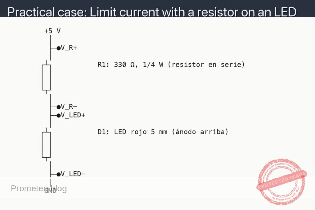
Materials
- 1 × Resistor 10 kΩ, 1/4 W (R1, pull-up)
- 1 × Momentary pushbutton, normally open (S1)
- 1 × 5 V DC supply (e.g., USB 5 V or bench supply)
- 1 × Breadboard
- 6 × Jumper wires
- 1 × Multimeter (DC volts mode)
- Optional: 1 × Microcontroller board (to read the input)
Wiring guide
- Abbreviations used in the schematic:
- V_IN: voltage at the node where R1, S1, and the MCU input meet. Measure here with the red probe.
- COM: common reference for measurements at ground. Connect the black probe here.
- Connect the power supply +5 V to the breadboard’s positive rail and its ground to the ground rail.
- Place R1 so that one end goes to +5 V and the other end creates a node on an empty row (this node will be V_IN).
- Place S1 so that one side connects to the V_IN node and the other side to the ground rail (GND).
- If using a microcontroller, connect the input pin to the V_IN node and the MCU ground to the same ground rail.
- For measurements, connect the multimeter black lead to the COM dot (ground) and touch the red lead to the V_IN dot.
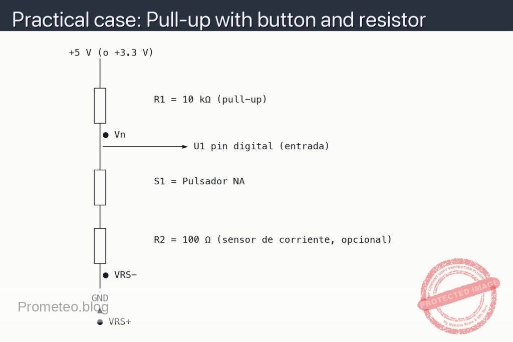
Schematic
          +5 V (o +3.3 V)
               │
               │
              ┌┴┐
              │ │        R1 = 10 kΩ (pull-up)
              │ │
              └┬┘
               │● Vn
               │──────────────► U1 pin digital (entrada)
               │
              ┌┴┐
              │ │        S1 = Pulsador NA
              │ │
              └┬┘
               │
              ┌┴┐
              │ │        R2 = 100 Ω (sensor de corriente, opcional)
              │ │
              └┬┘
               │● VRS−
               │
              GND
               ▲
               ● VRS+
Measurements and tests
-
Before powering:
- Verify R1 is between +V and the V_IN node, not to GND.
- Verify S1 is between the V_IN node and GND, not to +V.
- Confirm the supply polarity (+V to positive rail, GND to ground rail).
-
Voltage at V_IN (idle, button released):
- Set the multimeter to DC volts.
- Black probe to ●COM (GND), red probe to ●V_IN.
- With S1 not pressed, V_IN should read close to +5 V (within a few tens of millivolts of the supply).
-
Voltage at V_IN (button pressed):
- Keep probes as above.
- Press and hold S1. V_IN should drop to about 0 V.
- Release S1; V_IN should return to +5 V immediately.
-
Current check (sanity estimate):
- When S1 is pressed, current through R1 ≈ 5 V / 10 kΩ = 0.5 mA (well within safe limits for a 1/4 W resistor).
-
If using a microcontroller:
- Configure the input pin without internal pull-up/pull-down first.
- Read the pin: HIGH when S1 released, LOW when S1 pressed.
- Enable the MCU’s internal pull-up and repeat tests (you may remove R1 to compare behavior).
Common mistakes
- Using too small a resistor (e.g., 220 Ω), which wastes current and may stress components when the button is pressed.
- Wiring the button across +V and GND directly; this shorts the supply when pressed.
- Forgetting the ground reference for the multimeter, leading to erratic readings.
- Not sharing grounds between the microcontroller and the external circuit.
Safety notes
- This is a low-voltage circuit, but avoid shorting +5 V to GND.
- If using a bench supply, set current limit to around 100–200 mA.
Improvements and variations
- Debounce: add a small capacitor (e.g., 100 nF) from V_IN to GND to reduce contact bounce, or implement software debouncing.
- Pull-down variant: swap positions so R1 goes from V_IN to GND and the button connects V_IN to +V, inverting logic.
- EMI robustness: add a series resistor (e.g., 100 Ω) between the node and the MCU input to limit spikes.
More Practical Cases on Prometeo.blog
Find this product and/or books on this topic on Amazon
As an Amazon Associate, I earn from qualifying purchases. If you buy through this link, you help keep this project running.
Quick Quiz

Telecommunications Electronics Engineer and Computer Engineer (official degrees in Spain).