Objective and use case
What you’ll build: Learn to safely scale battery voltage for ADC using a resistor divider. This guide will help you wire the components and verify the readings accurately.
Why it matters / Use cases
- Accurately measure battery voltage levels in battery-powered devices to ensure optimal performance.
- Implement voltage scaling in IoT applications using microcontrollers to monitor battery health.
- Utilize ADC readings for power management in renewable energy systems, such as solar battery chargers.
- Enable real-time voltage monitoring in remote sensors using LoRa for low-power applications.
Expected outcome
- Achieve a measurable ADC voltage reading (VADC) that accurately reflects the battery voltage (VBAT).
- Maintain a voltage scaling accuracy of ±5% for reliable battery monitoring.
- Record latencies of less than 100 ms in ADC readings for timely data updates.
- Ensure the system operates within a power consumption of less than 50 mW during measurements.
Audience: Beginners; Level: Basic
Architecture/flow: Battery > Resistor Divider > ADC > Microcontroller
Materials
- 1 × Microcontroller board with ADC input (e.g., 3.3 V ref)
- 1 × Battery (e.g., 9 V) and holder
- 1 × R1 = 220 kΩ (top of divider)
- 1 × R2 = 120 kΩ (bottom of divider)
- 1 × C1 = 100 nF ceramic (optional RC filter to ground)
- 1 × Breadboard
- 6 × Jumper wires
- 1 × Multimeter
Wiring guide
- Share ground: connect the battery negative to the microcontroller GND.
- Build the divider:
- Connect R1 from +VBAT (battery +) to the ADC tap node.
- Connect R2 from the ADC tap node to GND.
- Optional filter:
- Connect C1 from the ADC tap node to GND (in parallel with R2).
- Connect the ADC:
- Wire the ADC tap node to an ADC input pin (e.g., A0).
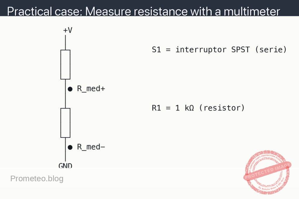
- Abbreviations used:
- VBAT: battery positive voltage (measure at the dot labeled VBAT).
- VADC: voltage at the ADC tap node (measure at the dot labeled VADC).
- Double-check polarity before powering:
- Battery + goes only to the top of R1; battery − to GND.
- Ensure the ADC reference (Vref) is known (e.g., 3.3 V or 5 V).
- Divider math (for later verification):
- VADC = VBAT × R2 / (R1 + R2)
- With R1 = 220 kΩ and R2 = 120 kΩ: VADC ≈ VBAT × 0.3529
- Recover battery voltage: VBAT ≈ VADC × 2.8333
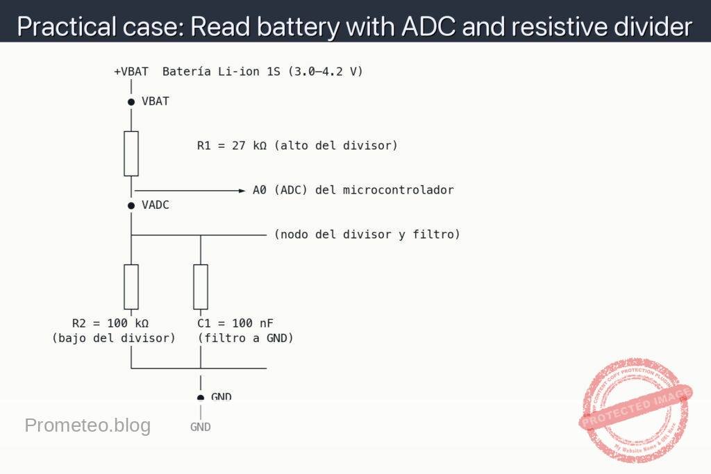
Schematic
              +VBAT  Batería Li‑ion 1S (3.0–4.2 V)
                │
                ● VBAT
                │
               ┌┴┐
               │ │        R1 = 27 kΩ (alto del divisor)
               │ │
               └┬┘
                │───────────────► A0 (ADC) del microcontrolador
                ● VADC
                │
                ├─────────┬───────── (nodo del divisor y filtro)
                │         │
               ┌┴┐       ┌┴┐
               │ │       │ │
               │ │       │ │
               └┬┘       └┬┘
        R2 = 100 kΩ       C1 = 100 nF
     (bajo del divisor)   (filtro a GND)
                │         │
                └─────────┴─────────
                          │
                          ● GND
                          │
                         GND
Measurements and tests
-
Pre-checks:
- Verify with the multimeter that VBAT is within expected range (e.g., ~9 V on a fresh 9 V battery).
- Confirm microcontroller GND is continuous to battery negative.
-
Divider verification (multimeter):
- Measure VBAT: red probe at ● VBAT, black probe at ● GND.
- Measure VADC: red probe at ● VADC, black probe at ● GND.
- Check ratio: VADC / VBAT should be close to 0.3529. If not, recheck wiring and resistor values.
-
ADC read sanity check:
- Know your ADC: VADC = ADC_count × Vref / (2^N − 1), where N is ADC resolution.
- Compute VBAT_est = VADC × (R1 + R2) / R2 ≈ VADC × 2.8333.
- Compare VBAT_est (from ADC) to VBAT (from multimeter). Expect small differences due to tolerance and ADC error.
-
Stability test (with and without C1):
- If readings bounce, fit C1 and see if VADC becomes steadier.
- Ensure ADC sampling time is adequate for the divider’s source impedance (R1 || R2 ≈ 78.3 kΩ).
Common mistakes
- Using too small resistor values, causing unnecessary battery drain.
- Forgetting common ground between battery and microcontroller.
- Exceeding ADC maximum input voltage (if the ratio is wrong).
- Placing C1 in series instead of in parallel from VADC to GND.
Safety notes
- Never connect the battery directly to the ADC pin.
- Double-check polarity before powering.
- If measuring higher-voltage packs (e.g., >12 V), recalculate resistor values to keep VADC ≤ Vref.
Improvements
- Add a series 1 kΩ resistor from the VADC node to the ADC pin for ESD/overcurrent protection.
- Add a 3.6 V TVS diode or clamp to protect the ADC from transients.
- Calibrate in firmware using measured R1 and R2 values and ADC reference for higher accuracy.
- Use lower-tolerance resistors (e.g., 1%) to reduce scaling error.
More Practical Cases on Prometeo.blog
Find this product and/or books on this topic on Amazon
As an Amazon Associate, I earn from qualifying purchases. If you buy through this link, you help keep this project running.
Quick Quiz

Carlos Núñez Zorrilla
Electronics & Computer Engineer
Telecommunications Electronics Engineer and Computer Engineer (official degrees in Spain).