Objective and use case
What you will build: A small RC circuit with a push button, capacitor, resistor, and buzzer that keeps the beep active for a short time after releasing the button. You will be able to adjust the duration of the beep by varying the values of R and C (≈0.3–2 s).
What it’s for
- Simulating a “confirmation beep” that lasts a bit longer than the quick tap of the button.
- Giving the user enough time to clearly perceive a short alert, for example in a homemade mini kitchen timer.
- Avoiding having to keep the button pressed in order to hear a clearly audible and stable tone.
- Practically demonstrating how a capacitor stores energy and releases it gradually through a resistor.
- Generating a short tail of sound when releasing a button in projects that will later be integrated with Arduino or other digital systems.
Expected result
- The buzzer sounds immediately while the button is pressed.
- When the button is released, the buzzer continues to sound for approximately 0.3 s to 2 s, depending on the chosen RC combination.
- The voltage at the capacitor node (“VA node”) drops from near +5 V to almost 0 V with an exponential curve typical of an RC circuit.
- Signal fall times are measured on the order of hundreds of milliseconds to a few seconds, in line with the time constant τ = R·C.
- The current flowing through the buzzer decreases smoothly, generating a tail of decreasing volume instead of an abrupt cut in the sound.
Target audience: People starting out in practical electronics and makers who have already assembled simple circuits with LEDs and resistors; Level: Beginner–intermediate.
Architecture/flow: Push button connects the supply (e.g., +5 V) to the VA node with the capacitor in parallel and the resistor in series to ground; the buzzer is powered from the VA node, so when pressed the capacitor charges and the buzzer sounds, and when released the capacitor discharges through the resistor and the buzzer, keeping the beep going while the voltage falls exponentially.
Materials
- 1 × 5 V DC power supply (can be a regulated USB port or a lab power supply).
- 1 × 5 V passive buzzer (two terminals, no internal oscillator; if you only have an active one it also works for the experiment).
- 1 × 470 µF electrolytic capacitor (anything between 220 µF and 1000 µF is also valid; voltage ≥ 10 V).
- 1 × 1 kΩ resistor (¼ W or similar).
- 1 × Normally open push button.
- 1 × Breadboard.
- 6–8 × Male-male jumper wires.
Wiring guide
Treat these connections as the official specification that the schematic must follow:
- Connect the positive terminal of the +5 V supply to a rail of the breadboard (call it “+5V”).
-
Connect the negative terminal of the supply to the GND rail of the breadboard (common ground, “GND”).
-
Connect one terminal of the push button to the +5V rail.
-
Connect the other terminal of the push button to a node that we’ll call “VA node”.
-
Connect the positive terminal of capacitor [C1] 470 µF between “VA node” and the breadboard GND:
- One terminal (marked “+”) of C1 to “VA node”.
-
The other terminal of C1 to GND.
-
Connect resistor [R1] 1 kΩ between “VA node” and the positive terminal of the buzzer:
- One end of R1 to “VA node”.
-
The other end of R1 to an intermediate node that we’ll call “VB node”.
-
Connect the positive terminal of the buzzer [BZ1] to “VB node”.
- Connect the negative terminal of the buzzer [BZ1] to the GND rail.
In summary, in chain form:
– +5V → Push button → VA node.
– VA node → (in parallel to GND) Capacitor C1.
– VA node → R1 → VB node → Buzzer → GND.
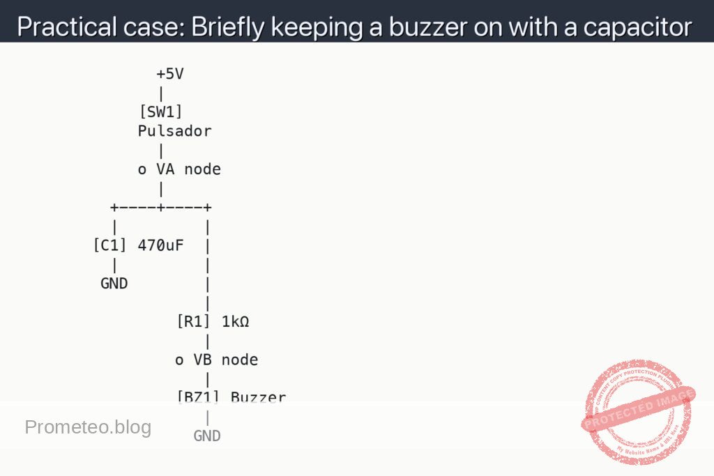
Schematic
               +5V
               |
             [SW1]
             Pulsador
               |
             o VA node
               |
          +----+----+
          |         |
        [C1] 470uF  |
          |         |
         GND        |
                    |
                 [R1] 1kΩ
                    |
                 o VB node
                    |
                 [BZ1] Buzzer
                    |
                   GND
Measurements and tests
-
Basic functional check:
- Press SW1 and keep it pressed: BZ1 should sound immediately.
- Release SW1: BZ1 should keep sounding for a short moment and its volume should gradually decrease until it turns off.
- Repeat short and long presses; observe how the duration of the beep after releasing seems similar in both cases (it depends more on the RC value than on press time, as long as the capacitor charges almost completely).
-
Measuring capacitor voltage (V_C1):
- V_C1 means the voltage between the positive terminal of C1 (at VA node) and GND.
- Place the positive probe of the multimeter at VA node and the negative probe at GND.
- With SW1 pressed, verify that V_C1 is close to +5 V (for example, between 4.8 V and 5.0 V if the supply is 5 V).
- Release SW1 and observe how V_C1 gradually decreases; note the time it takes to go down from 5 V to, for example, 2 V and then to 1 V.
-
Measuring voltage across the buzzer (V_BZ):
- V_BZ means the voltage between VB node (positive of the buzzer) and GND.
- Place the positive probe of the multimeter at VB node and the negative probe at GND.
- With SW1 pressed, V_BZ should be a few volts (it depends on the drop across the buzzer).
- When releasing SW1, observe that V_BZ falls along with V_C1; when V_BZ gets too low, the buzzer stops sounding.
-
Estimating the RC time constant:
- The time constant τ (tau) is τ = R × C.
- With R1 = 1 kΩ and C1 = 470 µF, τ ≈ 0.47 s.
- Observe experimentally whether the buzzer stops sounding in a time on the order of 1–2 seconds, which corresponds to several time constants (3–5 τ).
Simple explanation of how it works
- When you press the push button, the VA node is directly connected to +5 V.
- Capacitor C1 charges quickly to a voltage close to 5 V.
- While the capacitor is charged and the push button is still pressed, the buzzer receives voltage through R1 and sounds.
- When the push button is released, VA is no longer tied to +5 V, but C1 is still charged: now the capacitor discharges through R1 and the buzzer.
- This discharge is not immediate; it follows the RC circuit law, which is why the voltage falls exponentially and the buzzer keeps sounding a bit longer, with decreasing volume.
- The larger C1 or R1 is (the higher the R×C product), the longer it will take to discharge and the more the sound will be prolonged.
Possible tweaks and improvements
-
Increase beep time:
- Use a larger capacitor, for example 1000 µF, keeping R1 = 1 kΩ.
- Or increase R1 to 2.2 kΩ or 4.7 kΩ to lengthen τ.
- Keep in mind that too high an R can make the buzzer sound weaker.
-
Reduce beep time:
- Use a smaller capacitor (100 µF).
- Or reduce R1 to 470 Ω (if the buzzer and supply allow it) to increase the initial current and make the shutoff faster.
-
Using active vs passive buzzer:
- With an active buzzer (which has an internal oscillator), the behavior is usually more “all or nothing”: it will sound while the voltage is above a certain threshold and turn off abruptly.
- With a passive buzzer, the volume usually decreases more gradually.
-
Separate charge and discharge paths:
- A typical improvement is to use a diode so that the capacitor charges quickly and discharges more slowly (or vice versa), but that would already be a step toward a slightly more advanced use case.
Common mistakes and how to avoid them
-
Incorrect capacitor polarity:
- Electrolytic capacitors are polarized; the terminal marked with “-” or the dark stripe must go to GND.
- If you connect it backwards, it can be damaged, heat up, and even explode.
-
Confusing the buzzer terminals:
- Many buzzers have a “+” printed on the case: that goes on the VB node side.
- If you connect it backwards, it will normally not be damaged, but it might not sound right, especially if it is passive.
-
Miswired push button:
- Make sure the push button actually connects +5 V to VA node when you press it.
- On a breadboard, some push buttons have the pins internally connected in pairs; check the datasheet or test it with the multimeter in continuity mode.
-
Short circuits between +5 V and GND:
- Check that there is no wire directly joining the +5 V rail and the GND rail.
- If the power supply shuts down, heats up, or the USB disconnects, check the wiring immediately.
Basic safety
- Always work with low voltages (5 V in this case); it is much safer.
- Do not exceed the working voltage of the capacitor (use capacitors of at least 10 V for a 5 V supply).
- If a capacitor gets hot, smells strange, or you see it bulging, disconnect the power and do not keep using it.
- Do not intentionally short-circuit the output of the power supply.
With this small project you will clearly see how a capacitor can store energy and extend the operation of a load (the buzzer) for a short time, even after having “removed” the direct power with the push button.
More Practical Cases at Prometeo.blog
Find this product and/or books on this topic on Amazon
As an Amazon affiliate, I earn from qualifying purchases. If you buy through this link, you help keep this project going.
Quick quiz
More Practical Cases on Prometeo.blog

Telecommunications Electronics Engineer and Computer Engineer (official degrees in Spain).