Objective and Use Case
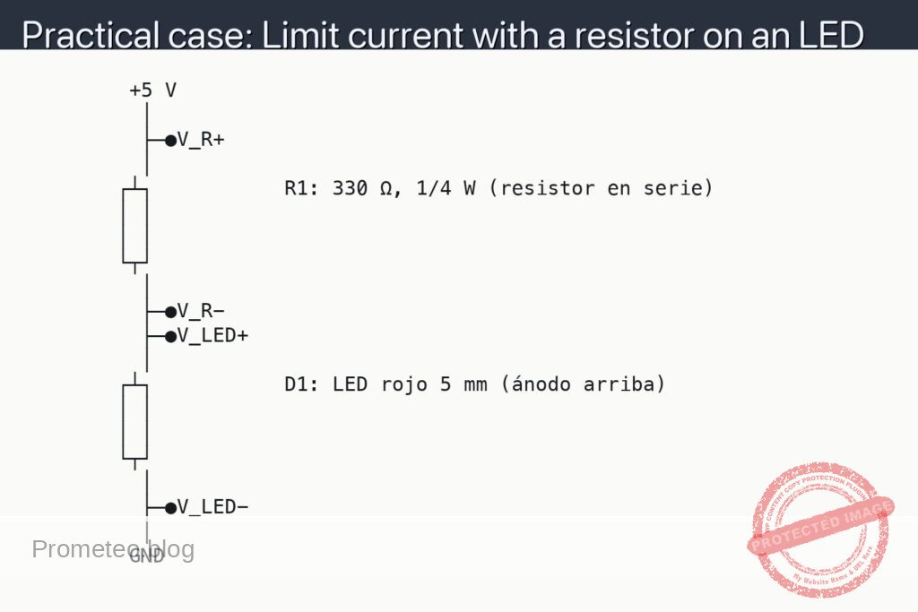
What you will build: An electromechanical doorbell with a coil that attracts a metal hammer to strike a small bell‑type plate, powered by a 9–12 V DC supply.
What it is used for
- Simulating how a classic home doorbell works in projects and school fairs.
- Demonstrating how an inductor converts electrical energy (9–12 V, 200–400 mA) into visible and audible mechanical motion.
- Implementing a low‑voltage alert in scale models (for example, when opening a door in a scale house).
- Showing the effect of self‑induction and the need for a protection diode in parallel with the coil.
- Practicing the safe control of inductive loads using a transistor as a power stage with a low‑current control signal.
Expected Result
- The coil is energized with ≈ 9–12 V DC and generates a magnetic field capable of attracting the hammer clearly and repeatedly.
- Current consumption of the coil between 200–400 mA, measured in series (I_COIL) without overheating the coil or the transistor.
- Collector‑emitter voltage of the transistor (V_CE) in the range of 0.2–0.4 V when the coil is activated, indicating proper saturation.
- Voltage on the coil (V_COIL) close to the supply voltage when the transistor is cut off and the doorbell is off.
- Audible strike of the plate when pressing the button, with no damage to components thanks to the protection diode and proper current sizing.
Target audience: High school students, beginner makers, and technology teachers; Level: Beginner–intermediate in basic electronics.
Architecture/flow: DC supply (9–12 V) → power transistor that switches the coil → coil that generates the magnetic field and moves the hammer → flyback diode to absorb voltage spikes from self‑induction → push button or logic signal that drives the transistor base → hammer strikes the plate, producing the doorbell sound.
Materials
- 1 × Regulated 9–12 V DC power supply (or good‑quality 9 V battery; preferably a pack of 8×AA 1.5 V).
- 1 × Doorbell coil or small electromagnet (typical DC resistance 20–60 Ω).
- 1 × General‑purpose NPN transistor (e.g., 2N2222 or BC337).
- 1 × Base resistor [R1] of 4.7 kΩ (for the transistor).
- 1 × Protection diode [D1] 1N4007 (or similar rectifier).
- 1 × Normally open push button.
- 1 × Metal plate or small bell (the doorbell “gong”).
- 1 × Metal piece or screw as a movable core / hammer (or flexible metal tongue).
- 1 × Protoboard (breadboard) or mounting base.
- Several × Breadboard wires (jumpers).
- 1 × Digital multimeter (to measure voltages and currents).
- 1 × Simple mechanical support (wood/cardboard) to fix the coil and bell (optional but recommended).
Wiring Guide
Treat this section as the official wiring specification. The schematic will follow these connections exactly.
- Power connections:
- Connect the positive terminal of the 9–12 V supply to the node labeled
+V. -
Connect the negative terminal of the supply to the node labeled
GND. -
Coil (inductor) connection:
- Connect one end of the doorbell coil to the
+Vnode. -
Connect the other end of the coil to node
VC(transistor collector). -
Protection diode across the coil:
- Connect the cathode of [D1] 1N4007 (end marked with a band) to node
+V. - Connect the anode of [D1] to node
VC. -
That is, the diode is in parallel with the coil but oriented opposite to the normal polarity of the supply.
-
NPN transistor (switching stage):
- Connect the collector of the NPN transistor to node
VC. - Connect the emitter of the NPN transistor to node
GND. -
Connect the base of the NPN transistor to node
VB. -
Base resistor and push button:
- Connect one end of resistor [R1] 4.7 kΩ to node
+V. - Connect the other end of [R1] to node
VBTN. - Connect one terminal of the push button to node
VBTN. - Connect the other terminal of the push button to node
VB. -
Optionally connect a 100 kΩ pull‑down resistor [R2] between node
VBandGND(if you have one; it helps keep the transistor fully off when not pressed).- One end of [R2] to node
VB. - The other end of [R2] to node
GND.
- One end of [R2] to node
-
Measurement node:
- Node
VCwill be the point where you measure collector voltage (V_CE) with respect toGND. - Node
VBwill be the point where you measure base voltage (V_B) with respect toGND. - You will measure coil current (I_COIL) by inserting the multimeter in series between
+Vand the coil during tests.
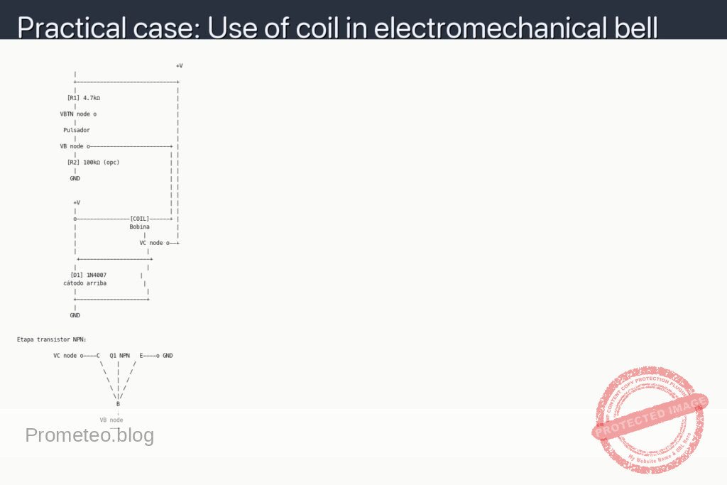
Schematic
                                                +V
                 |
                 +------------------------------+
                 |                              |
               [R1] 4.7kΩ                       |
                 |                              |
             VBTN node o                        |
                 |                              |
              Pulsador                          |
                 |                              |
             VB node o------------------------+ |
                 |                            | |
               [R2] 100kΩ (opc)               | |
                 |                            | |
                GND                           | |
                                              | |
                                              | |
                 +V                           | |
                 |                            | |
                 o----------------[COIL]------+ |
                 |                Bobina        |
                 |                    |         |
                 |                   VC node o--+
                 |                     |
                  +---------------------+
                 |                     |
                [D1] 1N4007          |
              cátodo arriba           |
                 |                     |
                 +---------------------+
                 |
                GND


Etapa transistor NPN:

           VC node o----C   Q1 NPN   E----o GND
                         \    |    /
                          \   |   /
                           \  |  /
                            \ | /
                             \|/
                              B
                              |
                         VB node
                            ---
Measurements and Tests
-
Basic verification without transistor (coil only):
- With the supply disconnected, measure the DC resistance of the coil with the multimeter in ohmmeter mode (typical value between 20–60 Ω).
- Calculate the expected current I_COIL = V / R_COIL (for example, for 12 V and 40 Ω → I_COIL ≈ 0.3 A) to confirm that your supply can provide it.
-
Supply voltage measurement:
- Set the multimeter to DC voltmeter mode.
- Measure the voltage between
+VandGNDto ensure that you actually have 9–12 V (red probe to +V, black probe to GND).
-
Measuring V_B (base voltage, VB):
- V_B means “voltage at the transistor base with respect to GND”.
- Place the black multimeter probe on
GNDand the red one on nodeVB. - With the button not pressed, V_B should be close to 0 V (especially if you use [R2] as a pull‑down resistor).
- With the button pressed, V_B should rise to about 0.7–1 V (typical of a conducting base‑emitter junction).
-
Measuring V_CE (collector‑emitter voltage):
- V_CE means “voltage between the collector and emitter of the transistor”.
- Place the black probe on
GND(emitter) and the red on nodeVC(collector). - With the button not pressed, V_CE ≈ supply voltage (+V), because the coil does not conduct and the transistor is cut off.
- With the button pressed, V_CE should drop to a low value (≈ 0.2–0.4 V) if the transistor saturates correctly, indicating that most of the voltage is now across the coil.
-
Measuring I_COIL (coil current):
- I_COIL means “current flowing through the coil”.
- Put the multimeter in DC ammeter mode (appropriate range, for example 1 A or 400 mA as expected).
- Disconnect the wire going from
+Vto the coil and instead connect the multimeter in series:- Red multimeter probe to node
+V. - Black multimeter probe to the end of the coil that previously went to
+V.
- Red multimeter probe to node
- Press the button briefly and read the current: it should be close to the calculated value (for example, 0.2–0.4 A). Do not hold it down for too long if the transistor gets hot.
-
Mechanical operation tests:
- Make sure the moving part (hammer or tongue) is well aligned: when the coil is energized, it should move toward the metal plate or bell.
- Press the button repeatedly: each time you should hear a click or a small “ding”.
- If there is no sound, try adjusting the distance between the coil core and the moving part (too far and it will not move; too close and it may stick).
Key Concepts About the Coil in This Doorbell
- Inductor as an electromagnet:
- The coil is an inductor: a set of wire turns that, when current flows, generates a magnetic field.
-
This magnetic field attracts ferromagnetic metal parts (iron, steel), which is what moves the doorbell hammer.
-
Self‑induction and protection diode:
- When you interrupt the coil current (by releasing the button), the magnetic field collapses.
- This rapid change in the field induces an opposite voltage (called “induced voltage” or “inductive spike”) that can be very high.
-
Diode [D1], placed in reverse parallel across the coil, provides a safe path for this induced current and limits the overvoltage, protecting the transistor.
-
Using the transistor as an electronic switch:
- The NPN transistor acts here as a switch controlled by base current.
- When the base receives current through [R1] (button pressed), the transistor conducts and allows current to flow through the coil.
- When the base is at 0 V (button released), the transistor switches off and the coil is de‑energized.
Common Mistakes and How to Avoid Them
- Forgetting the protection diode [D1]:
- Without [D1], the transistor can be damaged by coil voltage spikes.
-
Symptoms: transistor getting very hot or failing suddenly.
-
Reversed diode polarity:
- If you connect the diode the wrong way around (anode to +V, cathode to VC), the coil will not activate because the diode will cause a short circuit (with high current).
-
Remember: diode band (cathode) toward
+V, unmarked end (anode) towardVC. -
Transistor pins swapped:
- Different models (2N2222, BC337, etc.) have different pin layouts (E‑B‑C).
-
Always check the datasheet to know which pin is collector, base, and emitter.
-
AC doorbell coil used with DC without checking:
- Some commercial doorbells are designed for 230 V AC and not for low‑voltage DC.
- Always use a coil/electromagnet suitable for 9–12 V DC or a low‑voltage doorbell.
Possible Improvements and Extensions
- Automatic (repeating) doorbell:
- Add a mechanical contact that opens and closes due to the hammer’s own motion (classic doorbell style), so it makes a continuous “drrrrring” while you keep the button pressed.
-
This can be implemented with a flexible tongue that touches a contact when at rest and releases it when attracted by the coil.
-
Control from a microcontroller:
- Replace the push button with a digital output from an Arduino or similar.
-
Keep the same power stage with transistor and diode so as not to overload the microcontroller output.
-
Waveform measurement with an oscilloscope:
- If you have an oscilloscope, observe the voltage waveform at node
VCwhen you cut the current. -
You will see how the diode clips the inductive spike and limits the voltage.
-
Doorbell optimization:
- Try coils with different numbers of turns or different cores (iron screw, solid bolt, laminated core).
- Adjust the distance between the coil and the moving piece to maximize force and sound without it getting stuck.
With this practical project you will have seen, in a very tangible way, how an inductor works as an electromagnet, why it generates voltage spikes when disconnected, and how to protect the circuit with a diode, all applied to something very everyday: an electromechanical doorbell.
More Practical Cases on Prometeo.blog
Find this product and/or books on this topic on Amazon
As an Amazon affiliate, I earn from qualifying purchases. If you buy through this link, you help support this project.
Quick Quiz

Telecommunications Electronics Engineer and Computer Engineer (official degrees in Spain).