Objective and use case
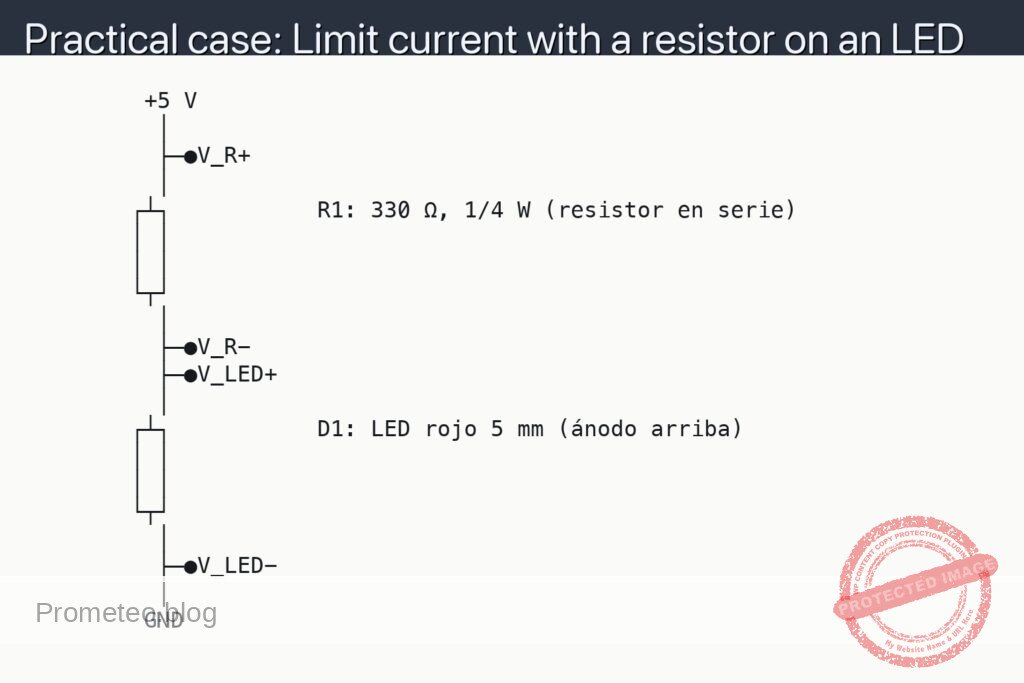
What you will build: A digital input for a microcontroller with a push button and a resistor in series (e.g. 10 kΩ) that limits the current and protects the GPIO pin when working with 5 V. You will also implement a small program that shows the button’s state changes on the serial monitor.
What it is used for
- Protect the GPIO pin when a push button is connected to 5 V on boards such as Arduino or ESP32.
- Avoid damage if the pin is accidentally configured as an output in the opposite state to the button level.
- Reduce current spikes caused by mechanical bouncing of the push button.
- Allow safe connection of external buttons on a breadboard or simple control panels.
- Illustrate the practical use of a series resistor with logic inputs as a basic design pattern.
Expected result
- The GPIO reads a stable level: ≈0 V (LOW) with the button released and ≈5 V (HIGH) when pressed.
- Current limited to a few hundred microamperes when pressed (I ≈ 5 V / 10 kΩ ≈ 0.5 mA).
- The voltage at the pin never exceeds the supply range of the microcontroller in normal use.
- A basic program reports each state change on the serial monitor without causing resets or lockups.
- No noticeable overheating of the microcontroller or resistor after several minutes of testing.
Target audience: People starting to work with microcontrollers and basic digital electronics; Level: beginner–intermediate.
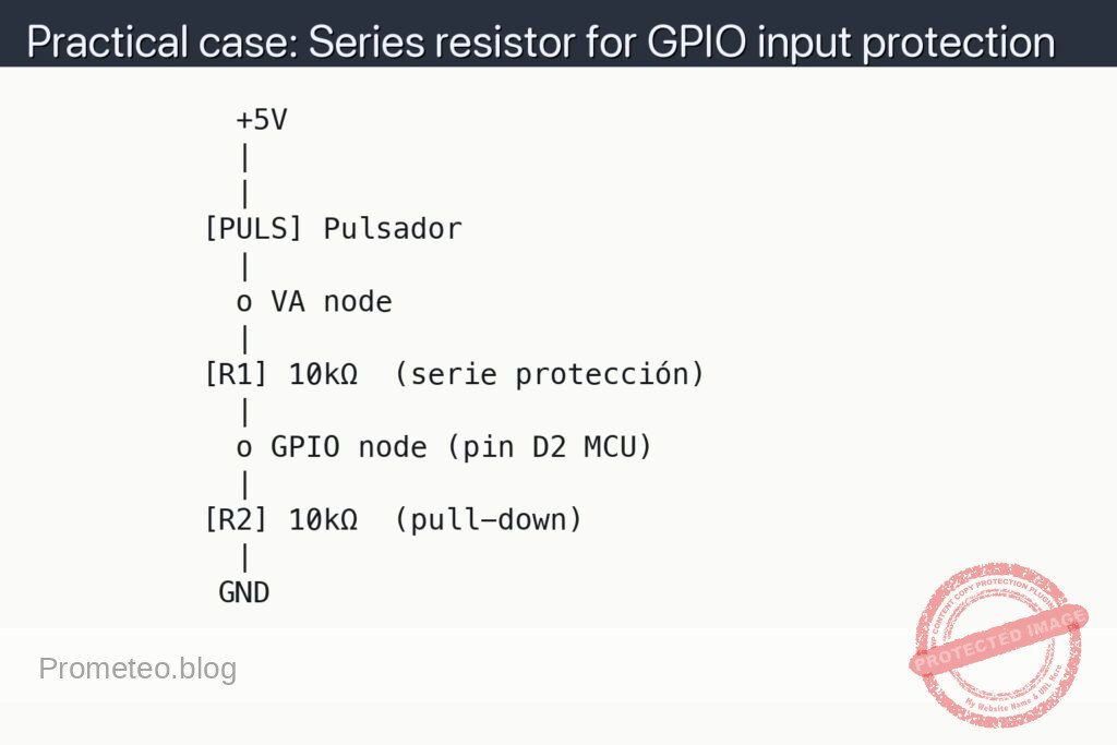
Architecture/flow: Push button connected to 5 V → series resistor (≈10 kΩ) → GPIO pin configured as input (ideally with an internal pull-down or complementary pull-up resistor) → firmware that reads the pin in a loop, detects edges, and sends events to the serial monitor.
Materials
- 1 × Development board with microcontroller (for example, Arduino Uno).
- 1 × Push button (4-pin or 2-pin type).
- 1 × 10 kΩ resistor (R1) in series with the GPIO input.
- 1 × 10 kΩ resistor (R2) for pull-down (reference to GND).
- 1 × 5 V supply (can be the same from the Arduino, +5V pin).
- 1 × Breadboard.
- 6–8 × Male-to-male jumper wires.
Wiring guide
- Connect the +5V pin of the microcontroller (for example, Arduino Uno) to the positive power rail of the breadboard (label it as +5V).
- Connect the GND pin of the microcontroller to the ground rail of the breadboard (label it as GND).
- Choose a digital pin on the microcontroller, for example GPIO D2; this will be the GPIO node.
- Connect one side of the push button to +5V.
- Connect the other side of the push button to the VA node (this will be the intermediate node between the push button and the series resistor).
- Connect resistor R1 = 10 kΩ between the VA node and the GPIO node (input protection series resistor).
- Connect resistor R2 = 10 kΩ between the GPIO node and GND (pull-down so that the pin is at 0 V when the button is not pressed).
- Verify that there is no direct connection (just a wire) between +5V and GND.
- In the microcontroller code, configure pin D2 as a standard digital input (INPUT, without internal pull-up).
Schematic
            +5V
            |
            |
          [PULS] Pulsador
            |
            o VA node
            |
          [R1] 10kΩ  (serie protección)
            |
            o GPIO node (pin D2 MCU)
            |
          [R2] 10kΩ  (pull-down)
            |
           GND
Measurements and tests
-
Basic check with multimeter:
- Measure continuity of the circuit with the multimeter in continuity mode between +5V and GND: it should not beep (there must be no direct short-circuit).
- Check the approximate value of R1 and R2 by measuring their resistance in ohms before assembling them (around 10 kΩ each).
-
Voltage measurement at the GPIO pin (V_GPIO):
- V_GPIO means “voltage at the GPIO pin” relative to GND.
- Place the black probe of the multimeter on GND and the red probe on the GPIO node.
- With the button RELEASED: you should measure approximately 0 V (thanks to resistor R2 as pull-down).
- With the button PRESSED: you should measure approximately 5 V (the voltage is transferred through R1 to the GPIO pin).
-
Current measurement through the series resistor (I_R1):
- I_R1 means “current flowing through resistor R1”.
- To measure current, the multimeter must be placed in series with the component:
- Disconnect the end of R1 that goes to the VA node.
- Connect the red probe of the multimeter to the VA node and the black probe to the free end of R1 (so the current passes through the multimeter).
- Press the button and read the current: you should get a value on the order of 0.5 mA (5 V / 10 kΩ = about 0.5 mA).
-
Functional test with the microcontroller:
- Upload a simple program that reads pin D2 and sends via the serial port the text “BOTON: PULSADO” or “BOTON: SUELTO”.
- Observe on the serial monitor that:
- Without pressing the button: a low state (logical 0) is reported stably.
- Pressing the button: a high state (logical 1) is clearly reported.
- If the microcontroller resets or hangs when pressing the button, check the connections and the values of R1 and R2.
-
Success criteria:
- V_GPIO ≈ 0 V with the button released and V_GPIO ≈ 5 V when pressed.
- I_R1 ≈ 0.5 mA (less than 1 mA) when the button is pressed.
- The microcontroller correctly detects the state changes without erratic behavior.
- There is no noticeable heating of the resistors or the microcontroller to the touch.
Common mistakes
- Connecting the push button directly between +5V and the GPIO pin without a series resistor:
- This often works, but reduces protection of the pin: if it is accidentally configured as a low output, the current can be very high (limited only by internal resistance).
- Forgetting the pull-down resistor (R2):
- The pin is left “floating” when the button is not pressed, causing random readings (spurious jumps between HIGH and LOW).
- Miswiring the 4-pin button:
- In many buttons the pins are paired internally; if it is wired in parallel instead of in series, the button may remain always active.
- Placing resistor R1 in the wrong place:
- R1 must go between the push button and the GPIO pin (VA node to GPIO node), not between +5V and the button, nor between GPIO and GND (that is the function of R2).
Safety and good practices
- Always work with a supply of 5 V or less for these basic exercises.
- Do not change the wiring with the circuit powered: first unplug the USB or the external power supply.
- Use resistor values of at least 1 kΩ when putting something in series with a GPIO pin, unless you have a clear reason to use less.
- Read in your microcontroller’s datasheet the maximum recommended current per pin and per port to know how much protection you need.
Possible improvements
- Add a small capacitor (for example, 100 nF) between the GPIO node and GND to further reduce button bounce (simple RC filter).
- Implement in the firmware a software debounce algorithm (for example, ignore changes within a 20 ms window).
- Replace R2 with a pull-up (between GPIO and +5V) and connect the other side of the push button to GND, with the same idea of adding R1 in series for protection.
- Try different values of R1 (4.7 kΩ, 22 kΩ, 47 kΩ) and observe how the current I_R1 and the noise picked up on the GPIO pin change.
More Practical Cases on Prometeo.blog
Find this product and/or books on this topic on Amazon
As an Amazon affiliate, I earn from qualifying purchases. If you buy through this link, you help to support this project.
Quick quiz

Telecommunications Electronics Engineer and Computer Engineer (official degrees in Spain).