Objective and use case
What you’ll build: a simple RC low-pass filter for a 5 V signal that reduces noise and smooths pulses generated by a push button, visible on an LED or oscilloscope.
What it’s for
- Smoothing a digital signal coming from a push button to avoid bouncing on a microcontroller input.
- Reducing fast noise on a 5 V supply line of a simple module, for example a sensor.
- Limiting brief voltage spikes when manually connecting or disconnecting a small load.
- Creating a somewhat more stable voltage reference from a 5 V source with high-frequency noise.
Expected result
- On the oscilloscope: input signal with sharp edges and small oscillations, and filtered signal with smooth rising and falling ramps.
- Clear difference between the node without filter and the filtered node when faced with fast pulses from the push button.
- At the filter output: reduction of fast variations by more than 50% in amplitude compared to the input (depending on the initial noise level).
- On the LED: less visible flicker and cleaner on/off transitions when repeatedly pressing the push button.
Target audience: people starting to work with analog electronics and microcontrollers; Level: beginner–intermediate.
Architecture/flow: push button or noisy 5 V source → series resistor → measured output node (LED and/or oscilloscope channel) → capacitor from the output node to ground forming the RC low-pass filter.
Materials
- 1 × 5 V DC power supply (can be a lab bench supply or USB + adapter).
- 1 × Normally open push button.
- 1 × Resistor R1 = 10 kΩ (to create the filter with the capacitor).
- 1 × Resistor R2 = 330 Ω (current limiter for the LED).
- 1 × Capacitor C1 = 10 µF (electrolytic or ceramic, voltage ≥ 10 V).
- 1 × Standard LED (red, green or similar).
- 1 × Breadboard.
- 6–10 × Male-male jumper wires.
- 1 × Digital multimeter (to measure voltages).
- (Optional but highly recommended) 1 × Oscilloscope (to see the input and output waveforms of the filter).
Wiring guide
- Connect the positive terminal of the 5 V supply to the node labeled +5V on the breadboard.
-
Connect the negative terminal of the supply to the common ground node labeled GND.
-
Push button connections (“noisy” signal source):
- Connect one terminal of the push button directly to +5V.
- Connect the other terminal of the push button to the node labeled VA node (this will be the noisy input signal).
-
Connect a pull-down resistor (R3 = 10 kΩ, implicitly internal in this scenario) between VA node and GND if your push button does not clearly pull the input to 0 V when released; if you don’t have R3, you can assume that VA node is left floating and you’ll see even more noise.
(To keep the circuit simple in the schematic, we’ll consider that pull-down resistor integrated; the RC filter will focus on R1 and C1.) -
RC low-pass filter connections:
- Connect resistor R1 = 10 kΩ between VA node and the node labeled VB node (filtered output).
-
Connect capacitor C1 = 10 µF between VB node and GND (respecting polarity if it is electrolytic: positive to VB node, negative to GND).
-
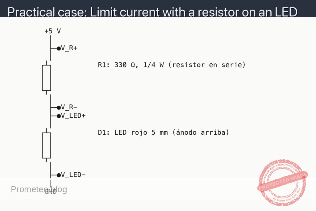
Filtered-signal LED indicator connections:
- Connect the LED anode (long lead) to node VB node.
- Connect the LED cathode (short lead) to resistor R2 = 330 Ω.
-
Connect the other end of R2 to GND.
-
Measurement points:
- Input measurement point: VA node (before the filter).
- Output measurement point: VB node (after the filter).
- Common measurement reference: GND.
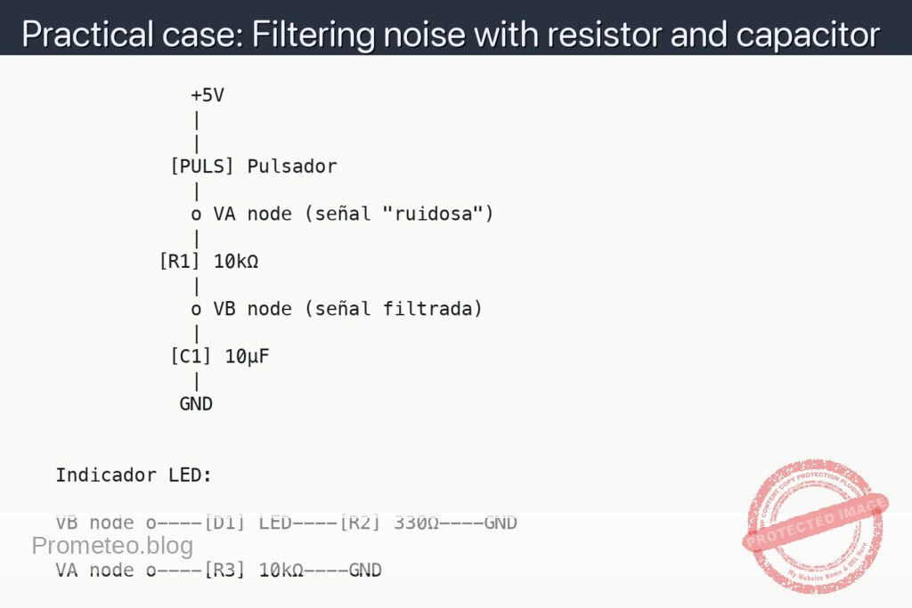
Schematic
               +5V
               |
               |
             [PULS] Pulsador
               |
               o VA node (señal "ruidosa")
               |
            [R1] 10kΩ
               |
               o VB node (señal filtrada)
               |
             [C1] 10µF
               |
              GND


   Indicador LED:

   VB node o----[D1] LED----[R2] 330Ω----GND

   VA node o----[R3] 10kΩ----GND
Measurements and tests
-
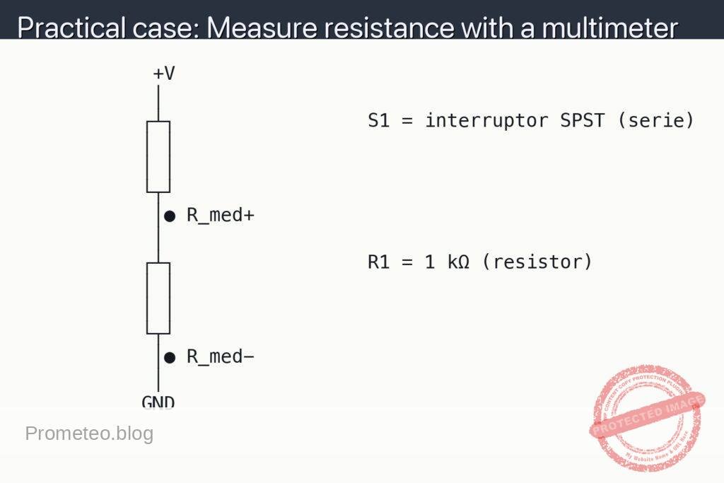
Basic measurements with a multimeter:
- Measure the voltage between VA node and GND (set the multimeter to DC voltmeter).
- Measure the voltage between VB node and GND.
- Press and release the push button: observe how at VA node the voltage rises and falls almost instantly toward 0 V and 5 V, while at VB node the rise and fall are slower (due to the RC effect).
-
Measurements with an oscilloscope (if you have one):
- Connect the probe of channel 1 of the oscilloscope to VA node and the ground clip to GND.
- Connect the probe of channel 2 of the oscilloscope to VB node and that channel’s ground clip also to GND.
- Adjust the time base to see transitions when you press the button (for example, 5 ms/div or 10 ms/div).
- Observe the waveform:
- At VA node you will see almost vertical edges and sometimes small bounces (short spikes) when pressing.
- At VB node those bounces will be much smaller or may even disappear; the transitions will be smooth curves (charging and discharging of the capacitor).
-
What each quantity you can measure means:
- V_VA: voltage at node VA with respect to GND. This is the “unfiltered” signal. Measure this voltage by placing the multimeter probe (or oscilloscope probe) on VA node and the reference on GND.
- V_VB: voltage at node VB with respect to GND. This is the signal filtered by the RC. Measure it the same way: probe on VB node and reference on GND.
- ΔV_ruido_entrada: maximum difference between the average value of the signal and the small fast spikes that appear on VA. You will clearly see it on the oscilloscope as “teeth” or “spikes” when pressing.
- ΔV_ruido_salida: the same difference but now on VB. If the filter works, ΔV_ruido_salida will be clearly smaller than ΔV_ruido_entrada.
-
Success criteria:
- The LED turns on when you press the button and turns off when you release it, with a somewhat smoother (not “instantaneous”) transition than if it were connected directly to VA.
- On the oscilloscope, the amplitude of the fast spikes (noise) on VB is much smaller than on VA.
- Capacitor C1 does not heat up and the circuit does not show short circuits (the supply does not go into protection nor drop sharply in voltage).
Common mistakes and how to avoid them
- Electrolytic capacitor polarity:
- Mistake: connecting the negative of C1 to node VB and the positive to GND.
- Consequence: the capacitor may be damaged, heat up or even explode.
-
Solution: make sure the terminal marked “–” goes to GND and the “+” terminal to VB node.
-
Missing LED current-limiting resistor:
- Mistake: connecting the LED directly between VB node and GND, without R2.
- Consequence: the LED may burn out due to excessive current; you may also overload the supply.
-
Solution: always keep resistor R2 = 330 Ω in series with the LED.
-
Short circuit between +5 V and GND:
- Mistake: accidentally connecting the power rails with a direct wire.
- Consequence: sudden drop of the supply voltage, possible damage to the supply or hot wires.
-
Solution: check that there is no wire directly connecting +5V to GND without components in between.
-
Confusing VA and VB nodes:
- Mistake: connecting R1 and C1 at the same node or swapping them such that an RC filter is not really formed in series with the signal.
- Consequence: no filtering occurs; the input and output signals are practically the same.
- Solution: verify that R1 is in series between VA node and VB node, and that C1 is between VB node and GND.
Suggested improvements and variations
- Change the value of R1:
- Try 1 kΩ, 4.7 kΩ, 47 kΩ.
-
Observe how the response speed changes: the smaller R1 is, the faster VB responds (less filtering); the larger R1 is, the slower it responds (more filtering).
-
Change the value of C1:
- Try 1 µF, 4.7 µF, 100 µF.
-
You’ll see that with more capacitance the transition is slower and fast noise is suppressed better.
-
Use the filter with a microcontroller digital input:
-
Instead of the LED, connect VB to the digital input of an Arduino (or similar) and check that pressing the button reduces false triggers or unstable readings.
-
Reuse the idea on power rails:
- Connect R1 in series with the 5 V line that powers a small module and C1 between the module’s input and GND (VB would be the module’s “filtered supply”).
- You’ll see that small noise or spikes produced by other elements connected to the same supply are smoothed out.
With this simple practical case, you now have a basic tool, the RC low-pass filter, to reduce noise in low-frequency signals using only one resistor and one capacitor.
More Practical Cases at Prometeo.blog
Find this product and/or books on this topic on Amazon
As an Amazon affiliate, I earn from qualifying purchases. If you buy through this link, you help support this project.
Quick quiz
More Practical Cases on Prometeo.blog

Telecommunications Electronics Engineer and Computer Engineer (official degrees in Spain).