

Level: Basic – Implement a logic circuit that triggers an indicator when any door is left ajar.
Objective and use case
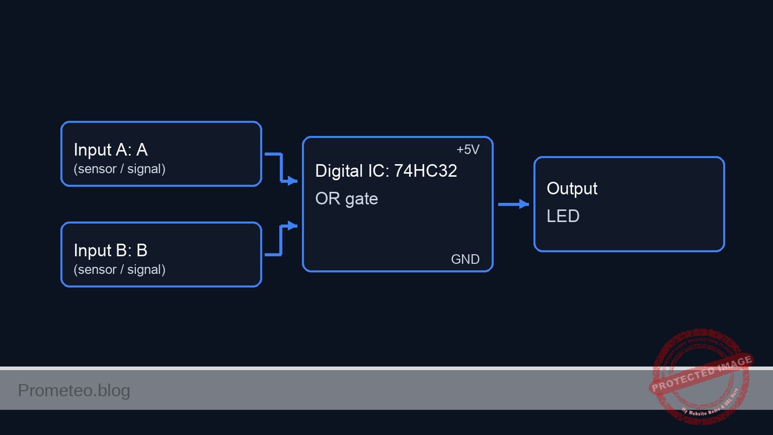
In this session, you will build a digital monitoring circuit using a 74HC32 OR gate to detect if any vehicle door is not fully closed. The circuit uses «Normally Closed» (NC) switches to simulate the door mechanics, ensuring that the alarm activates (LED turns ON) when a door opens.
-
Why it is useful:
- Automotive Safety: Alerts drivers if a door is not latched before driving, preventing accidents.
- Security Systems: Monitors multiple entry points (windows/doors) and triggers a central alarm if any single one is breached.
- Industrial Enclosures: Ensures safety guards on dangerous machinery are closed before operation is allowed.
- Access Control: Simple logic aggregation for multiple sensors.
-
Expected outcome:
- Both Doors Closed: Inputs are Logic 0 (0 V); LED is OFF.
- Door A Open: Input A becomes Logic 1 (5 V); LED turns ON.
- Door B Open: Input B becomes Logic 1 (5 V); LED turns ON.
- Both Open: Both inputs Logic 1; LED remains ON.
-
Target audience: Basic electronics students and automotive hobbyists.
Materials
- V1: 5 V DC power supply, function: main circuit power.
- S1: NC (Normally Closed) Pushbutton, function: Door A sensor (Released = Door Open).
- S2: NC (Normally Closed) Pushbutton, function: Door B sensor (Released = Door Open).
- R1: 10 kΩ resistor, function: pull-down for Input A.
- R2: 10 kΩ resistor, function: pull-down for Input B.
- U1: 74HC32, function: Quad 2-input OR gate IC.
- R3: 330 Ω resistor, function: LED current limiting.
- D1: Red LED, function: Open door warning indicator.
- C1: 100 nF capacitor, function: decoupling for U1 power supply.
Pin-out of the IC used
Selected Chip: 74HC32 (Quad 2-Input OR Gate)
| Pin | Name | Logic function | Connection in this case |
|---|---|---|---|
| 1 | 1A | Input A | Connected to Node DOOR_A |
| 2 | 1B | Input B | Connected to Node DOOR_B |
| 3 | 1Y | Output | Connected to Node V_ALARM |
| 7 | GND | Ground | Connected to Node 0 |
| 14 | VCC | Power | Connected to Node VCC |
Wiring guide
Follow these connections to create the SPICE-compatible netlist logic:
-
Power Supply
- V1 connects between node
VCCand node0(GND). - C1 connects between node
VCCand node0(near the IC).
- V1 connects between node
-
Input Stage (Door Sensors)
- S1 connects between node
VCCand nodeDOOR_A. - R1 connects between node
DOOR_Aand node0. (Ensures Logic 0 when door is closed/switch pressed). - S2 connects between node
VCCand nodeDOOR_B. - R2 connects between node
DOOR_Band node0.
- S1 connects between node
-
Logic Processing (74HC32)
- U1 Pin 14 connects to
VCC. - U1 Pin 7 connects to
0. - U1 Pin 1 (Input 1A) connects to node
DOOR_A. - U1 Pin 2 (Input 1B) connects to node
DOOR_B. - U1 Pin 3 (Output 1Y) connects to node
V_ALARM.
- U1 Pin 14 connects to
-
Output Stage (Indicator)
- R3 connects between node
V_ALARMand nodeLED_ANODE. - D1 anode connects to
LED_ANODE. - D1 cathode connects to node
0.
- R3 connects between node
Conceptual block diagram
Schematic
[ INPUT STAGE ]                      [ LOGIC STAGE ]                  [ OUTPUT STAGE ]

(VCC 5V)
   |
[ S1: Door A Switch (NC) ]
   |
   +---> [ Node: DOOR_A ] --(Pin 1)---->+------------------+
   |                                    |                  |
[ R1: 10k Pull-Down ] -> GND            |    U1: 74HC32    |
                                        |    (OR Gate)     |
                                        |                  |--(Pin 3)---> [ R3: 330 Ohm ]
                                        |    Logic:        |                   |
(VCC 5V)                                |    A + B = Y     |                   v
   |                                    |                  |             [ D1: Red LED ]
[ S2: Door B Switch (NC) ]              |                  |                   |
   |                                    |                  |                  GND
   +---> [ Node: DOOR_B ] --(Pin 2)---->+------------------+
   |                                            ^
[ R2: 10k Pull-Down ] -> GND                    |
                                          [ C1: 100nF ]
                                          (Decoupling)
Truth table
The 74HC32 behaves according to the standard OR logic. In this scenario:
* Logic 0 = 0 V (Door Closed / Switch Pressed).
* Logic 1 = 5 V (Door Open / Switch Released).
| Door A (Input 1) | Door B (Input 2) | Output (LED) | State Description |
|---|---|---|---|
| 0 (Closed) | 0 (Closed) | 0 (OFF) | Secure |
| 0 (Closed) | 1 (Open) | 1 (ON) | Warning |
| 1 (Open) | 0 (Closed) | 1 (ON) | Warning |
| 1 (Open) | 1 (Open) | 1 (ON) | Warning |
Measurements and tests
- Supply Verification: Measure the voltage between
VCCand0. It should be stable at 5 V. - Default State (Safe): Press and hold both S1 and S2 (simulating closed doors). Measure voltage at
DOOR_AandDOOR_B. Both should be ~0 V. The LED should be OFF. - Door A Test: Release S1 while holding S2. The voltage at
DOOR_Ashould jump to ~5 V. The voltage atV_ALARMshould go High (~5 V), and the LED should light up. - Door B Test: Release S2 while holding S1. The voltage at
DOOR_Bshould jump to ~5 V. The LED should light up. - Logic Threshold Verification: If using a variable supply, verify that the 74HC32 registers a «High» signal once the input voltage crosses approximately 3.5 V (for 5 V VCC).
SPICE netlist and simulation
Reference SPICE Netlist (ngspice) — excerptFull SPICE netlist (ngspice)
* Car Door Open Warning System
* Practical case implementation for ngspice

* --- Component Models ---
* Generic Red LED Model
.model DLED D(IS=10n N=2 RS=10 CJO=20p)
* Voltage Controlled Switch Model
* Vt=2.5V: Threshold voltage
* Ron=0.1: Resistance when ON (Closed)
* Roff=100Meg: Resistance when OFF (Open)
.model MYSW SW(Vt=2.5 Ron=0.1 Roff=100Meg)

* --- Power Supply ---
V1 VCC 0 DC 5

* --- Decoupling ---
C1 VCC 0 100n

* --- Input Stage: Door Sensors ---
* Logic:
* S1/S2 are NC (Normally Closed) Pushbuttons.
* Function: Released = Door Open. Pressed = Door Closed.
* Wiring: S1 connects VCC to DOOR_A. R1 pulls DOOR_A to GND.
* Simulation Logic:
* We use Voltage Controlled Switches (S1, S2) to simulate the physical contacts.
* Control Pulses (V_ACT_A, V_ACT_B) simulate the "Door Open" state.
* High Pulse = Door Open = Switch Released (Closed contacts) -> VCC connected.
* Low Pulse = Door Closed = Switch Pressed (Open contacts) -> Pulled to 0V.

* Door A
* ... (truncated in public view) ...
Copy this content into a .cir file and run with ngspice.
* Car Door Open Warning System
* Practical case implementation for ngspice

* --- Component Models ---
* Generic Red LED Model
.model DLED D(IS=10n N=2 RS=10 CJO=20p)
* Voltage Controlled Switch Model
* Vt=2.5V: Threshold voltage
* Ron=0.1: Resistance when ON (Closed)
* Roff=100Meg: Resistance when OFF (Open)
.model MYSW SW(Vt=2.5 Ron=0.1 Roff=100Meg)

* --- Power Supply ---
V1 VCC 0 DC 5

* --- Decoupling ---
C1 VCC 0 100n

* --- Input Stage: Door Sensors ---
* Logic:
* S1/S2 are NC (Normally Closed) Pushbuttons.
* Function: Released = Door Open. Pressed = Door Closed.
* Wiring: S1 connects VCC to DOOR_A. R1 pulls DOOR_A to GND.
* Simulation Logic:
* We use Voltage Controlled Switches (S1, S2) to simulate the physical contacts.
* Control Pulses (V_ACT_A, V_ACT_B) simulate the "Door Open" state.
* High Pulse = Door Open = Switch Released (Closed contacts) -> VCC connected.
* Low Pulse = Door Closed = Switch Pressed (Open contacts) -> Pulled to 0V.

* Door A
S1 VCC DOOR_A CTRL_A 0 MYSW
R1 DOOR_A 0 10k

* Door B
S2 VCC DOOR_B CTRL_B 0 MYSW
R2 DOOR_B 0 10k

* --- Control Signals (User Stimuli) ---
* Timing Sequence:
* 0us - 100us: Both Doors Closed (Low)
* 100us - 200us: Door A Open (High)
* 200us - 300us: Both Doors Open (High)
* 300us - 400us: Door B Open (High)
* 400us - 600us: Both Doors Closed (Low)
V_ACT_A CTRL_A 0 PULSE(0 5 100u 1u 1u 200u 1000u)
V_ACT_B CTRL_B 0 PULSE(0 5 200u 1u 1u 200u 1000u)

* --- Logic Processing: U1 (74HC32) ---
* Quad 2-input OR gate
* Connections per wiring guide:
* Pin 1 (A) -> DOOR_A
* Pin 2 (B) -> DOOR_B
* Pin 3 (Y) -> V_ALARM
* Pin 7 (GND) -> 0
* Pin 14 (VCC) -> VCC
XU1 DOOR_A DOOR_B V_ALARM 0 VCC 74HC32

* --- Output Stage: Indicator ---
R3 V_ALARM LED_ANODE 330
D1 LED_ANODE 0 DLED

* --- Subcircuits ---
.subckt 74HC32 InA InB OutY GND VCC
* Behavioral OR Gate implementation
* Uses tanh for continuous, robust switching
* Logic: Out = VCC if (A > 2.5) OR (B > 2.5)
* Formula: Vout = VCC * ( 1 - (NOT A * NOT B) )
* NOT A is approximated by 0.5 * (1 - tanh(10*(V(InA)-2.5)))
B1 OutY GND V = V(VCC) * (1 - ( (0.5*(1-tanh(10*(V(InA)-2.5)))) * (0.5*(1-tanh(10*(V(InB)-2.5)))) ))
.ends

* --- Analysis Directives ---
.tran 1u 600u
.print tran V(DOOR_A) V(DOOR_B) V(V_ALARM) V(LED_ANODE)
.op

.end
Simulation Results (Transient Analysis)

Show raw data table (1382 rows)
Index   time            v(door_a)       v(door_b)       v(v_alarm)
0	0.000000e+00	4.999500e-04	4.999500e-04	1.110223e-15
1	1.000000e-08	4.999500e-04	4.999500e-04	1.110223e-15
2	2.000000e-08	4.999500e-04	4.999500e-04	1.110223e-15
3	4.000000e-08	4.999500e-04	4.999500e-04	1.110223e-15
4	8.000000e-08	4.999500e-04	4.999500e-04	1.110223e-15
5	1.600000e-07	4.999500e-04	4.999500e-04	1.110223e-15
6	3.200000e-07	4.999500e-04	4.999500e-04	1.110223e-15
7	6.400000e-07	4.999500e-04	4.999500e-04	1.110223e-15
8	1.280000e-06	4.999500e-04	4.999500e-04	1.110223e-15
9	2.280000e-06	4.999500e-04	4.999500e-04	1.110223e-15
10	3.280000e-06	4.999500e-04	4.999500e-04	1.110223e-15
11	4.280000e-06	4.999500e-04	4.999500e-04	1.110223e-15
12	5.280000e-06	4.999500e-04	4.999500e-04	1.110223e-15
13	6.280000e-06	4.999500e-04	4.999500e-04	1.110223e-15
14	7.280000e-06	4.999500e-04	4.999500e-04	1.110223e-15
15	8.280000e-06	4.999500e-04	4.999500e-04	1.110223e-15
16	9.280000e-06	4.999500e-04	4.999500e-04	1.110223e-15
17	1.028000e-05	4.999500e-04	4.999500e-04	1.110223e-15
18	1.128000e-05	4.999500e-04	4.999500e-04	1.110223e-15
19	1.228000e-05	4.999500e-04	4.999500e-04	1.110223e-15
20	1.328000e-05	4.999500e-04	4.999500e-04	1.110223e-15
21	1.428000e-05	4.999500e-04	4.999500e-04	1.110223e-15
22	1.528000e-05	4.999500e-04	4.999500e-04	1.110223e-15
23	1.628000e-05	4.999500e-04	4.999500e-04	1.110223e-15
... (1358 more rows) ...
Common mistakes and how to avoid them
- Leaving Inputs Floating: Failing to install R1 or R2 will cause the inputs to «float» when the switch is open (pressed). This leads to erratic LED behavior. Always use pull-down resistors with this switch configuration.
- Confusing NC vs NO Switches: If you use NO (Normally Open) switches with this specific wiring, the logic reverses (LED ON when doors are closed). Ensure you understand the mechanical state of the switch when the door is physically closed.
- Missing LED Resistor: Connecting the LED directly to the IC output (Pin 3) without R3 will damage the LED or the 74HC32 chip due to excessive current.
Troubleshooting
- LED is always ON:
- Check if S1 or S2 are wired incorrectly (e.g., shorting VCC to Input constantly).
- Verify R1 and R2 are connected to Ground, not VCC.
- Ensure the IC is a 74HC32 (OR) and not a 74HC00 (NAND) or similar.
- LED never turns ON:
- Check power supply connections to Pin 14 and Pin 7.
- Ensure the LED polarity is correct (Anode to resistor, Cathode to GND).
- Verify the switches are actually passing 5 V when released.
- LED is dim:
- The value of R3 might be too high (e.g., 10 kΩ instead of 330 Ω).
- The power supply voltage might be below 3 V.
Possible improvements and extensions
- Audible Alarm: Connect a 5 V active buzzer in parallel with the LED (driven by a transistor if current exceeds 20 mA) to provide sound feedback.
- Interior Light Control: Add a delay circuit (using a capacitor and resistor or a 555 timer) so the light stays on for 10 seconds after the doors are closed, simulating a modern car courtesy light.
More Practical Cases on Prometeo.blog
Find this product and/or books on this topic on Amazon
As an Amazon Associate, I earn from qualifying purchases. If you buy through this link, you help keep this project running.
Quick Quiz

Telecommunications Electronics Engineer and Computer Engineer (official degrees in Spain).

