Objective and use case
What you’ll build: In this practical case, you will construct a simple two-resistor voltage divider using a breadboard and verify its output voltage with a digital multimeter.
Why it matters / Use cases
- Understanding voltage dividers is essential for designing circuits that require specific voltage levels for sensors or microcontrollers.
- This setup can be used in battery-powered devices to scale down voltage for safe measurements.
- Voltage dividers are commonly used in signal conditioning for analog sensors, ensuring the output is within the acceptable range for ADC inputs.
- Learning to measure voltage accurately with a multimeter is a fundamental skill in electronics troubleshooting.
Expected outcome
- Output voltage at the divider node should be approximately 4.5 V when using a 9 V supply.
- Measurement accuracy should be within ±0.1 V when using a calibrated digital multimeter.
- Verify that the voltage drop across each resistor is equal, confirming proper functionality of the divider.
- Latency in measurement response should be less than 1 second when switching between measurement points.
Audience: Electronics beginners; Level: Basic
Architecture/flow: The circuit consists of a DC source connected to a voltage divider made of two resistors, with measurement points for input and output voltage.
Materials
- 1 × DC source (+5 to +9 V) or a 9 V battery with clip
- 1 × Breadboard
- 1 × Resistor R1 = 10 kΩ (top resistor)
- 1 × Resistor R2 = 10 kΩ (bottom resistor)
- 1 × Digital multimeter (DMM)
- 4–6 × Jumper wires
Wiring guide
- Place R1 and R2 in series: connect one end of R1 to the +V rail, the other end of R1 to one end of R2, and the other end of R2 to the GND rail.
- Connect the DC source: + terminal to +V rail, − terminal to GND rail.
- The midpoint between R1 and R2 is the divider output node.
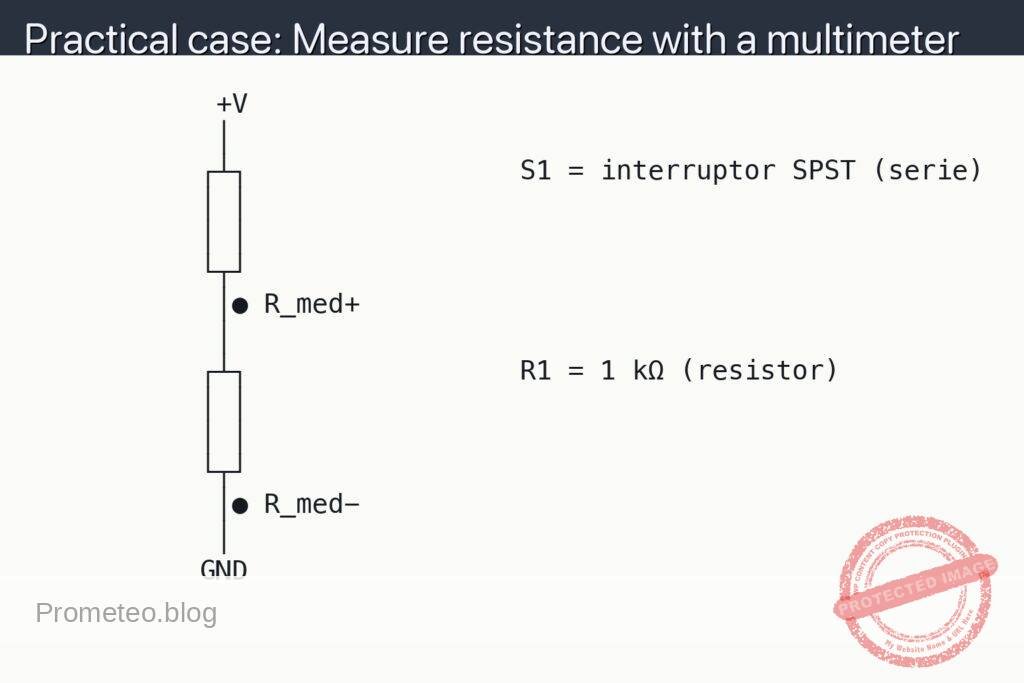
- Abbreviations used in the schematic:
- VM+IN: Red probe point to measure the input voltage (+V) against ground.
- VM+OUT: Red probe point to measure the divider output voltage against ground.
- VM−: Black probe point (ground reference).
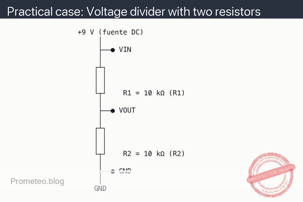
Schematic
                 +9 V (fuente DC)
                      │
                      ├──● VIN
                      │
                     ┌┴┐
                     │ │
                     │ │
                     └┬┘    R1 = 10 kΩ (R1)
                      │
                      ├──● VOUT
                      │
                     ┌┴┐
                     │ │
                     │ │
                     └┬┘    R2 = 10 kΩ (R2)
                      │
                      ├──● GND
                      │
                     GND
Measurements and tests
-
Verify the DC supply:
- Set the DMM to DC volts.
- Place the black probe on the VM− dot (GND).
- Place the red probe on the VM+IN dot (+V).
- Read Vin; it should match your source (e.g., ~9.0 V for a 9 V battery).
-
Measure the divider output:
- Keep the black probe on VM−.
- Move the red probe to VM+OUT.
- Record Vout. Theoretical value: Vout = Vin × R2 / (R1 + R2). With R1 = R2 = 10 kΩ, Vout ≈ 0.5 × Vin.
-
Estimate current through the chain (no ammeter needed):
- Compute I = Vin / (R1 + R2). For Vin = 9 V and total 20 kΩ, I ≈ 0.45 mA.
- This is also the current through each resistor (series path).
-
Account for resistor tolerance:
- If Vout differs slightly from theory, 5% or 1% tolerance and meter accuracy can explain it.
- Optionally measure each resistor with the DMM (power off) to see actual values and recompute Vout.
Theory in a minute
- A voltage divider scales a voltage using series resistors: Vout = Vin × R2 / (R1 + R2).
- Using equal resistors halves the input; choosing R2 smaller than R1 yields a lower fraction, and larger yields a higher fraction (but always below Vin).
Common mistakes
- Using too-low resistor values, causing unnecessary current draw and heating.
- Forgetting the common ground when measuring; always put the black probe on VM−.
- Misplacing the midpoint node so R1 and R2 are not truly in series.
Safety and good practices
- Do not short +V to GND; double-check connections before powering.
- Use kΩ-range resistors (e.g., 4.7 kΩ–100 kΩ) to keep current reasonable.
- Power off before changing resistor placements or measuring resistance.
Useful extensions
- Try R1 = 15 kΩ and R2 = 10 kΩ; predict and measure Vout = Vin × 10/(15+10) = 0.4 × Vin.
- Add a load resistor from Vout to GND (e.g., 10 kΩ) and observe how Vout drops due to loading; compute the equivalent R2 || Rload.
More Practical Cases on Prometeo.blog
Find this product and/or books on this topic on Amazon
As an Amazon Associate, I earn from qualifying purchases. If you buy through this link, you help keep this project running.
Quick Quiz

Telecommunications Electronics Engineer and Computer Engineer (official degrees in Spain).