Objective and use case
What you will build: A simple circuit with a 12 V incandescent lamp and an inductor in series to achieve a soft start by reducing the initial current spike.
What it is for
- Protect 12 V incandescent lamps in laboratory equipment when switching them on, extending their service life.
- Reduce stress on the power supply when connecting filament loads with high inrush current.
- Carry out basic tests of an inductor’s behavior in the transient regime of direct current.
- Simulate, on a small scale, the “soft start” effect used in higher‑power lighting systems.
- Visualize with a multimeter or clamp ammeter the difference in inrush current with and without a series inductor.
Expected result
- Measure a lower initial current with the inductor than without it (for example, a reduction of the I_LAMP peak on the order of 30–60%).
- Observe that the lamp brightness increases smoothly over about 0.2–0.5 s instead of turning on abruptly.
- Record a voltage drop in the inductor (V_L) that starts from a maximum value and decreases to almost 0 V in steady state.
- Verify that the 12 V supply voltage (V_SOURCE) remains close to 12 V without sudden drops during startup.
Target audience: Electronics students and trainee technicians; Level: Beginner–intermediate.
Architecture/flow: 12 V DC source → Series inductor → 12 V incandescent lamp → Measurement of I_LAMP and V_L during startup, comparing soft start with and without inductor.
Materials
- 1 × 12 V DC power supply (1–2 A minimum, regulated or bench supply).
- 1 × 12 V incandescent lamp (between 5 W and 10 W).
- 1 × Power inductor of approximately 10 mH, ≥ 2 A (choke / DC line filter type).
- 1 × Digital multimeter (with DC current measurement up to at least 2 A).
- 2 × Clip or banana cables for the supply.
- 4–6 × Flexible interconnection wires (preferably with alligator clips).
- 1 × Simple switch (optional, for repeated switching on and off of the circuit).
- 1 × Protoboard or connection base (optional; you can also “air‑wire” it carefully).
Wiring guide
Treat this section as the official connection specification. The schematic must implement exactly these connections.
- Connect the positive pole of the 12 V supply to terminal 1 of the inductor [L1].
- Connect terminal 2 of the inductor [L1] to node VA (lamp node).
- Connect one terminal of the lamp [LAMP1] to node VA.
- Connect the other terminal of the lamp [LAMP1] to the positive terminal of the ammeter (current input of the multimeter).
- Connect the negative terminal of the ammeter to the negative pole (GND) of the 12 V supply.
- If you use switch [SW1] to simplify tests:
- Connect the positive pole of the 12 V supply to contact 1 of [SW1].
- Connect contact 2 of [SW1] to terminal 1 of inductor [L1].
- Make sure there is no direct connection (just a wire) between the positive of the 12 V supply and GND without passing through [L1], [LAMP1] and the ammeter.
Schematic
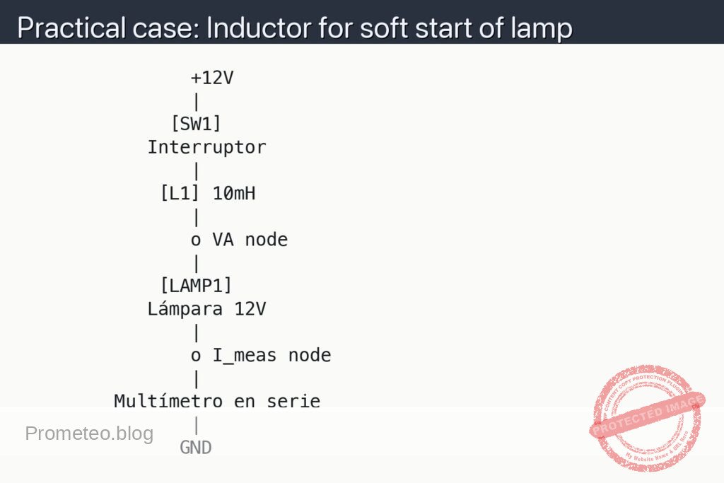
                +12V
                |
              [SW1]
            Interruptor
                |
             [L1] 10mH
                |
                o VA node
                |
             [LAMP1]
            Lámpara 12V
                |
                o I_meas node
                |
         Multímetro en serie
                |
               GND
Measurements and tests
-
Preparing the multimeter:
- Set the multimeter to DC current measurement mode (A DC).
- Connect the red probe to the current input connector (usually marked “10 A” or “A”).
- Connect the black probe to the common “COM” connector.
- Verify the appropriate range: if the lamp is 12 V / 10 W, the nominal current I_LAMP will be approximately I_LAMP ≈ P/V ≈ 10 W / 12 V ≈ 0.83 A; use a range of at least 2 A.
-
Measuring current I_LAMP without inductor (reference):
- Disconnect the inductor [L1] and connect the lamp [LAMP1] directly between +12 V and the ammeter in series to GND.
- Turn on the supply and observe the current I_LAMP (lamp current) during startup.
- Note the approximate maximum value (if the multimeter has peak capture, use it; if not, observe the first second after switching on).
-
Measuring current I_LAMP with inductor (practical case circuit):
- Reconnect the circuit as indicated in the wiring section (Supply → [SW1] → [L1] → [LAMP1] → Ammeter → GND).
- From the off state, close switch [SW1] and observe the I_LAMP current reading on the multimeter.
- Compare the peak value you observe with the case without inductor: you should see a more gradual increase.
- Repeat the on/off cycle several times, observing whether the current rises more smoothly (less abruptly) with the series inductor.
-
Measuring voltage drop across the inductor V_L:
- Switch the multimeter to DC voltage measurement mode (V DC).
- Connect the red probe to terminal 1 of [L1] (supply side) and the black probe to terminal 2 of [L1] (lamp side).
- Switch on the circuit and observe the voltage V_L at the instant of startup: you should see a small transient drop that decreases to almost 0 V when the current stabilizes.
-
Success criteria:
- The lamp still reaches its normal brightness after a short time.
- The initial current I_LAMP measured with the inductor is lower or takes longer to reach its nominal value than without inductor.
- The 12 V supply does not show an appreciable voltage drop (you can check with the multimeter between +12 V and GND).
- There are no abnormal hot spots on the inductor [L1] or on the wires at the test current used.
Common mistakes
- Connecting the ammeter in parallel instead of in series:
- This can cause a serious short circuit. The ammeter MUST always be in series with the load.
- Using an inductor with very low current rating:
- If [L1] cannot handle the lamp current, it may overheat or be damaged.
- Forgetting the switch and connecting/disconnecting wires with the supply on:
- Increases the risk of sparks, bad contacts and measurement errors.
- Confusing supply polarities:
- Although the inductor and lamp are not polarized, reversing polarity can affect other connected equipment or simultaneous measurements.
Safety
- Use a 12 V supply isolated from the mains, preferably a laboratory supply with overcurrent protection.
- Do not touch bare metal connections while handling the circuit: although 12 V is low, sparks or local heating can occur.
- Do not use this setup directly with mains voltage (230 V / 120 V). It is a practical case only for safe low voltage.
- Check the lamp power; do not exceed the maximum current that the supply and the inductor can handle.
Possible improvements and extensions
- Replace the lamp with a known power resistor and compare results:
- Makes it easier to calculate the theoretical transient response with L and R.
- Try different inductor values:
- 1 mH, 4.7 mH, 10 mH, 22 mH inductors and observe how the “softness” of the start‑up changes.
- Add a double switch:
- Position 1: lamp without inductor.
- Position 2: lamp with inductor.
- This way you can compare behavior more quickly.
- Record the current with a clamp ammeter or an oscilloscope with shunt:
- Allows you to see the shape of the inrush current and its time evolution in more detail.
More Practical Cases at Prometeo.blog
Find this product and/or books on this topic on Amazon
As an Amazon affiliate, I earn from qualifying purchases. If you buy through this link, you help support this project.
Quick quiz
More Practical Cases on Prometeo.blog

Telecommunications Electronics Engineer and Computer Engineer (official degrees in Spain).