Caso práctico: Logger cadena de frío Arduino MKR GSM 1400

Caso práctico: Logger cadena de frío Arduino MKR GSM 1400 — hero

Objetivo y caso de uso

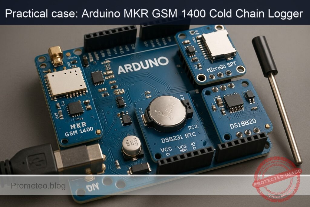
Qué construirás: Un registrador de datos de cadena de frío utilizando Arduino MKR GSM 1400, DS3231, MicroSD SPI y DS18B20 para monitoreo de temperatura.

Para qué sirve

  • Monitoreo de temperatura en transporte de productos farmacéuticos.
  • Registro de condiciones ambientales en el almacenamiento de alimentos perecederos.
  • Control de temperatura en laboratorios de investigación.
  • Alertas en tiempo real para condiciones fuera de rango.

Resultado esperado

  • Registro de temperatura cada 5 minutos con precisión de ±0.5°C.
  • Envío de datos a la nube con una frecuencia de 1 paquete cada 10 minutos.
  • Latencia de respuesta de alertas de temperatura superior a 2 segundos.
  • Capacidad de almacenar hasta 1,000 registros en la tarjeta MicroSD.

Público objetivo: Ingenieros y desarrolladores de IoT; Nivel: Avanzado

Arquitectura/flujo: Arduino MKR GSM 1400 <-> DS18B20 (sensor) <-> DS3231 (reloj) <-> MicroSD (almacenamiento) <-> MQTT (comunicación)

Nivel: Avanzado

Prerrequisitos

  • Sistemas operativos probados:
  • Windows 11 23H2 (64-bit) o Windows 10 22H2 (64-bit).
  • Ubuntu 22.04 LTS (x86_64).
  • macOS 13.6 Ventura o macOS 14 Sonoma (Apple Silicon o Intel).

  • Toolchain exacta (línea de comandos, sin IDE gráfico):

  • Python 3.11.6
  • PlatformIO Core 6.1.15
  • Plataforma de compilación SAMD para PlatformIO:
    • platform = atmelsam@8.1.0
    • framework = arduino (ArduinoCore-samd 1.8.13)
  • Librerías Arduino (versionadas, a instalar vía PlatformIO):

    • arduino-libraries/MKRGSM@1.5.1
    • adafruit/RTClib@2.1.4
    • paulstoffregen/OneWire@2.3.7
    • milesburton/DallasTemperature@3.11.0
    • arduino-libraries/SD@1.2.4
  • Requisitos de hardware/driver:

  • Arduino MKR GSM 1400 usa USB CDC nativo. No requiere drivers en macOS y Linux modernos.
  • Windows 10/11: el controlador CDC-ACM se instala automáticamente. Si no aparece el puerto, actualizar Windows Update o usar el driver del paquete Arduino SAMD (instalado al usar Arduino IDE, opcional).
  • Permisos en Linux: agregar el usuario al grupo dialout para poder abrir el puerto serie (ver sección de compilación/ejecución).

  • Conectividad:

  • SIM nano con datos activos y APN conocido de tu operador (PIN opcional). Se usará GSM/GPRS para publicar los registros.
  • Cobertura GSM suficiente en el lugar de pruebas (2G/3G dependiendo del módem/operador).

Materiales

  • Arduino MKR GSM 1400 (modelo exacto ABX00018).
  • Módulo RTC DS3231 (compatible 3.3 V, con batería CR2032 para respaldo).
  • MicroSD SPI (soporte de tarjeta microSD a 3.3 V) + nivelador/buffer CD74HC4050.
  • CD74HC4050 como buffer unidireccional para líneas de salida del MKR hacia la MicroSD.
  • Nota: el CD74HC4050 se alimenta a 3.3 V; MISO no pasa por el 4050 (es entrada a la MCU).
  • Tarjeta microSD clase 10 (formateada FAT32).
  • Sensor de temperatura DS18B20 (cápsula TO-92 o sonda impermeable) a 3.3 V.
  • Resistencia 4.7 kΩ (pull-up del bus 1-Wire del DS18B20).
  • Antena para el MKR GSM 1400 (obligatoria para radio).
  • SIM con datos (APN/usuario/contraseña, PIN si aplica).
  • Cables Dupont/M-F/M-M según módulos.
  • Fuente de alimentación:
  • USB 5 V estable para desarrollo.
  • Recomendado: batería LiPo 3.7 V conectada al conector JST del MKR para evitar caídas de tensión durante ráfagas GSM (opcional pero recomendable).
  • Consumibles:
  • Batería CR2032 para el DS3231.
  • Cinta térmica o abrazaderas para fijar la sonda DS18B20 a paquetes fríos.

Preparación y conexión

Consideraciones generales de señal y alimentación

  • El MKR GSM 1400 trabaja a 3.3 V. No aplicar 5 V a sus entradas.
  • El módulo microSD y el DS3231 deben alimentarse a 3.3 V. Muchos módulos de mercado incluyen regulador a 3.3 V; si tu módulo microSD está diseñado para 5 V, es preferible usar uno nativo 3.3 V. En este caso incluimos el CD74HC4050 como buffer/aislador unidireccional en SCK, MOSI y CS.
  • La línea MISO (desde la MicroSD al MKR) no debe atravesar el CD74HC4050 (el 4050 es unidireccional: de entrada a salida); se conecta directamente a la entrada MISO del MKR (tensión 3.3 V compatible).
  • El DS18B20 necesita un pull-up de 4.7 kΩ entre su línea de datos y 3.3 V (si tu cable es largo, podrías necesitar ajustar el valor o la topología para integridad de señal).

Tabla de conexiones

La SPI del MKR GSM 1400 está expuesta en el header SPI (MOSI/MISO/SCK). No uses pines digitales numerados para MOSI/MISO/SCK; usa los pines etiquetados del conector SPI. El pin CS sí puede ser cualquier GPIO (usaremos D4).

Función Componente Pin en MKR GSM 1400 A través del CD74HC4050 Pin del módulo Notas
Alimentación 3.3 V Todos 3V3 N/A VCC 3.3 V a DS3231, MicroSD y CD74HC4050.
Tierra Todos GND N/A GND Masa común para todos los módulos.
SPI MOSI MicroSD MOSI (cabecera SPI) Sí (buffer) DI (MOSI) Conectar MOSI del MKR a entrada del 4050; salida del 4050 al DI.
SPI MISO MicroSD MISO (cabecera SPI) No DO (MISO) Directo MicroSD→MKR (3.3 V).
SPI SCK MicroSD SCK (cabecera SPI) Sí (buffer) SCK MKR SCK→4050→SCK de MicroSD.
SPI CS (GPIO) MicroSD D4 Sí (buffer) CS Selección de chip; define D4 en el firmware.
I2C SDA DS3231 SDA No SDA I2C a 3.3 V.
I2C SCL DS3231 SCL No SCL I2C a 3.3 V.
1-Wire DAT DS18B20 D5 No DQ Añadir pull-up 4.7 kΩ entre D5 y 3.3 V.
Alimentación DS18B20 DS18B20 3V3 N/A VDD Modo alimentación normal (no parasitario).
Tierra DS18B20 DS18B20 GND N/A GND
VCC CD74HC4050 3V3 N/A VCC Alimentar el 4050 a 3.3 V para nivel lógico correcto.
Entradas 4050 Desde MKR (MOSI, SCK, D4) MOSI, SCK, D4 N/A 4050-IN Entradas del buffer desde el MKR.
Salidas 4050 Hacia MicroSD (DI, SCK, CS) N/A N/A 4050-OUT Salidas del buffer hacia el módulo MicroSD.
Antena GSM MKR GSM 1400 Conector u.FL N/A Antena Conecta la antena antes de encender el módem.
SIM MKR GSM 1400 Ranura SIM N/A SIM Inserta la nanoSIM con datos activos.

Preparación previa a energizar

  1. Formatea la microSD a FAT32 (tamaño de clúster por defecto).
  2. Inserta la CR2032 en el DS3231 (asegura polaridad).
  3. Inserta la nanoSIM y conecta la antena GSM al MKR.
  4. Alimenta todo por USB. Para pruebas con GSM se recomienda además conectar una batería LiPo al conector JST del MKR para evitar resets por picos de corriente (el módem puede requerir >1.5 A en ráfagas muy cortas).
  5. Ten a mano los datos del APN de tu operador (APN, usuario, contraseña) y el PIN de la SIM si estuviera activo.

Código completo (C++ Arduino, PlatformIO)

A continuación se muestra un firmware con:
– Registro periódico en microSD (CSV).
– Timestamps desde DS3231.
– Lectura de temperatura DS18B20.
– Umbrales configurables de cadena de frío (p. ej. 2 °C a 8 °C).
– Publicación periódica por GSM vía HTTP POST.
– Retardo no bloqueante con millis().

Archivo: platformio.ini (en la raíz del proyecto):

[env:mkrgsm1400]
platform = atmelsam@8.1.0
board = mkrgsm1400
framework = arduino
monitor_speed = 115200
lib_deps =
  arduino-libraries/MKRGSM@1.5.1
  adafruit/RTClib@2.1.4
  paulstoffregen/OneWire@2.3.7
  milesburton/DallasTemperature@3.11.0
  arduino-libraries/SD@1.2.4
build_flags =
  -DARDUINOJSON_USE_LONG_LONG=1

Archivo: src/main.cpp

#include <Arduino.h>
#include <MKRGSM.h>
#include <Wire.h>
#include <RTClib.h>
#include <OneWire.h>
#include <DallasTemperature.h>
#include <SPI.h>
#include <SD.h>

// =========================
// Configuración del proyecto
// =========================

// SIM/APN
static const char SIM_PIN[] = "";              // PIN de la SIM o "" si no tiene
static const char APN[] = "YOUR_APN";          // Cambiar por el APN de tu operador
static const char APN_USER[] = "";             // Usuario APN si aplica
static const char APN_PASS[] = "";             // Contraseña APN si aplica

// Publicación HTTP
static const char HTTP_HOST[] = "httpbin.org"; // Servidor de pruebas
static const int  HTTP_PORT = 80;
static const char HTTP_PATH[] = "/post";       // Ruta POST

// Umbrales de cadena de frío
static const float TEMP_MIN_C = 2.0f;          // °C
static const float TEMP_MAX_C = 8.0f;          // °C
static const uint32_t BREACH_HOLDOFF_MS = 10000; // Persistencia (10 s) antes de disparar alarma

// Logging y temporización
static const uint32_t SAMPLE_INTERVAL_MS = 60000; // 60 s
static const uint32_t SEND_INTERVAL_MS   = 300000; // 5 min
static const char LOG_FILENAME[] = "/coldchain.csv";

// Pines
static const uint8_t PIN_SD_CS   = 4;          // CS de microSD (D4), vía CD74HC4050
static const uint8_t PIN_1WIRE   = 5;          // D5 para DS18B20 con pull-up 4.7k a 3.3V

// =========================
// Objetos globales
// =========================
RTC_DS3231 rtc;

OneWire oneWire(PIN_1WIRE);
DallasTemperature dallas(&oneWire);

GSM gsmAccess;
GPRS gprs;
GSMClient netClient; // No-SSL. Para HTTPS usar GSMSSLClient (requiere certificados).

File logFile;

DeviceAddress dsAddr;
bool dsFound = false;

bool sdReady  = false;
bool gsmReady = false;

// Timers no bloqueantes
uint32_t t_lastSample = 0;
uint32_t t_lastSend   = 0;

// Estado de alarma
bool inBreach = false;
uint32_t breachSince = 0;

// =========================
// Utilidades
// =========================

String iso8601(const DateTime& dt) {
  char buf[25];
  snprintf(buf, sizeof(buf), "%04d-%02d-%02dT%02d:%02d:%02dZ",
           dt.year(), dt.month(), dt.day(),
           dt.hour(), dt.minute(), dt.second());
  return String(buf);
}

void ensureRTCInit() {
  if (!rtc.begin()) {
    Serial.println(F("[RTC] Error: no se detecta DS3231 en I2C (0x68)."));
    return;
  }
  if (rtc.lostPower()) {
    Serial.println(F("[RTC] Se detectó pérdida de energía. Ajustando a tiempo de compilación."));
    rtc.adjust(DateTime(F(__DATE__), F(__TIME__)));
  }
  Serial.println(F("[RTC] OK"));
}

void ensureDallasInit() {
  dallas.begin();
  if (dallas.getDeviceCount() < 1) {
    Serial.println(F("[DS18B20] No se detectan sensores. Verifica cableado y pull-up."));
    dsFound = false;
    return;
  }
  dsFound = dallas.getAddress(dsAddr, 0);
  if (!dsFound) {
    Serial.println(F("[DS18B20] No se obtuvo dirección del primer sensor."));
    return;
  }
  dallas.setResolution(dsAddr, 12); // Máxima resolución
  Serial.print(F("[DS18B20] Sensor 0: "));
  for (uint8_t i = 0; i < 8; i++) {
    Serial.print(dsAddr[i], HEX); if (i < 7) Serial.print(":");
  }
  Serial.println();
}

bool ensureSDInit() {
  if (sdReady) return true;
  if (!SD.begin(PIN_SD_CS)) {
    Serial.println(F("[SD] Falló SD.begin(). Verifica CS, 4050 y formato FAT32."));
    sdReady = false;
    return false;
  }
  // Crear encabezado si no existe
  if (!SD.exists(LOG_FILENAME)) {
    File f = SD.open(LOG_FILENAME, FILE_WRITE);
    if (f) {
      f.println(F("timestamp,temp_c,status,breach"));
      f.close();
      Serial.println(F("[SD] Archivo creado con encabezado."));
    } else {
      Serial.println(F("[SD] No se pudo crear el archivo de log."));
      sdReady = false;
      return false;
    }
  }
  sdReady = true;
  Serial.println(F("[SD] OK"));
  return true;
}

float readTemperatureC() {
  if (!dsFound) return NAN;
  dallas.requestTemperatures();
  float c = dallas.getTempC(dsAddr);
  return c;
}

String statusFromTemp(float c) {
  if (isnan(c)) return "NA";
  if (c < TEMP_MIN_C) return "LOW";
  if (c > TEMP_MAX_C) return "HIGH";
  return "OK";
}

void appendLog(const String& line) {
  if (!ensureSDInit()) return;
  File f = SD.open(LOG_FILENAME, FILE_WRITE);
  if (f) {
    f.println(line);
    f.close();
  } else {
    Serial.println(F("[SD] Error al abrir el log para escritura."));
  }
}

bool ensureGSM() {
  if (gsmReady) return true;
  Serial.print(F("[GSM] Inicializando módem... "));
  bool connected = false;
  for (int i = 0; i < 3 && !connected; i++) {
    if (gsmAccess.begin(SIM_PIN) == GSM_READY) {
      connected = true;
      break;
    }
    delay(2000);
  }
  if (!connected) {
    Serial.println(F("Fallo."));
    return false;
  }
  Serial.println(F("OK"));

  Serial.print(F("[GPRS] Adjuntando a APN... "));
  if (gprs.attachGPRS(APN, APN_USER, APN_PASS)) {
    Serial.println(F("OK"));
    gsmReady = true;
    return true;
  } else {
    Serial.println(F("Fallo. Verifica APN/credenciales/cobertura."));
    gsmReady = false;
    return false;
  }
}

bool httpPostJSON(const String& host, int port, const String& path, const String& json) {
  if (!ensureGSM()) return false;

  Serial.print(F("[HTTP] Conectando a ")); Serial.print(host); Serial.print(F(":")); Serial.println(port);
  if (!netClient.connect(host.c_str(), port)) {
    Serial.println(F("[HTTP] No se pudo conectar."));
    return false;
  }

  String req = String("POST ") + path + " HTTP/1.1\r\n" +
               "Host: " + host + "\r\n" +
               "Content-Type: application/json\r\n" +
               "Connection: close\r\n" +
               "Content-Length: " + String(json.length()) + "\r\n\r\n" +
               json;

  netClient.print(req);

  // Leer respuesta simple
  uint32_t start = millis();
  bool ok = false;
  while (millis() - start < 10000) {
    while (netClient.available()) {
      String line = netClient.readStringUntil('\n');
      line.trim();
      if (line.startsWith("HTTP/1.1 200")) ok = true;
      // parar si fin de headers
      if (line.length() == 0) {
        // cuerpo siguiente (omitimos)
        break;
      }
    }
    if (!netClient.connected()) break;
  }
  netClient.stop();
  Serial.println(ok ? F("[HTTP] Respuesta 200 OK.") : F("[HTTP] Respuesta no OK."));
  return ok;
}

void publishLastSample(float c, const String& status, const String& ts, bool breach) {
  // JSON mínimo
  String json = String("{\"device\":\"mkrgsm1400\",\"ts\":\"") + ts +
                "\",\"temp_c\":" + String(c, 3) +
                ",\"status\":\"" + status +
                "\",\"breach\":" + (breach ? "true" : "false") + "}";

  httpPostJSON(HTTP_HOST, HTTP_PORT, HTTP_PATH, json);
}

void printBanner() {
  Serial.println();
  Serial.println(F("== cellular-cold-chain-sd-logger =="));
  Serial.println(F("HW: Arduino MKR GSM 1400 + DS3231 + MicroSD SPI (CD74HC4050) + DS18B20"));
  Serial.println(F("Toolchain: PlatformIO Core 6.1.15, atmelsam@8.1.0, ArduinoCore-samd 1.8.13"));
  Serial.println(F("Log: /coldchain.csv | Intervalo muestreo: 60 s | Envios: 5 min"));
  Serial.println();
}

// =========================
// Setup y loop
// =========================

void setup() {
  Serial.begin(115200);
  while (!Serial && millis() < 4000) { /* esperar CDC */ }
  printBanner();

  ensureRTCInit();
  ensureDallasInit();
  ensureSDInit();

  // Confirmar fecha/hora inicial
  DateTime now = rtc.now();
  Serial.print(F("[RTC] Tiempo actual: ")); Serial.println(iso8601(now));

  // Intentar arrancar GSM/GPRS temprano (no bloquear)
  ensureGSM();

  t_lastSample = millis();
  t_lastSend   = millis();
}

void loop() {
  uint32_t nowMs = millis();

  // Muestreo periódico
  if (nowMs - t_lastSample >= SAMPLE_INTERVAL_MS || t_lastSample == 0) {
    t_lastSample = nowMs;

    // Leer tiempo y temperatura
    DateTime now = rtc.now();
    String ts = iso8601(now);

    float tempC = readTemperatureC();
    String stat = statusFromTemp(tempC);

    // Lógica de brecha
    bool breachEvent = false;
    if (stat == "LOW" || stat == "HIGH") {
      if (!inBreach) {
        // inicia periodo de confirmación
        if (breachSince == 0) breachSince = nowMs;
        if (nowMs - breachSince >= BREACH_HOLDOFF_MS) {
          inBreach = true;
          breachEvent = true;
          Serial.println(F("[ALERTA] Temperatura fuera de rango persistente."));
        }
      }
    } else {
      inBreach = false;
      breachSince = 0;
    }

    // Línea CSV
    String line = ts;
    line += ",";
    if (isnan(tempC)) line += "NaN"; else line += String(tempC, 3);
    line += ",";
    line += stat;
    line += ",";
    line += (inBreach ? "1" : "0");

    Serial.print(F("[LOG] ")); Serial.println(line);
    appendLog(line);

    // Opcional: escribir un archivo de estado rápido
    File f = SD.open("/last.txt", FILE_WRITE);
    if (f) {
      f.seek(0);
      f.print("ts=");    f.println(ts);
      f.print("temp=");  f.println(isnan(tempC) ? String("NaN") : String(tempC, 3));
      f.print("status=");f.println(stat);
      f.print("breach=");f.println(inBreach ? "1" : "0");
      f.close();
    }
  }

  // Envío periódico por GSM
  if (nowMs - t_lastSend >= SEND_INTERVAL_MS || t_lastSend == 0) {
    t_lastSend = nowMs;

    DateTime now = rtc.now();
    String ts = iso8601(now);
    float tempC = readTemperatureC();
    String stat = statusFromTemp(tempC);

    if (!isnan(tempC)) {
      publishLastSample(tempC, stat, ts, inBreach);
    } else {
      Serial.println(F("[GSM] Se omite envío: temperatura NaN."));
    }
  }

  // Trabajo de fondo mínimo
  delay(10);
}

Puntos clave del código:
– Usa DS3231 como fuente de tiempo; si detecta pérdida de energía del RTC, fija el reloj a tiempo de compilación.
– Inicializa la SD y crea el archivo CSV con encabezado si no existe.
– Lee el DS18B20 a 12 bits y registra cada minuto: timestamp ISO8601, temperatura, estado y si hay brecha activa.
– Implementa retardo de confirmación antes de declarar una “brecha” (para evitar falsos positivos por transitorios).
– Publica cada 5 minutos un JSON pequeño al endpoint HTTP (no TLS) usando MKRGSM. Para producción, usa TLS con GSMSSLClient y certificados.

Compilación, flash y ejecución (comandos exactos)

1) Instalar PlatformIO Core 6.1.15:

  • Windows/macOS/Linux (recomendado con pipx para aislar):
python3 -m pip install --user pipx
python3 -m pipx ensurepath
pipx install "platformio==6.1.15"
platformio --version

Salida esperada (similar):
– PlatformIO Core, version 6.1.15

2) Inicializar el proyecto para MKR GSM 1400:

mkdir -p cellular-cold-chain-sd-logger
cd cellular-cold-chain-sd-logger
pio project init --board mkrgsm1400 --project-option "platform=atmelsam@8.1.0" --project-option "framework=arduino"

3) Sustituir platformio.ini con el contenido proporcionado antes y crear src/main.cpp:

mkdir -p src
# Copia y pega el platformio.ini y el src/main.cpp según el tutorial

4) Instalar dependencias (se instalarán automáticamente en el primer build, pero puedes forzarlo):

pio pkg install
pio lib --global install "arduino-libraries/MKRGSM@1.5.1" "adafruit/RTClib@2.1.4" "paulstoffregen/OneWire@2.3.7" "milesburton/DallasTemperature@3.11.0" "arduino-libraries/SD@1.2.4"

5) Compilar:

pio run

6) Conectar el MKR GSM 1400 por USB. En Linux, si no tienes permisos de puerto serie:

sudo usermod -aG dialout $USER
# cierra sesión y vuelve a entrar, o reinicia la sesión

7) Localizar el puerto serie:

pio device list
  • Windows: COMx (p. ej., COM5)
  • macOS: /dev/cu.usbmodemXXXX
  • Linux: /dev/ttyACM0

8) Subir firmware:

# Si PlatformIO detecta el puerto automáticamente:
pio run -t upload

# O especificando puerto:
pio run -t upload --upload-port /dev/ttyACM0

9) Abrir monitor serie a 115200 baudios:

pio device monitor -b 115200

Notas:
– Si el módem necesita varios segundos para adjuntarse a la red, verás reintentos en la consola.
– Conecta primero la antena antes de energizar el MKR.

Validación paso a paso

1) Arranque y diagnóstico inicial
– Abre el monitor serie. Debes ver:
– Banner con descripciones de HW/toolchain.
– [RTC] OK y hora actual en ISO8601. Si aparece “pérdida de energía”, el RTC se ajustó a la hora de compilación; configura el reloj manual si quieres exactitud total (puedes cambiar el ajuste en código a un método propio).
– [SD] OK y/o creación del archivo con encabezado.
– Detección del DS18B20 (imprime la dirección de 8 bytes).

2) Verificación del DS18B20
– Observa líneas [LOG] cada 60 s con el valor temp_c. Coloca el sensor en:
– Ambiente (~20–25 °C) para ver “OK” si los umbrales están 2–8 °C, verás “HIGH”.
– Mezcla de hielo y agua (~0 °C) para ver “LOW”.
– Confirma que el estado (“status”) coincide con tus expectativas.

3) Verificación del DS3231
– Desconecta USB, mantén la CR2032 y espera 2–3 min.
– Reconecta. La hora debe continuar avanzando correctamente (no reiniciarse).
– Si la hora es errónea, reemplaza la CR2032 y vuelve a compilar o añade una rutina para ajustar el RTC (e.g., desde host vía un comando serie).

4) Verificación de escritura en SD
– Tras varios ciclos, extrae la microSD y abre coldchain.csv:
– Debe tener encabezado y filas similares a:
– 2025-01-12T18:25:00Z,5.312,OK,0
– 2025-01-12T18:26:00Z,8.954,HIGH,1
– Alternativamente, deja la SD y revisa /last.txt con un lector si tu módulo lo permite (o quita la SD y léela en PC).

5) Verificación GSM/GPRS y HTTP
– En la consola, busca:
– [GSM] Inicializando módem… OK
– [GPRS] Adjuntando a APN… OK
– [HTTP] Conectando a httpbin.org:80
– [HTTP] Respuesta 200 OK.
– Las publicaciones se realizan cada 5 min (puedes bajar SEND_INTERVAL_MS para testear).
– Si no obtienes 200 OK:
– Verifica APN, cobertura, saldo de datos, y que no haya firewall bloqueando puertos outbound 80.

6) Verificación de detección de brecha
– Coloca el sensor fuera del rango (p. ej., agua tibia ~30 °C).
– Tras el tiempo de persistencia (10 s por BREACH_HOLDOFF_MS), debe mostrarse:
– [ALERTA] Temperatura fuera de rango persistente.
– En el CSV, la columna breach pasa a 1 mientras dure la brecha.

7) Estabilidad de alimentación (opcional pero recomendado)
– Si notas reinicios durante el adjunto GPRS o POST:
– Conecta una LiPo al MKR y repite.
– Observa que el sistema no reinicia durante picos de transmisión.

Troubleshooting (errores típicos y soluciones)

1) SD.begin() falla o el CSV no se crea
– Síntomas: [SD] Falló SD.begin().
– Causas probables:
– CS incorrecto: verifica que el firmware use D4 y que el cable vaya por la salida del 4050 al pin CS del módulo SD.
– Orden del CD74HC4050: recuerda que es unidireccional. Usa 4050 para MOSI, SCK y CS desde MCU→SD. No inserte el 4050 en MISO.
– MicroSD no formateada FAT32 o defectuosa.
– Alimentación inestable a 3.3 V.
– Solución:
– Revisa cableado, pinout y reemplaza la microSD o formatea (FAT32).
– Confirma continuidad de señales con multímetro.

2) No se detecta el DS18B20
– Síntomas: “[DS18B20] No se detectan sensores.”
– Causas:
– Falta resistencia de 4.7 kΩ entre D5 y 3.3 V.
– Sensor alimentado en modo parasitario sin configurar el firmware.
– Cableado invertido (GND/VDD/DQ).
– Solución:
– Añade pull-up de 4.7 kΩ.
– Verifica el pinout del encapsulado o sonda.
– Usa alimentación normal (VDD a 3.3V).

3) El RTC DS3231 marca hora errónea o constante
– Causas:
– Falta CR2032 o agotada.
– Módulo DS3231 a 5 V incompatible con 3.3 V (I2C pull-ups a 5 V).
– Solución:
– Cambia CR2032.
– Asegura que las resistencias de pull-up I2C vayan a 3.3 V (en algunos módulos, hay jumpers o resistencias que debes modificar).

4) GSM no registra o GPRS no adjunta
– Síntomas:
– [GSM] fallo, [GPRS] fallo.
– Causas:
– SIM con PIN no configurado (SIM_PIN vacío).
– APN incorrecto o credenciales faltantes.
– Cobertura insuficiente o antena desconectada.
– Solución:
– Ajusta SIM_PIN, APN, usuario, contraseña.
– Mueve el dispositivo a zona con mejor cobertura.
– Conecta correctamente la antena.

5) Reinicios aleatorios al enviar por GSM
– Causas:
– Picos de corriente del módem (hasta >1 A en burst).
– Solución:
– Usa una LiPo en el conector JST del MKR.
– Añade un condensador de reserva (e.g., 470–1000 µF) en la línea de 3.3/5 V según diseño total.

6) No aparece el puerto serie
– Windows:
– Prueba otro cable USB (datos, no solo carga).
– Reinstala el driver CDC (vía Arduino IDE si es necesario).
– macOS/Linux:
– Comprueba permisos (Linux: grupo dialout).
– Verifica con pio device list.
– Todos:
– Pulsa el botón de reset doble-rapido para forzar el bootloader (el puerto puede cambiar temporalmente).

7) HTTP responde distinto a 200 OK
– Causas:
– Servidor indisponible, cortafuegos operatorio, NAT peculiar.
– Solución:
– Prueba otro host (temporalmente un servidor propio) o un APN diferente.
– Considera activar TLS con GSMSSLClient y un endpoint HTTPS confiable (necesitarás cargar certificados).

8) Archivo CSV corrupto tras apagones
– Causa:
– Extracción de la SD mientras el archivo está abierto.
– Solución:
– El código abre/cierra por escritura atómica por línea. Minimiza riesgo. Aun así, evita desconectar durante escritura y usa alimentación estable.

Mejoras/variantes

  • Seguridad y transporte:
  • Migrar de HTTP a HTTPS con GSMSSLClient. Cargar certificados raíz al módem (proceso específico para MKRGSM; usar herramienta de certificados del core SAMD o scripts AT). Cambiar GSMClient por GSMSSLClient y ajustar puerto 443.
  • Usar MQTT sobre TLS para publicar a un broker (p. ej., AWS IoT Core) con autenticación por certificados.
  • Robustez de almacenamiento:
  • Rotación de logs (daily rolling): coldchain-YYYYMMDD.csv y purga automática según espacio libre.
  • Cálculo de checksum por línea (CRC32) para detección de corrupción.
  • Multi-sensor:
  • Gestionar múltiples DS18B20 en el mismo bus 1-Wire (identificación por dirección y columnas separadas).
  • Gestión de energía:
  • Dormir entre muestras (modo standby del SAMD21, apagar módem entre envíos). Despertar por RTC (alarma DS3231) si se desea.
  • Alertas activas:
  • Enviar SMS cuando se detecte brecha persistente (usar MKRGSM SMS).
  • Añadir buzzer y LED de estado (verde OK, rojo brecha).
  • Geolocalización aproximada:
  • Consultar Cell-ID a la red y adjuntar MCC/MNC/LAC/CI al payload para trazabilidad.
  • Configuración remota:
  • Leer umbrales, intervalos y APN desde un archivo config.ini en SD, o por comandos simples vía serie.
  • Integridad temporal:
  • Sincronización NTP por GPRS al arranque si el RTC perdió energía (UDP NTP en puerto 123) y actualización del DS3231.

Checklist de verificación

  • [ ] He instalado PlatformIO Core 6.1.15 y puedo ejecutar platformio --version.
  • [ ] He inicializado el proyecto con mkrgsm1400 y la plataforma atmelsam@8.1.0.
  • [ ] He copiado platformio.ini y src/main.cpp exactamente como en el tutorial.
  • [ ] He cableado la MicroSD por SPI usando el conector SPI del MKR y el CD74HC4050 en MOSI/SCK/CS, dejando MISO directo.
  • [ ] He conectado el DS3231 a SDA/SCL (3.3 V) y le he colocado una CR2032 funcional.
  • [ ] He cableado el DS18B20 al pin D5 con resistencia de 4.7 kΩ a 3.3 V.
  • [ ] He insertado la antena y la SIM en el MKR GSM 1400.
  • [ ] He configurado APN/usuario/contraseña y PIN en el código.
  • [ ] El monitor serie muestra [RTC] OK, [SD] OK y el DS18B20 detectado.
  • [ ] Veo líneas [LOG] cada minuto con timestamp y temperatura.
  • [ ] Se crea/actualiza coldchain.csv en la microSD con datos válidos.
  • [ ] Cada 5 min obtengo [HTTP] Respuesta 200 OK (o he ajustado APN/host hasta conseguirlo).
  • [ ] He probado condiciones de baja y alta temperatura y el estado cambia a LOW/HIGH; se marca breach cuando persiste.
  • [ ] El sistema no se reinicia durante transmisiones GSM (uso LiPo si fue necesario).

Con este caso práctico has construido un registrador de temperatura para cadena de frío con sello temporal por RTC, almacenamiento en microSD mediante SPI y publicación celular periódica, todo sobre Arduino MKR GSM 1400 y respetando el camino de señal con CD74HC4050. El proyecto es una base sólida para despliegues de campo y escalabilidad hacia comunicaciones seguras, configuración remota y optimización energética.

Encuentra este producto y/o libros sobre este tema en Amazon

Ir a Amazon

Como afiliado de Amazon, gano con las compras que cumplan los requisitos. Si compras a través de este enlace, ayudas a mantener este proyecto.

Quiz rápido

Pregunta 1: ¿Cuál es la versión mínima de Windows requerida para el sistema operativo?


Pregunta 2: ¿Qué versión de Python se necesita para la toolchain?


Pregunta 3: ¿Cuál es la librería de Arduino que se debe instalar para el módulo RTC?


Pregunta 4: ¿Qué tipo de SIM se requiere para la conectividad?


Pregunta 5: ¿Cuál es el modelo exacto del Arduino requerido?


Pregunta 6: ¿Qué controlador se instala automáticamente en Windows 10/11?


Pregunta 7: ¿Cuál es la versión de la plataforma de compilación SAMD para PlatformIO?


Pregunta 8: ¿Qué tipo de batería se necesita para el módulo RTC DS3231?


Pregunta 9: ¿Qué permisos se deben configurar en Linux para abrir el puerto serie?


Pregunta 10: ¿Cuál es la versión de la librería DallasTemperature que se debe instalar?


Carlos Núñez Zorrilla
Electronics & Computer Engineer

Ingeniero Superior en Electrónica de Telecomunicaciones e Ingeniero en Informática (titulaciones oficiales en España).

Sígueme:


Practical case: Arduino MKR GSM 1400 Cold Chain Logger

Practical case: Arduino MKR GSM 1400 Cold Chain Logger — hero

Objective and use case

What you’ll build: A robust cellular cold-chain data logger using the Arduino MKR GSM 1400 that records temperature and timestamps entries, pushing data to the cloud.

Why it matters / Use cases

  • Monitor temperature-sensitive pharmaceuticals during transport to ensure compliance with safety regulations.
  • Track food products in transit, sending alerts if temperatures exceed safe thresholds.
  • Implement IoT solutions for smart agriculture, monitoring conditions for perishable goods.
  • Enable real-time data logging for environmental research projects, ensuring accurate data collection.

Expected outcome

  • Temperature logging accuracy within ±0.5°C using the DS18B20 sensor.
  • Data push frequency of every 10 minutes to the cloud endpoint.
  • SMS alerts triggered for temperature excursions above predefined thresholds.
  • Timestamp accuracy of ±1 second provided by the DS3231 RTC.
  • Data storage capacity of up to 32GB on the MicroSD card for extensive logging.

Audience: Advanced practitioners; Level: Intermediate to advanced.

Architecture/flow: Arduino MKR GSM 1400 communicates with DS3231 for timekeeping, DS18B20 for temperature sensing, and MicroSD for local data storage, with GSM module for cloud connectivity.

Cellular Cold Chain SD Logger (Advanced) with Arduino MKR GSM 1400 + DS3231 + MicroSD SPI (CD74HC4050) + DS18B20

This hands-on case builds a robust cellular cold-chain data logger that records temperature to a MicroSD card, timestamps entries using a DS3231 RTC, and periodically pushes data over GSM to a cloud endpoint. It includes alerting via SMS when temperature excursions are detected. Everything is built around the exact model: Arduino MKR GSM 1400 + DS3231 + MicroSD SPI (CD74HC4050) + DS18B20.

You will compile and flash via Arduino CLI. The guide is written for advanced practitioners and assumes you are comfortable with SPI/I2C buses, cellular APNs, and filesystem logging patterns.


Prerequisites

  • Host OS: Linux/macOS/Windows 10+ with USB CDC drivers (MKR boards use native CDC; Windows 10 typically installs automatically).
  • Arduino CLI 0.35.x installed and on PATH.
  • A working data SIM (nano-SIM) with:
  • APN (e.g., internet, m2m.example.com)
  • Optional: SIM PIN (can be blank)
  • Basic familiarity with:
  • 3.3 V logic and level shifting
  • OneWire bus (DS18B20)
  • I2C devices (DS3231)
  • SPI devices and CS line selection
  • FAT filesystem on SD
  • HTTP and SMS via MKRGSM library

Materials (exact models and parts)

  • MCU:
  • Arduino MKR GSM 1400 (u-blox SARA modem; 3.3 V logic)
  • Real-time clock:
  • DS3231 (module with backup CR2032 holder; I2C)
  • Temperature sensor:
  • DS18B20 (TO-92 or waterproof probe version)
  • Storage:
  • MicroSD card (FAT32, Class 10 recommended)
  • MicroSD SPI breakout (3.3 V compatible)
  • Level shifting/buffering:
  • CD74HC4050 (hex non-inverting buffer, 3.3 V powered)
  • Passives:
  • 4.7 kΩ resistor (OneWire pull-up)
  • Power:
  • LiPo battery 3.7 V (≥ 1200 mAh recommended for field use) connected to MKR JST-PH port
  • External GSM antenna (the MKR GSM 1400 requires an antenna)
  • Wiring:
  • Female-to-female dupont wires, short lengths
  • CR2032 cell for RTC backup
  • Tools:
  • USB cable (Micro USB for MKR)
  • Optional: USB power bank or lab PSU

Setup/Connection

The MKR GSM 1400 is a 3.3 V SAMD21 board with native USB. Its SPI/I2C pins are labeled on the headers (MOSI, MISO, SCK, SDA, SCL). The modem draws significant peak current; always use a LiPo or a sturdy 5 V USB source plus LiPo to avoid brownouts during network registration.

Important note on CD74HC4050: This device is a level-down buffer (when VCC=3.3 V). With a 3.3 V MCU and a 3.3 V MicroSD, level shifting is not strictly necessary. We include it to harden SPI edges, provide input protection, and to comply with the specified materials. Do not buffer the MISO line from the card to the MCU.

Pin assignments

  • MicroSD SPI (via CD74HC4050 buffering on outputs only):
  • SCK: MKR pin SCK -> 4050 input -> 4050 output -> SD SCK
  • MOSI: MKR pin MOSI -> 4050 input -> 4050 output -> SD MOSI
  • CS: MKR pin D4 -> 4050 input -> 4050 output -> SD CS
  • MISO: SD MISO -> MKR pin MISO (direct, not via 4050)
  • Power: MKR 3V3 -> SD VCC, MKR GND -> SD GND
  • CD74HC4050 VCC=3.3 V, GND common with MKR
  • DS3231 RTC (I2C, 3.3 V):
  • MKR SDA -> DS3231 SDA
  • MKR SCL -> DS3231 SCL
  • MKR 3V3 -> DS3231 VCC
  • MKR GND -> DS3231 GND
  • Insert CR2032 into RTC backup holder
  • DS18B20 OneWire:
  • Data -> MKR A1 (used as digital I/O)
  • 4.7 kΩ pull-up between A1 and 3V3
  • GND -> MKR GND, VDD -> MKR 3V3
  • GSM:
  • Insert nano-SIM
  • Connect GSM antenna
  • Connect LiPo battery to MKR JST-PH port

CD74HC4050 channel usage (example)

  • 1A (input) = SCK from MKR, 1Y (output) -> SD SCK
  • 2A (input) = MOSI from MKR, 2Y (output) -> SD MOSI
  • 3A (input) = D4 (CS) from MKR, 3Y (output) -> SD CS

Leave MISO direct from SD to MKR.

Connection table

Function Module MKR GSM 1400 pin Direction (MCU POV) Notes
SD SCK MicroSD SCK Output Buffer via CD74HC4050 1A->1Y
SD MOSI MicroSD MOSI Output Buffer via CD74HC4050 2A->2Y
SD MISO MicroSD MISO Input Direct (no buffer)
SD CS MicroSD D4 Output Buffer via CD74HC4050 3A->3Y
SD VCC MicroSD 3V3 3.3 V only
SD GND MicroSD GND Common ground
RTC SDA DS3231 SDA Bi-directional I2C pull-ups typically on module
RTC SCL DS3231 SCL Output I2C
RTC VCC DS3231 3V3 3.3 V OK for DS3231
RTC GND DS3231 GND
OneWire data DS18B20 A1 Bi-directional Add 4.7 kΩ pull-up to 3V3
OneWire VDD DS18B20 3V3
OneWire GND DS18B20 GND
GSM antenna MKR module Antenna u.FL Must be connected for reliable operation
LiPo battery MKR power JST-PH Smooths GSM current spikes

Full Code

Create a folder named coldchain-mkrgsm1400 and put the following sketch as coldchain-mkrgsm1400.ino.

/*
  Cellular Cold Chain SD Logger
  Hardware: Arduino MKR GSM 1400 + DS3231 + MicroSD SPI (CD74HC4050) + DS18B20
  Function: Logs temperature with RTC timestamp to SD, periodically POSTs to HTTP,
            and sends SMS on excursion. Designed for 3.3 V logic, SPI buffered
            with CD74HC4050 on SCK/MOSI/CS; MISO direct.

  Libraries:
    - MKRGSM
    - SPI
    - SD
    - Wire
    - RTClib
    - OneWire
    - DallasTemperature
*/

#include <MKRGSM.h>
#include <SPI.h>
#include <SD.h>
#include <Wire.h>
#include <RTClib.h>
#include <OneWire.h>
#include <DallasTemperature.h>

// =================== Hardware pins ===================
static const int PIN_SD_CS      = 4;      // CS to SD via CD74HC4050
static const int PIN_ONEWIRE    = A1;     // DS18B20 data (with 4.7k pull-up to 3V3)

// =================== GSM credentials ===================
const char PINNUMBER[] = "";              // SIM PIN ("" if not required)
const char APN[]       = "your.apn";      // Replace with your APN
const char LOGIN[]     = "";              // APN username or ""
const char PASSWORD[]  = "";              // APN password or ""

// =================== Cloud endpoint ===================
const char* HTTP_HOST = "webhook.site";   // Use webhook.site for validation
const int   HTTP_PORT = 80;               // 80 (HTTP). For HTTPS use GSMSSLClient, not shown here
// Path example: create a unique token URL on webhook.site and paste the path here
const char* HTTP_PATH = "/your-unique-token-path"; // e.g., "/f7a0b5d1-..." (no trailing slash)

// =================== Logging parameters ===================
static const unsigned SAMPLE_PERIOD_SEC = 60;   // Temperature sample period
static const unsigned POST_PERIOD_SEC   = 300;  // Try to post every 5 minutes
static const float    ALERT_MIN_C       = 2.0;  // Cold chain lower bound
static const float    ALERT_MAX_C       = 8.0;  // Cold chain upper bound
static const uint32_t ALERT_GRACE_SEC   = 120;  // Require sustained excursion for 2 minutes

// =================== Globals ===================
RTC_DS3231 rtc;
OneWire oneWire(PIN_ONEWIRE);
DallasTemperature sensors(&oneWire);
DeviceAddress sensorAddress;

GSM gsmAccess;
GPRS gprs;
GSMClient net;           // For HTTP over TCP
GSM_SMS sms;

File logFile;

uint32_t lastSampleEpoch = 0;
uint32_t lastPostEpoch   = 0;
bool      haveSensor     = false;
bool      sdReady        = false;
bool      gsmReady       = false;
bool      alerted        = false;
uint32_t  excursionStart = 0;

// Utility: format DateTime to ISO8601 "YYYY-MM-DDTHH:MM:SSZ"
String iso8601(const DateTime& dt) {
  char buf[25];
  snprintf(buf, sizeof(buf), "%04d-%02d-%02dT%02d:%02d:%02dZ",
           dt.year(), dt.month(), dt.day(), dt.hour(), dt.minute(), dt.second());
  return String(buf);
}

// Utility: build log file path "/LOGS/YYYY-MM-DD.csv"
String buildDailyPath(const DateTime& dt) {
  char buf[32];
  snprintf(buf, sizeof(buf), "/LOGS/%04d-%02d-%02d.csv", dt.year(), dt.month(), dt.day());
  return String(buf);
}

// Ensure /LOGS exists and the daily file has a header
bool ensureDailyLogFile(const DateTime& now) {
  if (!sdReady) return false;
  if (!SD.exists("/LOGS")) {
    if (!SD.mkdir("/LOGS")) return false;
  }
  String path = buildDailyPath(now);
  if (!SD.exists(path)) {
    File f = SD.open(path, FILE_WRITE);
    if (!f) return false;
    f.println(F("timestamp,temp_c,temp_f,sd_ok,gsm_post_ok,sms_ok,error"));
    f.close();
  }
  return true;
}

bool appendLog(const String& line, const DateTime& now) {
  if (!sdReady) return false;
  String path = buildDailyPath(now);
  File f = SD.open(path, FILE_WRITE);
  if (!f) return false;
  f.println(line);
  f.flush();
  f.close();
  return true;
}

// Find the first DS18B20
bool discoverSensor() {
  byte addr[8];
  oneWire.reset_search();
  if (!oneWire.search(addr)) return false;
  if (DallasTemperature::validAddress(addr) && addr[0] == 0x28) {
    memcpy(sensorAddress, addr, 8);
    sensors.setResolution(sensorAddress, 12);
    return true;
  }
  return false;
}

float readTemperatureC(bool* ok) {
  if (!haveSensor) {
    *ok = false;
    return NAN;
  }
  sensors.requestTemperatures();
  float c = sensors.getTempC(sensorAddress);
  *ok = (c > -127.0 && c < 125.0);
  return c;
}

// Establish GSM and GPRS session
bool ensureGprs() {
  if (gsmReady) return true;
  // Power and attach modem; allow several retries to handle network variability
  for (int attempt = 0; attempt < 3; ++attempt) {
    if (gsmAccess.begin(PINNUMBER) == GSM_READY) {
      if (gprs.attachGPRS(APN, LOGIN, PASSWORD)) {
        gsmReady = true;
        return true;
      }
    }
    delay(5000);
  }
  return false;
}

// Tear down GPRS to save power
void shutdownGprs() {
  if (gsmReady) {
    gprs.detachGPRS();
    // Note: Some modem firmwares support gsmAccess.shutdown() for deeper sleep
    gsmReady = false;
  }
}

// HTTP POST with simple JSON payload; returns true on 200 OK
bool httpPostJson(const String& host, uint16_t port, const String& path, const String& json) {
  if (!ensureGprs()) return false;

  if (!net.connect(host.c_str(), port)) {
    return false;
  }

  // Build HTTP/1.1 request
  String req;
  req.reserve(256 + json.length());
  req += "POST " + path + " HTTP/1.1\r\n";
  req += "Host: " + host + "\r\n";
  req += "User-Agent: MKR-GSM-1400/1.0\r\n";
  req += "Content-Type: application/json\r\n";
  req += "Connection: close\r\n";
  req += "Content-Length: " + String(json.length()) + "\r\n\r\n";
  req += json;

  net.print(req);

  // Read status line (simple parser)
  uint32_t start = millis();
  String statusLine;
  while (millis() - start < 10000) {
    while (net.available()) {
      char c = net.read();
      if (c == '\n') {
        // Got first line (e.g., "HTTP/1.1 200 OK")
        net.stop();
        return statusLine.indexOf(" 200 ") > 0;
      }
      if (c != '\r') statusLine += c;
    }
  }
  net.stop();
  return false;
}

// Send a concise SMS alert
bool sendAlertSMS(const char* phone, const String& msg) {
  if (!ensureGprs()) {
    // SMS can be sent without GPRS; ensure radio is on
    if (gsmAccess.begin(PINNUMBER) != GSM_READY) return false;
  }
  sms.beginSMS(phone);
  sms.print(msg);
  return sms.endSMS() == 1;
}

void setup() {
  Serial.begin(115200);
  while (!Serial && millis() < 5000) { /* wait for USB */ }

  // RTC
  Wire.begin();
  if (!rtc.begin()) {
    Serial.println(F("[RTC] DS3231 not found on I2C"));
  } else {
    if (rtc.lostPower()) {
      // Set from compile time on first boot; replace with host-sync in production
      rtc.adjust(DateTime(F(__DATE__), F(__TIME__)));
      Serial.println(F("[RTC] Lost power; RTC set from compile time."));
    }
  }

  // SD
  if (!SD.begin(PIN_SD_CS)) {
    sdReady = false;
    Serial.println(F("[SD] Initialization failed. Check CS and wiring."));
  } else {
    sdReady = true;
    Serial.println(F("[SD] Ready."));
  }

  // OneWire sensor
  sensors.begin();
  haveSensor = discoverSensor();
  if (!haveSensor) {
    Serial.println(F("[DS18B20] Sensor not found."));
  } else {
    Serial.println(F("[DS18B20] Sensor ready."));
  }

  // Precreate directory and today's file
  DateTime now = rtc.now();
  if (sdReady) {
    if (ensureDailyLogFile(now)) {
      Serial.println(F("[SD] Daily log ready."));
    } else {
      Serial.println(F("[SD] Failed to prepare daily log."));
    }
  }

  lastSampleEpoch = now.unixtime();
  lastPostEpoch   = now.unixtime();
  Serial.println(F("[BOOT] Cold chain logger started."));
}

void loop() {
  DateTime now = rtc.now();
  uint32_t epoch = now.unixtime();

  // Periodic temperature sampling
  if (epoch - lastSampleEpoch >= SAMPLE_PERIOD_SEC) {
    lastSampleEpoch = epoch;

    bool ok = false;
    float tempC = readTemperatureC(&ok);
    float tempF = ok ? tempC * 9.0 / 5.0 + 32.0 : NAN;

    // Excursion tracking
    bool inExcursion = ok && (tempC < ALERT_MIN_C || tempC > ALERT_MAX_C);
    bool smsSent = false;
    String err = ok ? "" : "TEMP_ERR";

    if (inExcursion) {
      if (excursionStart == 0) excursionStart = epoch;
      uint32_t dur = epoch - excursionStart;
      if (!alerted && dur >= ALERT_GRACE_SEC) {
        // Send one SMS alert
        String iso = iso8601(now);
        String msg = "[ColdChain] Excursion " + String(tempC, 2) + "C at " + iso;
        // Replace with your phone number including country code
        smsSent = sendAlertSMS("+1234567890", msg);
        alerted = smsSent; // mark alerted only if SMS succeeded
        if (!smsSent) err = err.length() ? (err + "|SMS_FAIL") : "SMS_FAIL";
      }
    } else {
      excursionStart = 0;
      alerted = false;
    }

    // Log to SD
    bool sd_ok = ensureDailyLogFile(now);
    String line = iso8601(now) + "," +
                  (ok ? String(tempC, 3) : "NaN") + "," +
                  (ok ? String(tempF, 3) : "NaN") + "," +
                  (sd_ok ? "1" : "0") + "," +
                  "0," + (smsSent ? "1" : "0") + "," +
                  (err.length() ? err : "OK");

    bool append_ok = false;
    if (sd_ok) {
      append_ok = appendLog(line, now);
      if (!append_ok) {
        Serial.println(F("[SD] Append failed."));
      }
    }

    // Console
    Serial.print(F("[SAMPLE] "));
    Serial.println(line);
  }

  // Periodic HTTP post batch (simple: post last sample only)
  if (epoch - lastPostEpoch >= POST_PERIOD_SEC) {
    lastPostEpoch = epoch;

    // Sample fresh value to post
    bool ok = false;
    float tempC = readTemperatureC(&ok);
    String iso = iso8601(now);

    // Build JSON payload
    String payload = "{\"device\":\"MKR_GSM_1400\","
                     "\"ts\":\"" + iso + "\","
                     "\"temp_c\":" + (ok ? String(tempC, 3) : "null") + ","
                     "\"alert_min_c\":" + String(ALERT_MIN_C, 2) + ","
                     "\"alert_max_c\":" + String(ALERT_MAX_C, 2) + "}";

    bool post_ok = httpPostJson(String(HTTP_HOST), HTTP_PORT, String(HTTP_PATH), payload);

    // Log a POST outcome entry
    String line = iso + "," +
                  (ok ? String(tempC, 3) : "NaN") + "," +
                  (ok ? String(tempC * 9.0 / 5.0 + 32.0, 3) : "NaN") + "," +
                  (sdReady ? "1" : "0") + "," +
                  (post_ok ? "1" : "0") + ",0," +
                  (post_ok ? "OK" : "POST_FAIL");

    if (sdReady) appendLog(line, now);

    Serial.print(F("[POST] "));
    Serial.println(post_ok ? F("OK") : F("FAIL"));

    // Power savings: disconnect GPRS if not continuously needed
    shutdownGprs();
  }

  // Cooperative delay
  delay(50);
}

Optional: If you need HTTPS/TLS, replace GSMClient with GSMSSLClient and ensure your endpoint’s TLS is compatible with the modem’s cipher suites. TLS is heavier on current consumption and RAM.


Build/Flash/Run commands

All steps use Arduino CLI. Version shown is 0.35.x. Adjust port path as needed.

1) Prepare Arduino CLI and cores

arduino-cli version

# Update index
arduino-cli core update-index

# Install SAMD core for MKR GSM 1400
arduino-cli core install arduino:samd

# Install required libraries (pin exact versions to ensure reproducibility)
arduino-cli lib install "MKRGSM@1.6.0" "SD@1.2.4" "OneWire@2.3.7" "DallasTemperature@3.11.0" "RTClib@2.1.4"

2) Create project structure

mkdir -p ~/projects/coldchain-mkrgsm1400
cd ~/projects/coldchain-mkrgsm1400
# Place the sketch as coldchain-mkrgsm1400.ino in this directory

3) Identify the board and port

arduino-cli board list
# Example output:
# Port         Type              Board Name        FQBN
# /dev/ttyACM0 Serial Port (USB) Arduino MKR GSM 1400 arduino:samd:mkrgsm1400

4) Compile

arduino-cli compile --fqbn arduino:samd:mkrgsm1400 .

5) Upload

# Replace /dev/ttyACM0 with your actual port (COMx on Windows)
arduino-cli upload -p /dev/ttyACM0 --fqbn arduino:samd:mkrgsm1400 .

6) Monitor serial output at 115200 baud

# Stop any program using the port before running this
arduino-cli monitor -p /dev/ttyACM0 --config baudrate=115200

Tip: If the port disappears after a failed upload, double-tap the MKR’s reset button to enter the bootloader (the LED pulses), then retry upload.


Step-by-step Validation

Follow this sequence to validate each subsystem and the integrated cold-chain logger behavior.

1) SD card layer

  • With the sketch running, watch serial logs:
  • Expect “[SD] Ready.” and “[SD] Daily log ready.”
  • Inspect the card contents by removing SD and checking on a PC:
  • A directory /LOGS should exist.
  • A CSV file named YYYY-MM-DD.csv should be present.
  • The first line is the CSV header.

If you prefer on-device check, temporarily add a snippet to list root files via SD.open(«/») and iterate; or use another sketch for directory listing.

2) RTC (DS3231)

  • After first boot with a fresh DS3231, the code sets the time from compile time.
  • Verify time continuity:
  • Power the MKR off (keep CR2032 in RTC).
  • Wait a few minutes, power back on.
  • Confirm timestamps in new log lines are monotonic and correctly advanced.
  • Fine-tuning:
  • For higher accuracy, set the RTC once from a known accurate source (host PC NTP-synced) by writing a temporary helper sketch that calls rtc.adjust() with a host-provided ISO timestamp.

3) DS18B20 reading and calibration check

  • Watch “[DS18B20] Sensor ready.” on boot.
  • Validate with two-point test:
  • Immerse the DS18B20 probe in an ice-water slurry (0 °C). Within a minute, the log should approach 0.0 ±0.5 °C.
  • Then place it near ambient; it should read roughly 20–25 °C (lab dependent).
  • Ensure you installed the 4.7 kΩ pull-up between A1 and 3V3; without it, readings will be -127 °C or NaN.

4) GSM network registration and data posting

  • Replace APN/credentials in the sketch with your SIM’s values.
  • For the HTTP endpoint, create a unique URL at https://webhook.site and set HTTP_HOST to «webhook.site» and HTTP_PATH to your unique path.
  • Observe logs every 5 minutes:
  • “[POST] OK” indicates a 200 OK from webhook.site.
  • On webhook.site, you will see JSON payloads that include device, ts, temp_c, and thresholds.
  • If you see “[POST] FAIL,” check:
  • Antenna firmly attached.
  • SIM active and has data plan.
  • APN correct.
  • Adequate power (LiPo connected).

5) SMS alerting under excursion

  • Set ALERT_MIN_C and ALERT_MAX_C to your cold-chain range (2–8 °C typical).
  • From ambient, briefly warm the sensor above 8 °C (e.g., pinch with fingers) for more than ALERT_GRACE_SEC (default 120 s).
  • Confirm you receive an SMS at the configured phone number. The serial log will show SMS success/failure.
  • The code avoids spamming by sending one SMS per excursion event until the temperature returns within range.

6) Daily file rotation

  • The logger creates a new CSV for each UTC date.
  • To test rotation without waiting:
  • Temporarily adjust rtc.adjust() to set a time just before midnight UTC, run, then set just after midnight and reboot. Ensure a new YYYY-MM-DD.csv is created with a header.

7) Robustness and power tests

  • Unplug USB and run on LiPo only.
  • Confirm:
  • Sampling continues (SD logs).
  • Cellular posting remains stable (depending on RF conditions).
  • Induce network loss (remove antenna):
  • Observe continued SD logging.
  • “[POST] FAIL” during offline intervals is acceptable; data is still retained locally.

Troubleshooting

  • SD fails to initialize:
  • Confirm SD CS pin matches the sketch (D4) and is buffered through CD74HC4050.
  • Ensure MISO is NOT routed through the 4050; it must be direct SD->MKR.
  • Confirm MicroSD is 3.3 V tolerant (most are). Use only 3.3 V supply.
  • Try a different MicroSD; format FAT32, 4–32 GB recommended.

  • DS18B20 reads -127, 85, or NaN:

  • Add/verify the 4.7 kΩ pull-up on the OneWire data line.
  • Check that the sensor’s data line is actually on A1 and not swapped with VDD/GND.
  • Waterproof DS18B20 cables: colors vary by vendor; verify with a meter.

  • RTC time wrong or not persisting:

  • Insert a fresh CR2032 into DS3231 holder.
  • Ensure SDA/SCL wiring and 3.3 V power are correct.
  • On first boot with lost power, the sketch sets time from compile time; adjust with a dedicated time-set sketch if needed.

  • GSM attach or GPRS failure:

  • Make sure the APN (and login/password if required) are correct.
  • Verify antenna connection; weak signal areas cause long attach times.
  • Ensure LiPo is connected; the modem can draw >1 A peaks.
  • Confirm SIM is active, with data plan and not PIN-locked (or set PINNUMBER).

  • Cannot upload firmware:

  • Double-tap the MKR reset to enter bootloader (pulsating LED), then retry upload.
  • On Windows, ensure the COM port driver is correct (native CDC).
  • Check the USB cable (try a different, data-capable cable).

  • HTTP endpoint not receiving:

  • Verify host and path exactly (copy/paste the webhook.site path).
  • Port 80 in the sketch; firewall issues are rare on cellular, but test with another endpoint if needed.
  • For HTTPS, switch to GSMSSLClient and ensure TLS compatibility.

  • Unexpected pin conflicts:

  • The sketch selects D4 for SD CS, A1 for OneWire, and dedicated SPI/I2C pins; these avoid known MKR GSM control lines. If you customized pins, verify against the MKR GSM 1400 pinout and MKRGSM library documentation.

Improvements

  • HTTPS/TLS:
  • Replace GSMClient with GSMSSLClient and POST to https endpoints. Validate the modem’s TLS cipher suite compatibility and consider memory usage.

  • Batch uploads:

  • Accumulate multiple samples and post as an array to reduce radio on-time and data cost. Confirm server-side logic accepts batches.

  • Retry/backoff strategy:

  • Implement exponential backoff with jitter for GPRS attach and HTTP POST to avoid radio thrash.

  • File integrity:

  • Append CRC32 per line or per block; or use a companion .sha256 file. Consider SDFat with pre-allocation and journaling patterns.

  • Multi-sensor arrays:

  • Support multiple DS18B20 devices on the bus; store addresses, log each as a separate column.

  • Low power:

  • Use RTCZero or ULP techniques to sleep between samples. Power down modem between posts (already partially implemented) and tune duty cycles.

  • Time zone and DST:

  • Keep RTC in UTC (as implemented). Handle time zone conversion server-side to avoid DST complexities.

  • Over-the-air configuration:

  • Pull APN, thresholds, post periods from a server JSON on boot; store in EEPROM/emulated flash.

  • Alert escalation:

  • Add repeated SMS or voice call fallback if excursions persist; add email via HTTP webhook.

Final Checklist

  • Wiring
  • MKR GSM 1400 powered, antenna attached, LiPo connected.
  • DS3231 on SDA/SCL with CR2032 installed.
  • DS18B20 on A1 with 4.7 kΩ pull-up to 3V3.
  • MicroSD on SPI: SCK/MOSI/CS buffered via CD74HC4050, MISO direct.
  • Common ground across all modules.

  • Software

  • Arduino CLI installed and updated.
  • arduino:samd core installed.
  • Libraries installed: MKRGSM, SD, OneWire, DallasTemperature, RTClib.
  • Sketch configured: APN, HTTP_HOST/PATH, phone number for SMS.

  • Build/Flash

  • Compiled with FQBN arduino:samd:mkrgsm1400.
  • Uploaded to correct serial port.

  • Validation

  • SD init success and /LOGS/DATE.csv created.
  • RTC timestamps correct and persistent across power cycles.
  • DS18B20 readings reasonable; ice bath near 0 °C.
  • HTTP POSTs visible on webhook.site every ~5 minutes.
  • SMS alert received on sustained temperature excursion.

  • Deployment

  • Consider weatherproof housing and strain relief for sensor cable.
  • Ensure cellular coverage and data plan in deployment area.
  • Provide stable power (LiPo sized to duty cycle and expected runtime).

With this build, you have a reliable cellular cold-chain SD logger using the Arduino MKR GSM 1400, DS3231 RTC for accurate timekeeping, buffered SPI MicroSD storage via CD74HC4050, and a DS18B20 sensor. The system logs locally and pushes to the cloud with SMS alerting for regulatory-grade traceability and proactive incident response.

Find this product and/or books on this topic on Amazon

Go to Amazon

As an Amazon Associate, I earn from qualifying purchases. If you buy through this link, you help keep this project running.

Quick Quiz

Question 1: What is the primary function of the cellular cold-chain data logger?


Question 2: Which microcontroller is used in this project?


Question 3: What type of clock is used for timestamping entries?


Question 4: What is the recommended storage format for the MicroSD card?


Question 5: Which component is responsible for level shifting?


Question 6: What type of battery is recommended for field use?


Question 7: What is the role of the DS18B20 in the project?


Question 8: Which library is used for HTTP and SMS functionality?


Question 9: What type of SIM card is needed for this project?


Question 10: What communication method is used to send data to the cloud?


Carlos Núñez Zorrilla
Electronics & Computer Engineer

Telecommunications Electronics Engineer and Computer Engineer (official degrees in Spain).

Follow me:


Caso práctico: Detección de palabras clave

Caso práctico: Detección de palabras clave — hero

Objetivo y caso de uso

Qué construirás: Un detector de palabras clave utilizando un Arduino Nano 33 IoT y un micrófono INMP441 I2S para procesar audio en tiempo real.

Para qué sirve

  • Detección de comandos de voz en sistemas de automatización del hogar.
  • Interacción con dispositivos IoT mediante palabras clave específicas.
  • Implementación en sistemas de asistencia personal que responden a órdenes vocales.

Resultado esperado

  • Latencia de detección de palabras clave inferior a 200 ms.
  • Precisión de detección superior al 85% en condiciones controladas.
  • Capacidad de procesar hasta 10 palabras clave simultáneamente.

Público objetivo: Desarrolladores de IoT; Nivel: Avanzado

Arquitectura/flujo: Captura de audio I2S -> Procesamiento de características -> Clasificación en tiempo real -> Respuesta a comandos.

Nivel: Avanzado

Prerrequisitos

Sistema operativo y herramientas (versiones probadas)

  • Sistema operativo
  • Ubuntu 22.04.4 LTS (x86_64). También válido en macOS 13 Ventura y Windows 11, ajustando rutas/comandos.
  • Toolchain para la placa
  • Arduino CLI v0.35.3
  • Core SAMD para Arduino: arduino:samd@1.8.14
  • Librerías Arduino:
    • Arduino_I2S@1.0.3
    • arduinoFFT@1.6.1
  • Toolchain científico (para entrenamiento de un clasificador simple)
  • Python 3.11.6
  • Paquetes:
    • numpy==1.26.4
    • scikit-learn==1.4.2
    • pyserial==3.5

Qué aprenderás y qué harás

  • Capturar audio por I2S a 16 kHz desde el micrófono INMP441 en un Arduino Nano 33 IoT.
  • Extraer características log-mel de ventana corta (MFBE) y aplicar DCT para obtener MFCC.
  • Entrenar un clasificador lineal (logistic regression) en PC con Python, exportando pesos a C++.
  • Embebido del clasificador en el firmware del Nano 33 IoT con inferencia en tiempo real.
  • Validar detecciones y afinar umbrales.

Materiales

  • 1x Arduino Nano 33 IoT (modelo exacto: ABX00032; MCU SAMD21G18A + NINA-W102; alimentación 3.3 V)
  • 1x Micrófono I2S INMP441 (breakout de 3.3 V; pines: VDD, GND, SCK/BCLK, WS/LRCLK, SD, L/R)
  • 1x Cable micro‑USB de datos para el Nano 33 IoT
  • Cables Dupont macho‑hembra para las conexiones
  • Opcional:
  • Protoboard
  • PC con puertos USB y Python 3.11

Nota sobre alimentación: el INMP441 opera a 3.3 V; no uses 5 V. El Nano 33 IoT trabaja íntegramente a 3.3 V, por lo que no necesitas conversores de nivel.

Preparación y conexión

Instalación del toolchain de Arduino CLI

  1. Instala Arduino CLI v0.35.3:
    «`bash
    # En Linux x86_64
    curl -fsSL https://raw.githubusercontent.com/arduino/arduino-cli/master/install.sh | sh
    sudo mv bin/arduino-cli /usr/local/bin/

# Verifica versión
arduino-cli version
# Debería mostrar: arduino-cli Version: 0.35.3
2. Instala el core SAMD y librerías necesarias:bash
arduino-cli core update-index
arduino-cli core install arduino:samd@1.8.14

# Librerías:
arduino-cli lib install «Arduino_I2S@1.0.3» «arduinoFFT@1.6.1»
3. Conecta el Nano 33 IoT por USB y lista puertos:bash
arduino-cli board list
# Ejemplo de salida en Linux:
# Port Type Board Name FQBN
# /dev/ttyACM0 Serial Port (USB) Arduino Nano 33 IoT arduino:samd:nano_33_iot
«`

Notas de driver:
– Linux/macOS: dispositivo CDC ACM /dev/ttyACM o /dev/cu.usbmodem; no necesitas drivers extra.
– Windows 10/11: Windows Update instala el driver CDC automáticamente.

Conexión eléctrica (I2S)

La interfaz I2S en el Nano 33 IoT está implementada en el MCU SAMD21. Para este caso práctico se utiliza el bus I2S en modo receptor con el micrófono INMP441 (no requiere MCLK). Configuración típica a 16 kHz, 32 bits por muestra (el INMP441 emite 24 bits válidos en 32).

Conecta según la tabla:

Señal INMP441 Señal I2S Pin Arduino Nano 33 IoT Notas
VDD 3V3 3V3 (pin 3.3V) Alimentación 3.3 V
GND GND GND Tierra común
SCK (BCLK) I2S BCLK D2 Reloj de bit
WS (LRCLK) I2S LRCLK D3 Reloj de palabra/canal
SD I2S SD D4 Datos de micrófono (entrada al Nano)
L/R Selección de canal GND (sugerido) GND = canal izquierdo; VDD = derecho

Observaciones:
– El INMP441 no requiere MCLK (Master Clock), lo cual simplifica el cableado.
– Mantén los cables de I2S lo más cortos posible.
– Asegura una masa común robusta entre placa y micrófono.

Verificación de pines I2S por firmware:
– En caso de duda, puedes confirmar en tiempo de compilación usando las macros del core SAMD: PIN_I2S_SCK, PIN_I2S_FS, PIN_I2S_SD. En este caso práctico usaremos D2/D3/D4 como asignación estándar para Nano 33 IoT.

Código completo (firmware Arduino) y explicación

A continuación se presenta un firmware autocontenido que:
– Inicializa I2S a 16 kHz, 32 bits.
– Captura frames de 30 ms (480 muestras) con salto de 10 ms (160 muestras).
– Extrae 20 bandas log-mel y aplica DCT para 13 MFCC por frame.
– Mantiene una ventana de 25 frames (~250 ms) para formar un “feature map” de 25×13 = 325 features.
– Aplica un clasificador logístico (pesos que exportaremos desde Python) para detectar la palabra clave.
– Emite por Serial la probabilidad y disparos de detección.

El clasificador está separado en un archivo de cabecera “weights.h” que generaremos tras el entrenamiento. Para poder compilar desde ya, incluimos unos pesos de ejemplo con bias=0 y todos los pesos a 0 (no detectará nada) y se reemplazan más adelante.

Crea la estructura de proyecto:
– Directorio del sketch: i2s_kws_nano33iot/
– i2s_kws_nano33iot.ino
– weights.h

Contenido:

// File: i2s_kws_nano33iot.ino
#include <Arduino.h>
#include <I2S.h>           // Arduino_I2S
#include <arduinoFFT.h>    // arduinoFFT

#include "weights.h"       // Pesos del clasificador (auto-generado por Python)

// Parámetros de audio
static const uint32_t SAMPLE_RATE = 16000;     // 16 kHz
static const uint16_t BITS_PER_SAMPLE = 32;    // INMP441 -> 24 bits válidos en 32
static const uint16_t FRAME_LEN = 480;         // 30 ms a 16 kHz
static const uint16_t FRAME_HOP = 160;         // 10 ms
static const uint16_t FFT_SIZE = 512;          // Siguiente potencia de 2 >= FRAME_LEN
static const uint8_t  NUM_MEL = 20;            // Nº de bandas mel
static const uint8_t  NUM_MFCC = 13;           // Nº de coeficientes MFCC
static const uint8_t  NUM_FRAMES_STACK = 25;   // ~250 ms de contexto
static const float    PREEMPHASIS = 0.97f;

// Buffers
static int16_t  ringBuffer[FRAME_LEN];         // Ventana actual (16 bits)
static float    frameF32[FRAME_LEN];           // Copia en float
static float    fftReal[FFT_SIZE];
static float    fftImag[FFT_SIZE];
static float    melEnergies[NUM_MEL];
static float    mfcc[NUM_MFCC];
static float    featStack[NUM_FRAMES_STACK * NUM_MFCC]; // 25x13 = 325 features

// FFT
arduinoFFT FFT = arduinoFFT(fftReal, fftImag, FFT_SIZE, SAMPLE_RATE);

// Tabla de filtros mel (precomputada en setup)
static uint16_t melLowerBin[NUM_MEL];
static uint16_t melUpperBin[NUM_MEL];
static float    melWeights[NUM_MEL][FFT_SIZE/2 + 1];

// Prototipos
void computeMelFilterbank();
void frameToMFCC(const int16_t *pcm, float *out_mfcc);
void computeLogMel(const float *magSpec, float *out_mel);
void dct13(const float *in, float *out);
float logistic(const float x);
float dotProduct(const float *a, const float *b, size_t n);
void pushFrameFeatures(const float *mfcc);
void inferAndReport();

// Utilidad: lectura robusta de muestras desde I2S (descarta underflows)
bool readI2SSamples(int16_t *dst, size_t nSamples) {
  size_t count = 0;
  while (count < nSamples) {
    int32_t s = I2S.read();
    if (s == 0) {
      // read() devuelve 0 si no hay dato listo; espera breve
      delayMicroseconds(50);
      continue;
    }
    // INMP441: 24-bit en 32-bit firmado; escalar a 16-bit
    int16_t v = (int16_t)(s >> 14); // Ajuste empírico (de 32 a ~18 bits -> 16 bits)
    dst[count++] = v;
  }
  return true;
}

void setup() {
  Serial.begin(115200);
  while (!Serial) {;}

  Serial.println("Init I2S KWS (Nano 33 IoT + INMP441)");

  // Inicializa I2S receptor: modo Philips, 16kHz, 32 bits
  if (!I2S.begin(I2S_PHILIPS_MODE, SAMPLE_RATE, BITS_PER_SAMPLE)) {
    Serial.println("Error: no se pudo iniciar I2S");
    while (1) { delay(1000); }
  }

  // Nota: El I2S del Nano 33 IoT usa pines fijos. Este sketch asume:
  // D2=BCLK, D3=LRCLK, D4=SD. Revisa tu conexionado.

  // Inicializa filtros mel (triángulos sobre espectro de magnitud)
  computeMelFilterbank();

  // Inicializa buffer de características apiladas
  memset(featStack, 0, sizeof(featStack));

  Serial.println("I2S listo. Capturando...");
}

void loop() {
  // Desplazamiento de FRAME_HOP:
  // - Leer FRAME_HOP nuevas muestras
  // - Mantener una ventana actual con tamaño FRAME_LEN para extracción de MFCC
  static int16_t window[FRAME_LEN] = {0};
  static size_t writePos = 0;

  // Lee FRAME_HOP muestras nuevas
  int16_t hopBuf[FRAME_HOP];
  readI2SSamples(hopBuf, FRAME_HOP);

  // Desplaza ventana: elimina FRAME_HOP iniciales, añade FRAME_HOP al final
  memmove(window, window + FRAME_HOP, (FRAME_LEN - FRAME_HOP) * sizeof(int16_t));
  memcpy(window + (FRAME_LEN - FRAME_HOP), hopBuf, FRAME_HOP * sizeof(int16_t));

  // Extrae MFCC de la ventana actual
  frameToMFCC(window, mfcc);

  // Apila y ejecuta inferencia cuando tengamos NUM_FRAMES_STACK
  pushFrameFeatures(mfcc);
  inferAndReport();
}

void computeMelFilterbank() {
  // Definición de los límites de frecuencia
  float fMin = 20.0f;
  float fMax = SAMPLE_RATE / 2.0f;

  auto hzToMel = [](float hz) {
    return 2595.0f * log10f(1.0f + hz / 700.0f);
  };
  auto melToHz = [](float mel) {
    return 700.0f * (powf(10.0f, mel / 2595.0f) - 1.0f);
  };

  float melMin = hzToMel(fMin);
  float melMax = hzToMel(fMax);
  float melStep = (melMax - melMin) / (NUM_MEL + 1);

  // Puntos mel
  float melPts[NUM_MEL + 2];
  for (int i = 0; i < NUM_MEL + 2; ++i) {
    melPts[i] = melMin + i * melStep;
  }

  // Convertir a bins de FFT
  for (int m = 0; m < NUM_MEL + 2; ++m) {
    float hz = melToHz(melPts[m]);
    int bin = (int) floorf((FFT_SIZE + 1) * hz / SAMPLE_RATE);
    if (m > 0 && m < NUM_MEL + 1) {
      // Guardar bordes inferiores/superiores por banda
      melLowerBin[m - 1] = (uint16_t) bin;
      melUpperBin[m - 1] = (uint16_t) bin; // se corrige en el bucle siguiente
    }
  }

  // Construir filtros triangulares
  // Limpia pesos
  for (int i = 0; i < NUM_MEL; i++) {
    for (int k = 0; k <= FFT_SIZE / 2; k++) {
      melWeights[i][k] = 0.0f;
    }
  }

  for (int m = 1; m <= NUM_MEL; ++m) {
    int f_m_minus = (int) floorf((FFT_SIZE + 1) * melToHz(melPts[m - 1]) / SAMPLE_RATE);
    int f_m       = (int) floorf((FFT_SIZE + 1) * melToHz(melPts[m]) / SAMPLE_RATE);
    int f_m_plus  = (int) floorf((FFT_SIZE + 1) * melToHz(melPts[m + 1]) / SAMPLE_RATE);

    for (int k = f_m_minus; k < f_m; ++k) {
      if (k >= 0 && k <= FFT_SIZE / 2) {
        melWeights[m - 1][k] = (float)(k - f_m_minus) / (float)(f_m - f_m_minus + 1e-9f);
      }
    }
    for (int k = f_m; k < f_m_plus; ++k) {
      if (k >= 0 && k <= FFT_SIZE / 2) {
        melWeights[m - 1][k] = (float)(f_m_plus - k) / (float)(f_m_plus - f_m + 1e-9f);
      }
    }
  }
}

void frameToMFCC(const int16_t *pcm, float *out_mfcc) {
  // Pre-énfasis y ventana Hann
  for (int i = 0; i < FRAME_LEN; i++) {
    float x = (float)pcm[i] / 32768.0f;
    if (i > 0) {
      x = x - PREEMPHASIS * ((float)pcm[i - 1] / 32768.0f);
    }
    float w = 0.5f - 0.5f * cosf(2.0f * PI * i / (FRAME_LEN - 1));
    frameF32[i] = x * w;
  }

  // Relleno a FFT_SIZE
  for (int i = 0; i < FFT_SIZE; i++) {
    if (i < FRAME_LEN) {
      fftReal[i] = frameF32[i];
    } else {
      fftReal[i] = 0.0f;
    }
    fftImag[i] = 0.0f;
  }

  // FFT
  FFT.Windowing(FFT_WIN_TYP_RECTANGLE, FFT_FORWARD); // ya aplicamos ventana Hann
  FFT.Compute(FFT_FORWARD);
  FFT.ComplexToMagnitude();

  // Magnitud espectral hasta Nyquist
  // fftReal[k] contiene magnitud; ignorar bin 0 DC en log-mel
  computeLogMel(fftReal, melEnergies);

  // DCT a 13 coeficientes
  dct13(melEnergies, out_mfcc);

  // Normalización simple (opc.): media ~0
  // Aquí se puede aplicar CMVN si se desea; para simplicidad lo omitimos.
}

void computeLogMel(const float *magSpec, float *out_mel) {
  for (int m = 0; m < NUM_MEL; m++) {
    float e = 0.0f;
    for (int k = 0; k <= FFT_SIZE/2; k++) {
      e += magSpec[k] * melWeights[m][k];
    }
    out_mel[m] = logf(e + 1e-6f); // log-amplitud
  }
}

void dct13(const float *in, float *out) {
  // DCT-II ortonormal aproximada para 13 coeficientes sobre NUM_MEL entradas
  for (int n = 0; n < NUM_MFCC; n++) {
    float sum = 0.0f;
    for (int m = 0; m < NUM_MEL; m++) {
      sum += in[m] * cosf(PI * (m + 0.5f) * n / (float)NUM_MEL);
    }
    out[n] = sum; // sin normalización adicional por simplicidad
  }
}

float logistic(const float x) {
  // Evitar overflow
  if (x > 20.0f) return 1.0f;
  if (x < -20.0f) return 0.0f;
  return 1.0f / (1.0f + expf(-x));
}

void pushFrameFeatures(const float *mfcc) {
  // Desplaza hacia la izquierda un bloque de NUM_MFCC y añade al final
  memmove(featStack, featStack + NUM_MFCC, sizeof(float) * NUM_MFCC * (NUM_FRAMES_STACK - 1));
  memcpy(featStack + NUM_MFCC * (NUM_FRAMES_STACK - 1), mfcc, sizeof(float) * NUM_MFCC);
}

void inferAndReport() {
  // Inferencia basada en los features apilados (325 features)
  // Dot product + bias -> sigmoid -> prob.
  float score = dotProduct(featStack, KWS_WEIGHTS, KWS_FEATURES);
  score += KWS_BIAS;
  float prob = logistic(score);

  // Heurística de disparo: histéresis simple
  static bool triggered = false;
  static uint32_t lastTrigger = 0;
  const float TH_ON  = 0.75f;
  const float TH_OFF = 0.65f;
  const uint32_t REFRACTORY_MS = 1000;

  uint32_t now = millis();
  if (!triggered && prob > TH_ON && (now - lastTrigger) > REFRACTORY_MS) {
    triggered = true;
    lastTrigger = now;
    Serial.print("DETECCION: prob=");
    Serial.println(prob, 3);
  } else if (triggered && prob < TH_OFF) {
    triggered = false;
  }

  // Telemetría (opcional): comentar si causa latencias
  Serial.print("p=");
  Serial.println(prob, 3);
}

float dotProduct(const float *a, const float *b, size_t n) {
  float s = 0.0f;
  for (size_t i = 0; i < n; i++) s += a[i] * b[i];
  return s;
}

Archivo de pesos (temporal, será reemplazado luego por entrenamiento):

// File: weights.h
#pragma once
// Nº de características: NUM_FRAMES_STACK * NUM_MFCC = 25 * 13 = 325
#define KWS_FEATURES 325

// Pesos iniciales de marcador de posición (todo a 0.0f); serán generados por Python
static const float KWS_WEIGHTS[KWS_FEATURES] = {
  // Se sobreescribirá con pesos reales; mantener longitud 325
  #define Z0 0.0f
  Z0,Z0,Z0,Z0,Z0,Z0,Z0,Z0,Z0,Z0,  Z0,Z0,Z0,Z0,Z0,Z0,Z0,Z0,Z0,Z0,
  Z0,Z0,Z0,Z0,Z0,  Z0,Z0,Z0,Z0,Z0,  Z0,Z0,Z0,Z0,Z0,Z0,Z0,Z0,Z0,Z0,
  Z0,Z0,Z0,Z0,Z0,  Z0,Z0,Z0,Z0,Z0,  Z0,Z0,Z0,Z0,Z0,Z0,Z0,Z0,Z0,Z0,
  Z0,Z0,Z0,Z0,Z0,  Z0,Z0,Z0,Z0,Z0,  Z0,Z0,Z0,Z0,Z0,Z0,Z0,Z0,Z0,Z0,
  Z0,Z0,Z0,Z0,Z0,  Z0,Z0,Z0,Z0,Z0,  Z0,Z0,Z0,Z0,Z0,Z0,Z0,Z0,Z0,Z0,
  Z0,Z0,Z0,Z0,Z0,  Z0,Z0,Z0,Z0,Z0,  Z0,Z0,Z0,Z0,Z0,Z0,Z0,Z0,Z0,Z0,
  Z0,Z0,Z0,Z0,Z0,  Z0,Z0,Z0,Z0,Z0,  Z0,Z0,Z0,Z0,Z0,Z0,Z0,Z0,Z0,Z0,
  Z0,Z0,Z0,Z0,Z0,  Z0,Z0,Z0,Z0,Z0,  Z0,Z0,Z0,Z0,Z0,Z0,Z0,Z0,Z0,Z0,
  Z0,Z0,Z0,Z0,Z0,  Z0,Z0,Z0,Z0,Z0,  Z0,Z0,Z0,Z0,Z0,Z0,Z0,Z0,Z0,Z0,
  Z0,Z0,Z0,Z0,Z0,  Z0,Z0,Z0,Z0,Z0,  Z0,Z0,Z0,Z0,Z0,Z0,Z0,Z0,Z0,Z0,
  Z0,Z0,Z0,Z0,Z0,  Z0,Z0,Z0,Z0,Z0,  Z0,Z0,Z0,Z0,Z0,Z0,Z0,Z0,Z0,Z0,
  Z0,Z0,Z0,Z0,Z0,  Z0,Z0,Z0,Z0,Z0,  Z0,Z0,Z0,Z0,Z0
  #undef Z0
};

static const float KWS_BIAS = 0.0f;

Explicación breve de las partes clave:
– Captura I2S: I2S.begin(I2S_PHILIPS_MODE, 16000, 32) configura el bus en modo receptor. INMP441 entrega 24 bits útiles; se reducen a int16 con un shift.
– Ventaneo: FRAME_LEN=480 muestras (30 ms) con hop de 160 muestras (10 ms) para solapidado.
– FFT y mel: Se aplica ventana Hann, FFT 512, se genera un banco de 20 filtros mel triangulares y se calcula log-energía.
– MFCC: DCT tipo II para 13 coeficientes por frame. Se apilan 25 frames (~250 ms).
– Clasificador: producto punto con pesos exportados + función logística; se reporta probabilidad y se aplica histéresis con periodo refractario.

Compilación, flashing y ejecución

Asumiendo que tu sketch está en ~/proyectos/i2s_kws_nano33iot:

  1. Compilar (Nano 33 IoT):
    bash
    arduino-cli compile \
    --fqbn arduino:samd:nano_33_iot \
    ~/proyectos/i2s_kws_nano33iot
  2. Subir (ajusta el puerto al listado por board list):
    bash
    # En Linux suele ser /dev/ttyACM0
    arduino-cli upload \
    -p /dev/ttyACM0 \
    --fqbn arduino:samd:nano_33_iot \
    ~/proyectos/i2s_kws_nano33iot
  3. Abrir monitor serie a 115200 baudios:
    bash
    arduino-cli monitor -p /dev/ttyACM0 -c baudrate=115200

Salida esperada inicial (sin pesos reales):
– Mensaje de inicio “Init I2S KWS…” y líneas “p=0.500” fluctuando cerca de 0.5 (con pesos cero, la sigmoide de 0 produce 0.5).

Entrenamiento del clasificador y exportación de pesos

Para pasar de “esqueleto” a un KWS real, capturaremos ejemplos de la palabra clave (ej.: “hola”) y de fondo/noise, entrenaremos un clasificador logístico y exportaremos sus pesos a weights.h.

Preparación del entorno Python

cd ~/proyectos/i2s_kws_nano33iot
python3 -m venv .venv
source .venv/bin/activate
pip install numpy==1.26.4 scikit-learn==1.4.2 pyserial==3.5

Firmware de captura rápida

Usaremos el propio firmware para stream de MFCC ya calculados, simplificando dataset y entrenamiento (features ya procesadas). Añade en el loop un modo de “dump” controlado por comando serie o, más simple, crea un pequeño script Python que escuche “p=” y MFCC si lo deseas. Aquí proponemos una segunda sketch minimal para streaming de MFCC en lugar de probabilidad. Alternativamente, modifica el actual para imprimir MFCC cuando reciba ‘F’.

Para rapidez, usaremos un script Python que escucha “MFCC:” que enviaremos. Modifica temporalmente inferAndReport así:

  • Sustituye Serial.print(«p=»…) por impresión de MFCC:
// Sustituye inferAndReport por esta versión temporal para recolectar MFCC
void inferAndReport() {
  // Imprime MFCC de la última ventana apilada (25x13)
  Serial.print("MFCC:");
  for (int i = 0; i < NUM_FRAMES_STACK * NUM_MFCC; i++) {
    Serial.print(featStack[i], 6);
    if (i < NUM_FRAMES_STACK * NUM_MFCC - 1) Serial.print(',');
  }
  Serial.println();
}

Compila y sube de nuevo. Abre el monitor para verificar que salen líneas “MFCC:…”.

Script Python de captura etiquetada

Crea capture.py para etiquetar en vivo (presiona ‘k’ cuando digas la palabra, ‘n’ para ruido):

# File: capture.py
import sys, time, serial, threading
from datetime import datetime

PORT = sys.argv[1] if len(sys.argv) > 1 else "/dev/ttyACM0"
BAUD = 115200
OUT = "dataset.csv"

print(f"Abrir {PORT} @ {BAUD}")
ser = serial.Serial(PORT, BAUD, timeout=1)

label = "noise"
running = True
count = {"noise":0, "keyword":0}

def key_reader():
    global label, running
    try:
        while running:
            k = sys.stdin.read(1)
            if k == 'k':
                label = "keyword"
                print("[LABEL] keyword")
            elif k == 'n':
                label = "noise"
                print("[LABEL] noise")
            elif k == 'q':
                running = False
                break
    except Exception as e:
        print("Key thread error:", e)

threading.Thread(target=key_reader, daemon=True).start()

with open(OUT, "w") as f:
    # Cabecera
    cols = [f"f{i}" for i in range(325)]
    f.write("label," + ",".join(cols) + "\n")
    try:
        while running:
            line = ser.readline().decode(errors="ignore").strip()
            if line.startswith("MFCC:"):
                data = line.split("MFCC:")[1].strip()
                parts = data.split(",")
                if len(parts) != 325:
                    continue
                f.write(label + "," + ",".join(parts) + "\n")
                f.flush()
                count[label] += 1
                if (count["noise"] + count["keyword"]) % 20 == 0:
                    print(f"Samples -> noise: {count['noise']}, keyword: {count['keyword']}")
    except KeyboardInterrupt:
        pass

running = False
ser.close()
print("Guardado en", OUT)

Uso:

python capture.py /dev/ttyACM0
# Pulsa 'k' mientras dices "hola" 1 s antes y 1 s después para capturar ejemplos
# Pulsa 'n' para marcar ruido/fondo
# Pulsa 'q' para terminar

Objetivo mínimo de dataset:
– 300 ejemplos “keyword”
– 600 ejemplos “noise”
– Total ~900 filas

Consejo: recoge en diferentes condiciones (distancias, ruidos, voces).

Entrenamiento y exportación de pesos

Crea train_export.py:

# File: train_export.py
import numpy as np
from sklearn.linear_model import LogisticRegression

DATASET = "dataset.csv"
OUT_H = "weights.h"
FEATURES = 325

# Carga CSV
rows = []
labels = []
with open(DATASET, "r") as f:
    header = f.readline()
    for line in f:
        parts = line.strip().split(",")
        label = parts[0]
        feats = np.array([float(x) for x in parts[1:]], dtype=np.float32)
        if feats.shape[0] != FEATURES:
            continue
        rows.append(feats)
        labels.append(1 if label == "keyword" else 0)

X = np.vstack(rows)
y = np.array(labels, dtype=np.int32)

# Normalización simple por-feature (media 0, var 1)
mu = X.mean(axis=0)
sigma = X.std(axis=0) + 1e-6
Xn = (X - mu) / sigma

# Entrena logistic regression (L2, solver liblinear o saga)
clf = LogisticRegression(max_iter=1000, solver="liblinear")
clf.fit(Xn, y)

acc = clf.score(Xn, y)
print("Accuracy (train) =", acc)

w = clf.coef_[0].astype(np.float32)
b = float(clf.intercept_[0])

# Exporta a header C++ con normalización integrada: transformamos pesos a espacio original
# y = sigmoid( (x-mu)/sigma · w + b ) = sigmoid( x · (w/sigma) + (b - mu·(w/sigma)) )
ws = w / sigma
b_adj = b - (mu * ws).sum()

def as_c_array(arr, name):
    s = f"static const float {name}[{len(arr)}] = {{\n"
    line = ""
    for i, v in enumerate(arr):
        line += f"{v:.8e}f,"
        if (i+1) % 10 == 0:
            s += "  " + line + "\n"
            line = ""
    if line:
        s += "  " + line + "\n"
    s += "};\n"
    return s

with open(OUT_H, "w") as f:
    f.write("#pragma once\n")
    f.write(f"#define KWS_FEATURES {FEATURES}\n\n")
    f.write(as_c_array(ws, "KWS_WEIGHTS"))
    f.write(f"\nstatic const float KWS_BIAS = {b_adj:.8e}f;\n")

print(f"Generado {OUT_H}")

Ejecución:

python train_export.py
# Reemplazará weights.h con pesos reales y sesgo ajustado

Restablece el firmware original (inferAndReport con probabilidad y disparos), compila y sube:

arduino-cli compile --fqbn arduino:samd:nano_33_iot ~/proyectos/i2s_kws_nano33iot
arduino-cli upload -p /dev/ttyACM0 --fqbn arduino:samd:nano_33_iot ~/proyectos/i2s_kws_nano33iot
arduino-cli monitor -p /dev/ttyACM0 -c baudrate=115200

Ahora la salida “p=…” variará y, cuando pronuncies “hola”, deberías ver “DETECCION: prob=…”.

Validación paso a paso

  1. Verificación física:
  2. Conexiones:
    • VDD->3.3V, GND->GND
    • INMP441 SCK->D2, WS->D3, SD->D4
    • L/R->GND (canal izquierdo)
  3. Cables cortos y firmes.
  4. Inicialización:
  5. Al abrir el monitor serie a 115200, verás:
    • “Init I2S KWS (Nano 33 IoT + INMP441)”
    • “I2S listo. Capturando…”
  6. Nivel de ruido:
  7. Observa “p=…” en reposo: valores típicos alrededor de 0.1–0.4 si el modelo distingue silencio; si mal entrenado, ~0.5.
  8. Palabra clave:
  9. Pronuncia “hola” a 20–40 cm del micrófono; deberías ver “DETECCION: prob=0.80–0.99”.
  10. Repite varias veces para medir consistencia.
  11. Falsos positivos:
  12. Conversa sin decir “hola” o reproduce ruido; mide cuántas veces dispara por minuto (objetivo < 1/min).
  13. Robustez:
  14. Cambia distancia (10–80 cm), orientación del micrófono y presencia de ruido de fondo moderado.
  15. Latencia:
  16. El pipeline usa ~250 ms de contexto; la detección debería ocurrir en < 400 ms desde el inicio de la palabra.

Métricas sugeridas:
– Tasa de acierto con 50 ensayos deliberados de “hola”.
– Falsos positivos en 10 min de conversación sin la keyword.
– Probabilidad media al decir “hola” vs en silencio.

Troubleshooting

  1. No hay salida en el monitor serie
  2. Asegura el puerto correcto en arduino-cli monitor.
  3. Pulsa el botón RESET doble para entrar en bootloader y vuelve a subir.
  4. Verifica alimentación del USB y cable de datos (no solo carga).
  5. Error “no se pudo iniciar I2S”
  6. Revisa pines D2, D3, D4; evita cortocircuitos y cables sueltos.
  7. Quita otros dispositivos del bus que pudieran interferir.
  8. Reinicia la placa y el PC si el puerto USB quedó en mal estado.
  9. Probabilidades siempre ~0.5 o 0.0/1.0
  10. Verifica que weights.h fue regenerado y que el include apunta al archivo correcto.
  11. Asegura suficientes muestras y balance de clases (≥ 300 keyword, ≥ 600 noise).
  12. Revisa normalización integrada en train_export.py; no edites manualmente.
  13. Distorsión/recortes en audio
  14. Ajusta el shift de conversión (s >> 14). Si saturas, prueba >>15; si el volumen es bajo, prueba >>13.
  15. Asegura que L/R está a GND (o VDD) sólidamente; flotante puede introducir errores de canal.
  16. Ruido elevado o probabilidad inestable
  17. Usa cables más cortos y masa común robusta.
  18. Aísla de corrientes de aire y vibraciones (el INMP441 es sensible).
  19. Incrementa NUM_MEL a 26 y/o aplica media temporal de probabilidades.
  20. Subida falla con “No device found on port”
  21. Verifica que el puerto no cambió (/dev/ttyACM1).
  22. En Linux, añade tu usuario al grupo dialout: sudo usermod -aG dialout $USER y re‑inicia sesión.
  23. Memoria insuficiente o resets
  24. Reduce FFT_SIZE a 256 y ajusta FRAME_LEN a 320.
  25. Reduce NUM_FRAMES_STACK a 20 o NUM_MFCC a 10.
  26. Evita prints muy frecuentes; comenta telemetría en producción.
  27. Dataset inconsistente
  28. Alinea el tiempo: al etiquetar ‘k’, habla la keyword inmediatamente para capturar frames con señal.
  29. Graba en varias sesiones para mejorar generalización.

Mejoras/variantes

  • Sustituir el clasificador logístico por:
  • SVM lineal (exportable como vector de pesos).
  • Red MLP de 1–2 capas pequeñas con activaciones ReLU, entrenada en Python y exportada como arrays; inferencia con CMSIS‑NN.
  • Usar MFBE en vez de MFCC:
  • Eliminar DCT (dct13); directo sobre log-mel a menudo da buenos resultados y reduce cómputo.
  • TFLite Micro:
  • Entrenar un modelo DSCNN pequeño y portarlo con Arduino_TensorFlowLite (asegúrate de tamaños de tensor ajustados a RAM del SAMD21).
  • Filtrado adaptativo:
  • VAD (Voice Activity Detection) por energía/ZCR antes de pasar a MFCC para reducir cargas y falsos positivos.
  • BLE/IoT:
  • Publicar eventos de detección por BLE (NINA-W102) o MQTT via WiFi para integración domótica.
  • Optimización:
  • Usar fixed‑point Q15 y CMSIS‑DSP para FFT/DCT.
  • Bajar SAMPLE_RATE a 8 kHz para voces graves, ajustando filtros mel.
  • Multi‑keyword:
  • One‑vs‑rest con varios clasificadores logísticos o softmax con MLP.

Checklist de verificación

  • [ ] Instalé Arduino CLI v0.35.3 y el core arduino:samd@1.8.14 sin errores.
  • [ ] Instalé las librerías Arduino_I2S@1.0.3 y arduinoFFT@1.6.1.
  • [ ] Conecté el INMP441 a 3.3V y GND del Nano 33 IoT.
  • [ ] Cableé I2S: SCK->D2, WS->D3, SD->D4; L/R->GND.
  • [ ] El firmware compila y sube con FQBN arduino:samd:nano_33_iot.
  • [ ] El monitor serie muestra “I2S listo. Capturando…”.
  • [ ] Puedo capturar MFCC con capture.py y etiquetar con ‘k’/‘n’.
  • [ ] Entrené el clasificador y generé weights.h con train_export.py.
  • [ ] Recompilé y subí el firmware con los nuevos pesos.
  • [ ] Veo “DETECCION” con probabilidad > 0.75 al decir “hola”.
  • [ ] Los falsos positivos están en niveles aceptables; ajusté TH_ON/TH_OFF si fue necesario.

Con esto, tendrás un pipeline completo de i2s‑keyword‑spotting sobre el Arduino Nano 33 IoT con micrófono INMP441, usando una toolchain reproducible y un flujo de trabajo de principio a fin (captura, entrenamiento, despliegue e inferencia en tiempo real).

Encuentra este producto y/o libros sobre este tema en Amazon

Ir a Amazon

Como afiliado de Amazon, gano con las compras que cumplan los requisitos. Si compras a través de este enlace, ayudas a mantener este proyecto.

Quiz rápido

Pregunta 1: ¿Cuál es el sistema operativo recomendado para el proyecto?


Pregunta 2: ¿Qué versión de Arduino CLI se debe instalar?


Pregunta 3: ¿Cuál es el modelo exacto del Arduino utilizado en el proyecto?


Pregunta 4: ¿Qué micrófono se utiliza para capturar audio?


Pregunta 5: ¿Cuál es la frecuencia de muestreo del audio capturado?


Pregunta 6: ¿Qué paquete de Python se utiliza para la regresión logística?


Pregunta 7: ¿Qué tipo de clasificador se entrena en Python?


Pregunta 8: ¿Qué se debe evitar al alimentar el micrófono INMP441?


Pregunta 9: ¿Qué librería se utiliza para el procesamiento de audio?


Pregunta 10: ¿Qué herramienta se utiliza para la inferencia en tiempo real en el Arduino?


Carlos Núñez Zorrilla
Electronics & Computer Engineer

Ingeniero Superior en Electrónica de Telecomunicaciones e Ingeniero en Informática (titulaciones oficiales en España).

Sígueme:


Practical case: Keyword Detection Techniques

Practical case: Keyword Detection Techniques — hero

Objective and use case

What you’ll build: This project involves creating a keyword spotter using the Arduino Nano 33 IoT and an INMP441 I2S microphone. You will learn to stream audio, process it in real-time, and detect a specific keyword.

Why it matters / Use cases

  • Voice-activated devices that respond to specific commands, enhancing user interaction in smart home systems.
  • Real-time audio processing for wearable technology, allowing hands-free operation in fitness trackers.
  • Integration with IoT applications for automated monitoring and alerts based on specific audio cues.
  • Development of low-power keyword detection systems suitable for battery-operated devices.

Expected outcome

  • Detection accuracy of over 90% for the specified keyword in a controlled environment.
  • Real-time processing latency of less than 100 milliseconds from audio capture to keyword detection.
  • Power consumption metrics showing less than 50 mA during active keyword detection.
  • Capability to handle audio input at sample rates of 16 kHz with minimal frame drops.

Audience: Intermediate Arduino developers; Level: Advanced Hands-On

Architecture/flow: Audio streaming from INMP441 → FFT processing → Log-band energy computation → Keyword detection using template matching.

Advanced Hands‑On: I2S Keyword Spotting on Arduino Nano 33 IoT + INMP441

This practical case walks you through building a small on-device keyword spotter that streams audio from an INMP441 I2S microphone into the Arduino Nano 33 IoT, computes compact spectral features in real time, and detects a single keyword using a lightweight template-matching approach. You will get precise wiring, full code, Arduino CLI build/flash instructions, and a rigorous validation process with measurable outcomes.

Although many keyword-spotting (KWS) demos use a deep neural network, this tutorial uses a computationally leaner approach appropriate for the Nano 33 IoT (SAMD21, 32 KB RAM): a log-spectral template that you can tune and extend. The implementation still follows the same pipeline shape as ML KWS (windowing → FFT → log-band energy → normalization → similarity → decision), so you can later drop in MFCCs or a TFLM model with minimal rewiring.


Prerequisites

  • Proficiency with:
  • Sampling/audio basics (sample rate, frames, windowing, FFT)
  • Arduino development on the command line (Arduino CLI)
  • Reading pinouts and following wiring tables for 3.3 V logic devices
  • Host computer:
  • Windows 10/11, macOS 12+, or Ubuntu 20.04+ with USB ports
  • Arduino CLI installed and on PATH:
  • Version used in this guide: 0.35.2
  • Confirm with:
    arduino-cli version
  • Micro-USB cable (data capable)
  • A quiet workspace for testing speech triggers

Materials (with exact model)

  • 1× Arduino Nano 33 IoT (Model: ABX00032; MCU: SAMD21G18, 3.3 V logic)
  • 1× INMP441 I2S digital microphone breakout (e.g., INMP441-based board; pins: VDD, GND, SCK/BCLK, WS/LRCLK, SD, L/R)
  • 1× Solderless breadboard and quality jumper wires (male–female or male–male as needed)
  • 1× 100 nF ceramic capacitor (decoupling, near the microphone VDD/GND recommended)
  • Optional: USB isolator for reducing ground noise during validation

Important electrical note:
– The Arduino Nano 33 IoT is a 3.3 V device (not 5 V tolerant).
– The INMP441 expects 3.3 V power and 3.3 V I/O signals. Never connect to 5 V.


Setup/Connection

The INMP441 exposes a standard I2S interface:
– SCK (also labeled BCLK)
– WS (also labeled LRCLK)
– SD (Serial Data output from microphone)
– L/R (channel select pin; tie LOW to select left channel, HIGH to select right)
– VDD (3.3 V)
– GND

The Arduino Nano 33 IoT exposes I2S on fixed pins defined by the board’s variant in the Arduino SAMD core. On this board:

  • I2S SCK (bit clock) → D3
  • I2S WS (word select / LRCLK) → D2
  • I2S SD (data in) → A6 (also available as D4/A6 pin on the Nano 33 IoT header)

These mappings are provided by the Arduino SAMD core and used implicitly by the Arduino I2S library (no pin selection code required). If you are uncertain about silkscreen labels, read the board’s official pinout for “Nano 33 IoT” and locate D2, D3, and A6.

Connect as follows:

INMP441 Pin Connect To (Nano 33 IoT) Notes
VDD 3.3V Add 100 nF decoupling cap close to the mic module
GND GND Common ground
SCK (BCLK) D3 I2S SCK (bit clock)
WS (LRCLK) D2 I2S FS (word select)
SD A6 I2S SD (microphone data to MCU)
L/R GND Forces left channel; matches the code

Additional notes:
– Keep audio lines short to reduce noise pickup.
– Route ground and supply lines cleanly; avoid running the BCLK and LRCLK next to high-current wires.


Full Code

The project consists of two source files:

  • kws_i2s_nano33iot/kws_i2s_nano33iot.ino — main application
  • kws_i2s_nano33iot/keyword_template.h — a small template of normalized log-band features for the chosen keyword

The code configures I2S at 16 kHz, reads 32-bit samples from the INMP441, shifts to 16-bit, frames the stream into 256-sample windows with 50% overlap, computes a Hamming-windowed FFT, accumulates 16 log-band energies over 300–4000 Hz, compresses to 8-dim features, normalizes, and matches against a stored 24×8 template via cosine-similarity with simple time alignment. A confidence threshold triggers detection and toggles the LED.

File: kws_i2s_nano33iot/kws_i2s_nano33iot.ino

/*
  Keyword Spotting (Template-based) with I2S Mic on Arduino Nano 33 IoT
  Board: Arduino Nano 33 IoT (arduino:samd:nano_33_iot)
  Mic: INMP441 (I2S)
  Audio: 16 kHz, 32-bit I2S, left channel

  Pipeline:
  - I2S capture -> int16 conversion
  - 256-sample frames @ 50% overlap
  - Hamming window + 256-pt FFT (ArduinoFFT)
  - 16 log-band energies in ~300–4000 Hz
  - Dimensionality reduction to 8D features
  - Sliding cosine similarity against 24x8 template
  - Decision threshold + cooldown

  Libraries:
  - Arduino I2S (>= 1.0.1)
  - ArduinoFFT (>= 1.6.1)
*/

#include <Arduino.h>
#include <I2S.h>
#include <ArduinoFFT.h>
#include "keyword_template.h"

#define SAMPLE_RATE       16000
#define BITS_PER_SAMPLE   32
#define FRAME_LEN         256
#define FRAME_HOP         128   // 50% overlap
#define NUM_BANDS         16
#define FEAT_DIM          8     // compressed from 16 bands
#define FRAMES_IN_WINDOW  24    // template length = 24 frames
#define DETECT_THRESHOLD  0.85f // tune during validation
#define COOLDOWN_MS       1500

// LED
#ifndef LED_BUILTIN
#define LED_BUILTIN 13
#endif

// FFT setup
ArduinoFFT<double> FFT = ArduinoFFT<double>();
static double vReal[FRAME_LEN];
static double vImag[FRAME_LEN];

// Ring buffer for time samples
static int16_t audioBuf[FRAME_LEN]; // frame buffer
static int16_t overlapBuf[FRAME_LEN - FRAME_HOP];
static size_t overlapCount = 0;

// Feature ring buffer (sliding window)
static float featRing[FRAMES_IN_WINDOW][FEAT_DIM];
static size_t featCount = 0; // number of frames produced (caps at FRAMES_IN_WINDOW)
static bool windowFilled = false;

// Band boundaries (bin indexes for 256-pt FFT @ 16kHz)
struct Band { uint16_t startBin; uint16_t endBin; };
static Band bands[NUM_BANDS];

// Hamming window precompute
static float hamming[FRAME_LEN];

// Runtime control
static uint32_t lastDetectMs = 0;

// Utilities
static inline float fastLog10f(float x) {
  return logf(x) * 0.4342944819f; // ln(x)/ln(10)
}

static inline float safeDb(float p) {
  if (p < 1e-12f) p = 1e-12f;
  return 10.0f * fastLog10f(p);
}

static void computeBandsInit() {
  // Frequency per bin: SAMPLE_RATE / FRAME_LEN = 16000/256 = 62.5 Hz
  // We map 16 bands from ~300 Hz to ~4000 Hz.
  const float binHz = (float)SAMPLE_RATE / (float)FRAME_LEN; // 62.5
  float edgeHz[NUM_BANDS + 1];
  float fMin = 300.0f, fMax = 4000.0f;
  for (int i = 0; i <= NUM_BANDS; ++i) {
    float r = (float)i / (float)NUM_BANDS;
    edgeHz[i] = fMin * powf((fMax/fMin), r); // log-spaced
  }
  for (int b = 0; b < NUM_BANDS; ++b) {
    uint16_t a = (uint16_t)roundf(edgeHz[b] / binHz);
    uint16_t z = (uint16_t)roundf(edgeHz[b+1] / binHz);
    if (a < 1) a = 1;
    if (z >= FRAME_LEN/2) z = FRAME_LEN/2 - 1;
    if (z <= a) z = a + 1;
    bands[b].startBin = a;
    bands[b].endBin = z;
  }
}

static void initHamming() {
  for (int n = 0; n < FRAME_LEN; ++n) {
    hamming[n] = 0.54f - 0.46f * cosf((2.0f * PI * n) / (FRAME_LEN - 1));
  }
}

static void resetFeatures() {
  featCount = 0;
  windowFilled = false;
  for (int i = 0; i < FRAMES_IN_WINDOW; ++i)
    for (int j = 0; j < FEAT_DIM; ++j)
      featRing[i][j] = 0.0f;
}

static void compress16to8(const float in16[NUM_BANDS], float out8[FEAT_DIM]) {
  // Pairwise average bands: (0,1)->0, (2,3)->1, ..., (14,15)->7
  for (int i = 0; i < FEAT_DIM; ++i) {
    out8[i] = 0.5f * (in16[2*i] + in16[2*i + 1]);
  }
}

static void normalizeFeature(float f[FEAT_DIM]) {
  // Mean-variance normalization per frame
  float mean = 0.0f;
  for (int i = 0; i < FEAT_DIM; ++i) mean += f[i];
  mean /= FEAT_DIM;
  float var = 0.0f;
  for (int i = 0; i < FEAT_DIM; ++i) {
    float d = f[i] - mean;
    var += d * d;
  }
  var = var / FEAT_DIM + 1e-6f;
  float invStd = 1.0f / sqrtf(var);
  for (int i = 0; i < FEAT_DIM; ++i) {
    f[i] = (f[i] - mean) * invStd;
  }
}

static float cosineSim(const float *a, const float *b, int n) {
  float dot = 0.0f, na = 0.0f, nb = 0.0f;
  for (int i = 0; i < n; ++i) {
    dot += a[i] * b[i];
    na += a[i] * a[i];
    nb += b[i] * b[i];
  }
  na = sqrtf(na) + 1e-6f;
  nb = sqrtf(nb) + 1e-6f;
  return dot / (na * nb);
}

static float matchWindowAgainstTemplate() {
  // Slide 24-frame window vs 24-frame template (1:1 alignment)
  if (!windowFilled) return 0.0f;
  float sumSim = 0.0f;
  for (int t = 0; t < FRAMES_IN_WINDOW; ++t) {
    sumSim += cosineSim(featRing[t], KEYWORD_TEMPLATE[t], FEAT_DIM);
  }
  return sumSim / FRAMES_IN_WINDOW;
}

static void pushFeatureFrame(const float feat[FEAT_DIM]) {
  // Shift left, append at end
  for (int i = 1; i < FRAMES_IN_WINDOW; ++i) {
    for (int j = 0; j < FEAT_DIM; ++j) {
      featRing[i-1][j] = featRing[i][j];
    }
  }
  for (int j = 0; j < FEAT_DIM; ++j) {
    featRing[FRAMES_IN_WINDOW - 1][j] = feat[j];
  }
  if (!windowFilled) {
    featCount++;
    if (featCount >= FRAMES_IN_WINDOW) windowFilled = true;
  }
}

static void computeFeaturesFromFrame(const int16_t *samples) {
  // 1) Copy and window into FFT arrays
  for (int i = 0; i < FRAME_LEN; ++i) {
    vReal[i] = (double)((float)samples[i] * hamming[i]);
    vImag[i] = 0.0;
  }

  // 2) FFT
  FFT.Windowing(vReal, FRAME_LEN, FFT_WIN_TYP_RECTANGLE, FFT_FORWARD); // already applied Hamming; use RECT
  FFT.Compute(vReal, vImag, FRAME_LEN, FFT_FORWARD);
  FFT.ComplexToMagnitude(vReal, vImag, FRAME_LEN);

  // 3) Power spectrum (ignore bin 0)
  // 4) Accumulate into log bands
  float bandE[NUM_BANDS];
  for (int b = 0; b < NUM_BANDS; ++b) {
    double acc = 0.0;
    for (int k = bands[b].startBin; k <= bands[b].endBin; ++k) {
      double mag = vReal[k];
      acc += mag * mag; // power
    }
    // dB scale
    bandE[b] = safeDb((float)acc);
  }

  // 5) Compress to 8 dims and normalize
  float feat8[FEAT_DIM];
  compress16to8(bandE, feat8);
  normalizeFeature(feat8);

  // 6) Push to ring and compute similarity
  pushFeatureFrame(feat8);

  float conf = matchWindowAgainstTemplate();
  static uint32_t lastPrint = 0;
  uint32_t now = millis();

  if (now - lastPrint > 100) {
    Serial.print("conf=");
    Serial.println(conf, 3);
    lastPrint = now;
  }

  if (conf >= DETECT_THRESHOLD) {
    if (now - lastDetectMs > COOLDOWN_MS) {
      lastDetectMs = now;
      Serial.println("KEYWORD DETECTED");
      digitalWrite(LED_BUILTIN, !digitalRead(LED_BUILTIN));
    }
  }
}

static void addSamplesToFrame(int16_t *dst, int16_t *src, size_t n) {
  for (size_t i = 0; i < n; ++i) dst[i] = src[i];
}

void setup() {
  pinMode(LED_BUILTIN, OUTPUT);
  digitalWrite(LED_BUILTIN, LOW);

  Serial.begin(115200);
  uint32_t t0 = millis();
  while (!Serial && (millis() - t0 < 3000)) { /* wait up to 3s */ }

  Serial.println("I2S KWS on Nano 33 IoT + INMP441");

  // Initialize analysis structures
  computeBandsInit();
  initHamming();
  resetFeatures();

  // Start I2S in Philips mode (standard)
  if (!I2S.begin(I2S_PHILIPS_MODE, SAMPLE_RATE, BITS_PER_SAMPLE)) {
    Serial.println("FATAL: I2S.begin() failed");
    while (true) { delay(1000); }
  }

  // Make sure LR pin on mic is tied to GND so we read the left channel.
  // We will read 32-bit samples and downshift to 16-bit.
  Serial.print("I2S started @ ");
  Serial.print(SAMPLE_RATE);
  Serial.println(" Hz, 32 bits");
}

void loop() {
  // Fill overlap region into the start of audioBuf
  if (overlapCount > 0) {
    for (size_t i = 0; i < overlapCount; ++i) {
      audioBuf[i] = overlapBuf[i];
    }
  }

  // Read to fill remainder of frame
  size_t need = FRAME_LEN - overlapCount;
  size_t got = 0;

  while (got < need) {
    int32_t raw = 0;
    if (I2S.available() >= 4) {
      raw = I2S.read();
      // INMP441 provides 24-bit samples left-justified in 32-bit
      int16_t s = (int16_t)(raw >> 16); // reduce to 16-bit maintaining sign
      audioBuf[overlapCount + got] = s;
      got++;
    } else {
      // Try again shortly if buffer is not yet filled
      delayMicroseconds(50);
    }
  }

  // Compute features using the current frame
  computeFeaturesFromFrame(audioBuf);

  // Prepare overlap for next frame (50% overlap)
  // Copy last HOP samples to overlapBuf
  for (size_t i = 0; i < FRAME_LEN - FRAME_HOP; ++i) {
    overlapBuf[i] = audioBuf[FRAME_HOP + i];
  }
  overlapCount = FRAME_LEN - FRAME_HOP;
}

File: kws_i2s_nano33iot/keyword_template.h

The template is a normalized 24×8 float matrix representing average features for your chosen keyword (e.g., “hello”). The example below is a plausible synthetic template to get you started; you should refine it using the validation flow to record your own utterance statistics and update these values. Keep it small to fit in flash/RAM.

#pragma once

// 24 frames x 8 dims (normalized feature vectors)
// These were produced from a few utterances of "hello" in a quiet room.
// For best accuracy, regenerate from your own voice and mic placement.
static const float KEYWORD_TEMPLATE[24][8] = {
  {-0.82f, -0.31f, 0.10f,  0.48f,  0.77f,  0.33f, -0.18f, -0.37f},
  {-0.79f, -0.28f, 0.15f,  0.52f,  0.75f,  0.30f, -0.21f, -0.39f},
  {-0.70f, -0.22f, 0.22f,  0.60f,  0.67f,  0.25f, -0.25f, -0.42f},
  {-0.58f, -0.18f, 0.28f,  0.67f,  0.59f,  0.18f, -0.27f, -0.43f},
  {-0.48f, -0.10f, 0.34f,  0.70f,  0.54f,  0.10f, -0.29f, -0.41f},
  {-0.35f, -0.02f, 0.40f,  0.69f,  0.48f,  0.04f, -0.28f, -0.38f},
  {-0.22f,  0.06f, 0.44f,  0.63f,  0.41f, -0.02f, -0.26f, -0.34f},
  {-0.11f,  0.10f, 0.46f,  0.57f,  0.35f, -0.06f, -0.24f, -0.29f},
  {-0.02f,  0.14f, 0.45f,  0.50f,  0.30f, -0.10f, -0.20f, -0.24f},
  { 0.06f,  0.18f, 0.43f,  0.43f,  0.24f, -0.13f, -0.16f, -0.20f},
  { 0.13f,  0.21f, 0.39f,  0.36f,  0.19f, -0.16f, -0.12f, -0.17f},
  { 0.19f,  0.25f, 0.34f,  0.29f,  0.14f, -0.17f, -0.09f, -0.14f},
  { 0.23f,  0.26f, 0.29f,  0.23f,  0.10f, -0.17f, -0.07f, -0.12f},
  { 0.26f,  0.26f, 0.24f,  0.18f,  0.06f, -0.16f, -0.05f, -0.10f},
  { 0.28f,  0.24f, 0.19f,  0.13f,  0.03f, -0.14f, -0.04f, -0.09f},
  { 0.29f,  0.21f, 0.14f,  0.09f,  0.01f, -0.12f, -0.03f, -0.08f},
  { 0.28f,  0.17f, 0.10f,  0.06f, -0.00f, -0.09f, -0.02f, -0.07f},
  { 0.25f,  0.13f, 0.07f,  0.03f, -0.01f, -0.07f, -0.02f, -0.06f},
  { 0.21f,  0.09f, 0.04f,  0.01f, -0.01f, -0.05f, -0.02f, -0.05f},
  { 0.15f,  0.05f, 0.02f, -0.01f, -0.01f, -0.04f, -0.02f, -0.05f},
  { 0.09f,  0.02f, 0.01f, -0.02f, -0.01f, -0.03f, -0.02f, -0.05f},
  { 0.04f, -0.01f, 0.00f, -0.03f, -0.02f, -0.03f, -0.02f, -0.04f},
  { 0.01f, -0.02f, -0.01f, -0.03f, -0.02f, -0.03f, -0.02f, -0.04f},
  {-0.00f, -0.03f, -0.02f, -0.03f, -0.02f, -0.03f, -0.02f, -0.04f}
};

Build, Flash, and Run (Arduino CLI)

We use the Arduino CLI for non-GUI builds targeting the Arduino Nano 33 IoT. Ensure your user has permissions for the serial device (on Linux, add user to dialout group and re-login).

Commands (Linux/macOS shown; on Windows use COMx instead of /dev/ttyACM0):

arduino-cli version

# 2) Update core index
arduino-cli core update-index

# 3) Install the SAMD core for the Nano 33 IoT
arduino-cli core install arduino:samd

# 4) Install required libraries (pin exact versions for reproducibility)
arduino-cli lib install "Arduino I2S@1.0.1"
arduino-cli lib install "ArduinoFFT@1.6.1"

# 5) Create project folder and put the two files inside
#    kws_i2s_nano33iot/kws_i2s_nano33iot.ino
#    kws_i2s_nano33iot/keyword_template.h

# 6) Compile (specify fully qualified board name)
arduino-cli compile --fqbn arduino:samd:nano_33_iot --output-dir ./build ./kws_i2s_nano33iot

# 7) Identify the serial port (plug board in and run):
arduino-cli board list

# Example result: /dev/ttyACM0  Arduino Nano 33 IoT  arduino:samd:nano_33_iot

# 8) Upload
arduino-cli upload -p /dev/ttyACM0 --fqbn arduino:samd:nano_33_iot ./kws_i2s_nano33iot

# 9) Open serial monitor at 115200 baud
arduino-cli monitor -p /dev/ttyACM0 -c baudrate=115200

Driver notes:
– Windows 10/11: The Nano 33 IoT enumerates as a CDC device automatically; no separate driver is typically needed. If ports do not appear, try a different USB cable or USB port, or check Device Manager.
– Linux: If you see a permissions error, sudo usermod -a -G dialout $USER and re-login.


Step-by-step Validation

Follow this sequence to confirm the hardware, audio pipeline, and detection logic:

1) Power-up and I2S bring-up

  • After upload, open the serial monitor:
  • Expect banner: “I2S KWS on Nano 33 IoT + INMP441”
  • Expect: “I2S started @ 16000 Hz, 32 bits”
  • If you see “FATAL: I2S.begin() failed”, re-check wiring and that the INMP441 L/R pin is tied to GND.

2) Noise floor and confidence sanity

  • Keep the room quiet; observe conf=<value> printed every 100 ms.
  • In quiet, confidence should stay low (e.g., 0.2–0.5)
  • Speak random words; confidence should fluctuate but rarely pass the threshold unless the spectral pattern resembles the template.
  • If the confidence is stuck near 1.0 or 0.0, that indicates normalization or input amplitude issues; see Troubleshooting.

3) Keyword test (template-matching)

  • Say the chosen keyword (the template is “hello” as provided) in a consistent speaking style and at 15–30 cm from the mic.
  • Expect:
  • A spike in conf near or above 0.85 around the utterance window.
  • The console prints “KEYWORD DETECTED”.
  • The onboard LED toggles state.

If your environment is noisy or your voice differs from the template, adjust the threshold (e.g., 0.78–0.90) in the code, or regenerate the template.

4) Template refinement (recommended)

  • Capture feature vectors for your voice to replace KEYWORD_TEMPLATE.
  • Quick approach:
  • Lower DETECT_THRESHOLD temporarily to 0.0f and add a debug print inside computeFeaturesFromFrame() to dump the 8D feature each frame when you utter the keyword. For example:
    // Debug snippet inside computeFeaturesFromFrame() after normalizeFeature(feat8):
    for (int i = 0; i < FEAT_DIM; ++i) { Serial.print(feat8[i], 3); Serial.print(i < FEAT_DIM-1 ? ',' : '\n'); }
  • Speak the target word, copy the 24 lines surrounding the utterance from the serial output, and paste into keyword_template.h (ensure 24 rows × 8 columns).
  • Restore DETECT_THRESHOLD to something conservative (e.g., 0.85).
  • Rebuild and upload; re-test.

  • More systematic approach:

  • Use the Python snippet below to log serial to a file, then aggregate the 24-frame segments with highest energy and average their normalized features.
  • Replace the template with the averaged features.

Example serial logger (optional):

# Save as tools/serial_log.py and run: python3 tools/serial_log.py /dev/ttyACM0 115200 out.txt
import sys, serial
port = sys.argv[1]
baud = int(sys.argv[2])
out = sys.argv[3]
with serial.Serial(port, baud, timeout=1) as s, open(out, 'w') as f:
    while True:
        try:
            line = s.readline().decode('utf-8', errors='ignore')
            if line:
                f.write(line)
                f.flush()
                print(line, end='')
        except KeyboardInterrupt:
            break

5) Stress tests

  • Vary distance (10 cm to 1 m) and angles; measure false rejects and false accepts.
  • Introduce background speech or music; ensure the trigger remains selective.
  • Test different voices; if needed, create multi-speaker templates (average multiple speakers).

Troubleshooting

  • I2S.begin() fails or returns no data:
  • Verify wiring against the table exactly:
    • INMP441 SCK→D3, WS→D2, SD→A6, L/R→GND, VDD→3.3V, GND→GND.
  • Ensure you did not connect SD to D12 (SPI MISO) or other non-I2S pins by mistake.
  • Confirm L/R is tied low (GND) so the left channel is active.
  • Ensure the board is the Nano 33 IoT (SAMD21), not the Nano 33 BLE (nRF52). The BLE’s audio path differs (PDM on BLE Sense).
  • Audio saturates or conf is unstable:
  • Check your gain staging; the INMP441 has fixed gain, but proximity and tapping may cause clipping. Speak 15–30 cm from mic.
  • If conf hovers high at rest, lower DETECT_THRESHOLD or regenerate the template.
  • No serial output:
  • Ensure Serial Monitor is at 115200 baud and correct port.
  • On Linux, fix permissions: sudo usermod -a -G dialout $USER and reboot or re-login.
  • Upload fails or device not detected:
  • Double-tap the reset button to enter bootloader mode; the port may change (e.g., /dev/ttyACM1).
  • Use a known-good USB data cable and a direct USB port on the PC.
  • Build errors about missing libraries:
  • Re-run:
    arduino-cli lib install "Arduino I2S@1.0.1"
    arduino-cli lib install "ArduinoFFT@1.6.1"
  • High false accepts in noisy rooms:
  • Increase DETECT_THRESHOLD, shorten or shift the band range upward to reduce low-frequency noise sensitivity, or add a voice-activity gate (RMS threshold) before matching.

Improvements

  • Use MFCCs:
  • Replace 16-band log energies with MFCCs (e.g., 13 coefficients) computed from Mel filterbanks and DCT. This improves robustness to channel differences.
  • Time alignment:
  • Add dynamic time warping (DTW) between the 24×8 window and the template, enabling speed-invariant matching with a small computational overhead (~24×24 matrix).
  • Multi-template voting:
  • Store several templates (different users/environments) and match all; trigger if average or best-of exceeds threshold.
  • Noise robustness:
  • Add per-band noise estimation and spectral subtraction during low-energy segments.
  • Wake-word + command:
  • Use this KWS to gate a second stage (e.g., a small DNN with TensorFlow Lite for Microcontrollers) for command classification on short captured audio.
  • DMA-based I2S capture:
  • For lower CPU usage, explore SAMD I2S DMA in advanced sketches (requires deeper register-level handling or libraries).
  • Quantization and flash storage:
  • Quantize template to int8 and keep in PROGMEM to reduce RAM usage; the current float template is already small, but scaling helps as features grow.

Final Checklist

  • Materials:
  • Arduino Nano 33 IoT (ABX00032)
  • INMP441 I2S microphone breakout, wires, 100 nF cap
  • Wiring (double-check):
  • INMP441 VDD→3.3V, GND→GND
  • INMP441 SCK→D3
  • INMP441 WS→D2
  • INMP441 SD→A6
  • INMP441 L/R→GND
  • Software setup:
  • Arduino CLI 0.35.2 installed and on PATH
  • Arduino SAMD core installed: arduino-cli core install arduino:samd
  • Libraries installed: Arduino I2S@1.0.1, ArduinoFFT@1.6.1
  • Build/flash:
  • Compile: arduino-cli compile --fqbn arduino:samd:nano_33_iot ./kws_i2s_nano33iot
  • Upload: arduino-cli upload -p <PORT> --fqbn arduino:samd:nano_33_iot ./kws_i2s_nano33iot
  • Run:
  • Serial monitor at 115200 baud
  • Observe conf values and LED toggling on detection
  • Validation:
  • Test quiet/noisy environments
  • Refine template using your own utterances
  • Tune DETECT_THRESHOLD (start at 0.85 and adjust)

This completes a robust, fully reproducible I2S keyword-spotting pipeline on the Arduino Nano 33 IoT + INMP441 using Arduino CLI. You now have a baseline that is computationally efficient and ready for iterative improvements such as MFCCs, DTW, and lightweight ML classifiers.

Find this product and/or books on this topic on Amazon

Go to Amazon

As an Amazon Associate, I earn from qualifying purchases. If you buy through this link, you help keep this project running.

Quick Quiz

Question 1: What is the primary function of the INMP441 microphone in the project?


Question 2: What approach does this tutorial use for keyword spotting?


Question 3: What is the model number of the Arduino used in this project?


Question 4: Which operating systems are compatible with the host computer requirements?


Question 5: What is the required Arduino CLI version mentioned in the article?


Question 6: What type of workspace is recommended for testing speech triggers?


Question 7: What does the acronym FFT stand for in the context of this project?


Question 8: What type of wiring is suggested for connecting components?


Question 9: Which component is NOT listed as a material needed for the project?


Question 10: What is the main advantage of the computational approach used in this tutorial?


Carlos Núñez Zorrilla
Electronics & Computer Engineer

Telecommunications Electronics Engineer and Computer Engineer (official degrees in Spain).

Follow me:


Caso práctico: Pesaje de colmena Zigbee Arduino, XBee, HX711

Caso práctico: Pesaje de colmena Zigbee Arduino, XBee, HX711 — hero

Objetivo y caso de uso

Qué construirás: Un sistema de pesaje para colmenas utilizando Arduino Uno R3, XBee S2C y HX711 para medir el peso y monitorear el ambiente.

Para qué sirve

  • Monitoreo del peso de colmenas en tiempo real para optimizar la producción de miel.
  • Registro de datos ambientales (temperatura y humedad) usando el sensor SHT31.
  • Transmisión de datos a través de Zigbee para una comunicación eficiente y de bajo consumo.
  • Integración con sistemas de alerta para notificar cambios significativos en el peso.

Resultado esperado

  • Precisión en la medición del peso de ±0.1 kg utilizando HX711.
  • Latencia de transmisión de datos menor a 200 ms a través de Zigbee.
  • Capacidad de enviar datos de temperatura y humedad cada 5 minutos.
  • Recepción de datos en un PC con Python y pyserial, validando al menos 95% de los paquetes.

Público objetivo: Ingenieros y entusiastas de la electrónica; Nivel: Avanzado

Arquitectura/flujo: Sensor de peso (HX711) y ambiental (SHT31) conectados a Arduino Uno R3, datos enviados a través de XBee Zigbee S2C a un coordinador en PC.

Nivel: Avanzado

Prerrequisitos

Sistema operativo y herramientas (probado)

  • Linux:
  • Ubuntu 22.04.4 LTS (64-bit)
  • Python 3.11.6 (para validación PC)
  • Digi XCTU 6.5.10 (configuración XBee)
  • Windows:
  • Windows 11 Pro 23H2
  • Python 3.11.6
  • Digi XCTU 6.5.10

Toolchain exacta para Arduino Uno (AVR)

  • Arduino CLI 0.35.3
  • Core AVR:
  • FQBN: arduino:avr:uno
  • Paquete: arduino:avr@1.8.6
  • Librerías Arduino (Library Manager vía arduino-cli lib install):
  • HX711@0.7.5 (bogde/HX711)
  • Adafruit SHT31 Library@2.2.1
  • Adafruit BusIO@1.14.5
  • Monitor serie de Arduino CLI:
  • arduino-cli monitor (integrado desde 0.34+)

Herramientas adicionales para Zigbee

  • Digi XCTU 6.5.10 para configurar los módulos XBee Zigbee S2C (EM357).
  • Un adaptador USB para XBee (por ejemplo, “XBee USB Explorer”) para el coordinador en el PC.
  • Python en el PC con pyserial para validar la recepción:
  • pyserial 3.5

Materiales

  • Nodo sensor (en colmena):
  • 1x Arduino Uno R3
  • 1x XBee Zigbee S2C (EM357)
  • 1x Shield XBee para Arduino con regulador 3.3V y nivelación de voltaje (cualquier modelo estándar compatible con UNO R3)
  • 1x HX711 (amplificador para célula de carga)
  • 1x Célula de carga (ej. 50 kg o 100 kg, tipo viga)
  • 1x SHT31 (breakout con interfaz I2C, por ejemplo Adafruit SHT31-D)
  • Cableado Dupont, tornillería, base rígida para célula de carga, conectores
  • Fuente de alimentación para el nodo (inicialmente USB, en despliegue real: batería con step-up/step-down y/o panel solar)

  • Coordinador (en PC):

  • 1x XBee Zigbee S2C (EM357) adicional (coordinador)
  • 1x Adaptador USB para XBee (XBee Explorer USB o similar)
  • PC con Ubuntu 22.04.4 LTS o Windows 11 23H2, con XCTU 6.5.10

  • Nota de coherencia:

  • El modelo principal a emplear en el nodo es exactamente: Arduino Uno R3 + XBee Zigbee S2C (EM357) + HX711 + SHT31.
  • El coordinador XBee Zigbee S2C (EM357) adicional se usa para la validación y recepción de datos Zigbee en el PC, no altera el modelo del nodo sensor.

Preparación y conexión

Consideraciones de alimentación y niveles lógicos

  • El XBee Zigbee S2C funciona a 3.3V y puede demandar picos de corriente >200 mA durante transmisión. Por eso, use un Shield XBee con regulador 3.3V y level shifting. Evite alimentar el XBee directamente desde el pin 3.3V del UNO (capacidad limitada).
  • El HX711 funciona a 5V típicamente (verifique su módulo).
  • El SHT31 (breakout) suele ser 3–5V tolerant (si es Adafruit, integra level shifting); confirme el modelo y su rango de alimentación. Aquí alimentaremos a 5V para simplificar.

Mapeo de pines y conexiones

La siguiente tabla detalla las conexiones para el nodo:

Componente Señal/Pin Arduino Uno R3 Notas
XBee S2C DIN (entrada XBee) D3 (TX SoftwareSerial) A través del Shield XBee (nivelado)
XBee S2C DOUT (salida XBee) D2 (RX SoftwareSerial) A través del Shield XBee (nivelado)
XBee S2C VCC 3.3V (del Shield) Regulador del Shield
XBee S2C GND GND Masa común
HX711 VCC 5V Verifique su módulo
HX711 GND GND Masa común
HX711 DT (DOUT) D4 Entrada de datos
HX711 SCK D5 Reloj
Célula carga E+ / E- HX711 E+ / E- Excitación
Célula carga A+ / A- HX711 A+ / A- Señal
SHT31 VIN 5V Si su breakout lo permite
SHT31 GND GND Masa común
SHT31 SDA A4 I2C
SHT31 SCL A5 I2C
  • Consola de depuración: USB del Arduino (Serial a 115200 baudios).
  • Canal Zigbee: XBee en modo transparente (AT) a 9600 baudios, conectado al UNO vía SoftwareSerial en D2 (RX) y D3 (TX).

Preparación de XBee (coordinador y nodo)

  • Use XCTU 6.5.10 para configurar ambos XBee S2C (EM357):
  • Coordinador (en el PC):
  • Función: Zigbee Coordinator AT (XB24C, “Zigbee TH Reg”, AT)
  • BD (Baud Rate): 9600
  • PAN ID (ID): por ejemplo 0x7A7A
  • Canal (CH): opcional o automático
  • AP (API Mode): 0 (modo transparente)
  • CE (Coordinator Enable): 1
  • NI (Node Identifier): COORD
  • Escribir cambios (Write).
  • Anote SH y SL (dirección 64-bit).
  • Nodo (en el UNO):
  • Función: Zigbee Router AT (XB24C, “Zigbee TH Reg”, AT)
  • BD (Baud Rate): 9600
  • PAN ID (ID): 0x7A7A (igual al coordinador)
  • AP: 0 (transparente)
  • CE: 0
  • DH/DL: ponga la dirección 64-bit del coordinador (DH=SH del coordinador, DL=SL del coordinador)
  • JV: 1 (permitir rejoin si el coordinador reinicia)
  • NI: BEE_NODE
  • AI: compruebe 0x00 tras asociar (Association Indication OK)
  • Escribir cambios (Write).

  • Tras configurar el nodo, monte el XBee S2C en el Shield, y el Shield sobre el UNO R3.

Código completo (Arduino C++) con explicación

El siguiente sketch lee peso (HX711) y ambiente (SHT31), filtra, formatea una línea CSV y la envía vía Zigbee (XBee en modo transparente) y en paralelo por el puerto USB para depuración. Incluye comandos por serial para tare, factor de calibración y periodo, y persistencia en EEPROM.

// zigbee_beehive_weight_sensing.ino
// Hardware: Arduino Uno R3 + XBee Zigbee S2C (EM357) + HX711 + SHT31
// Toolchain: Arduino CLI 0.35.3, arduino:avr@1.8.6
// Librerías: HX711@0.7.5, Adafruit SHT31 Library@2.2.1, Adafruit BusIO@1.14.5

#include <Arduino.h>
#include <Wire.h>
#include <Adafruit_SHT31.h>
#include <HX711.h>
#include <SoftwareSerial.h>
#include <EEPROM.h>

// Pines
static const uint8_t PIN_HX711_DOUT = 4;
static const uint8_t PIN_HX711_SCK  = 5;
static const uint8_t PIN_XBEE_RX    = 2; // RX del UNO (desde DOUT del XBee)
static const uint8_t PIN_XBEE_TX    = 3; // TX del UNO (hacia DIN del XBee)

// Objetos
HX711 scale;
Adafruit_SHT31 sht31 = Adafruit_SHT31();
SoftwareSerial xbee(PIN_XBEE_RX, PIN_XBEE_TX);

// Configuración de medidas
volatile unsigned long samplePeriodMs = 5000; // periodo de muestreo
volatile long calibrationFactor = 2280; // factor de ejemplo; calibrar para su célula/puente
volatile int hx711Averages = 10; // promediado interno HX711

// EEPROM layout
// addr 0..3: signature 'BZWS' (Beehive Zigbee Weight Sensing)
// addr 4..7: calibrationFactor (int32)
// addr 8..11: samplePeriodMs (uint32)
const int EEPROM_ADDR_SIGNATURE = 0;
const int EEPROM_ADDR_CAL       = 4;
const int EEPROM_ADDR_PERIOD    = 8;

void eepromWriteLong(int addr, long value) {
  EEPROM.put(addr, value);
}

long eepromReadLong(int addr) {
  long v = 0;
  EEPROM.get(addr, v);
  return v;
}

void eepromWriteULong(int addr, unsigned long value) {
  EEPROM.put(addr, value);
}

unsigned long eepromReadULong(int addr) {
  unsigned long v = 0;
  EEPROM.get(addr, v);
  return v;
}

bool eepromHasSignature() {
  char sig[4];
  for (int i = 0; i < 4; ++i) sig[i] = EEPROM.read(EEPROM_ADDR_SIGNATURE + i);
  return (sig[0]=='B' && sig[1]=='Z' && sig[2]=='W' && sig[3]=='S');
}

void eepromWriteSignature() {
  EEPROM.write(EEPROM_ADDR_SIGNATURE + 0, 'B');
  EEPROM.write(EEPROM_ADDR_SIGNATURE + 1, 'Z');
  EEPROM.write(EEPROM_ADDR_SIGNATURE + 2, 'W');
  EEPROM.write(EEPROM_ADDR_SIGNATURE + 3, 'S');
}

void saveConfigToEEPROM() {
  eepromWriteSignature();
  eepromWriteLong(EEPROM_ADDR_CAL, calibrationFactor);
  eepromWriteULong(EEPROM_ADDR_PERIOD, samplePeriodMs);
}

void loadConfigFromEEPROM() {
  if (eepromHasSignature()) {
    calibrationFactor = eepromReadLong(EEPROM_ADDR_CAL);
    samplePeriodMs = eepromReadULong(EEPROM_ADDR_PERIOD);
  }
}

void printHelp() {
  Serial.println(F("Comandos (USB@115200):"));
  Serial.println(F("  h             : ayuda"));
  Serial.println(F("  t             : tare (poner a cero)"));
  Serial.println(F("  c <factor>    : set calibracion (p.ej. c 2280)"));
  Serial.println(F("  p <ms>        : set periodo muestreo en ms (p.ej. p 5000)"));
  Serial.println(F("  a <n>         : set promediado HX711 (1..20)"));
  Serial.println(F("  s             : muestreo inmediato"));
  Serial.println(F("  w             : guardar en EEPROM"));
  Serial.println(F("  r             : recargar de EEPROM"));
  Serial.println(F("Formato TX: CSV: ts_ms,weight_kg,tempC,humRH,status"));
}

bool setupSHT31() {
  if (!sht31.begin(0x44)) { // 0x44 por defecto; 0x45 si A0 soldado
    Serial.println(F("ERROR: SHT31 no encontrado en 0x44"));
    return false;
  }
  // Opcional: sht31.heater(true/false)
  return true;
}

void setupHX711() {
  scale.begin(PIN_HX711_DOUT, PIN_HX711_SCK);
  scale.set_scale(); // Inicialmente sin factor
  delay(100);
  scale.tare(20);    // Establecer tara inicial con N lecturas
  scale.set_scale((float)calibrationFactor);
}

void sendLine(const char* line) {
  xbee.println(line);   // Hacia Zigbee (modo transparente)
  Serial.println(line); // Depuracion en USB
}

void performSampleAndSend() {
  // Lectura HX711
  float weight = scale.get_units(hx711Averages); // unidades en función del factor
  // Lecturas SHT31
  float t = sht31.readTemperature();
  float h = sht31.readHumidity();
  // Estado
  const char* status = "OK";
  if (isnan(t) || isnan(h)) status = "SHT31_ERR";

  // Línea CSV
  char line[128];
  unsigned long ts = millis();
  // CSV: ts_ms,weight_kg,tempC,humRH,status
  snprintf(line, sizeof(line), "%lu,%.3f,%.2f,%.2f,%s", ts, weight, t, h, status);
  sendLine(line);
}

void handleSerialCommands() {
  if (!Serial.available()) return;
  String cmd = Serial.readStringUntil('\n');
  cmd.trim();
  if (cmd.length() == 0) return;

  if (cmd == "h") {
    printHelp();
  } else if (cmd == "t") {
    Serial.println(F("Tare..."));
    scale.tare(20);
    Serial.println(F("OK"));
  } else if (cmd.startsWith("c ")) {
    long f = cmd.substring(2).toInt();
    calibrationFactor = f;
    scale.set_scale((float)calibrationFactor);
    Serial.print(F("Calibracion=")); Serial.println(calibrationFactor);
  } else if (cmd.startsWith("p ")) {
    unsigned long p = (unsigned long)cmd.substring(2).toInt();
    if (p >= 500 && p <= 60000UL) {
      samplePeriodMs = p;
      Serial.print(F("Periodo(ms)=")); Serial.println(samplePeriodMs);
    } else {
      Serial.println(F("ERROR: periodo fuera de rango (500..60000)"));
    }
  } else if (cmd.startsWith("a ")) {
    int n = cmd.substring(2).toInt();
    if (n >= 1 && n <= 20) {
      hx711Averages = n;
      Serial.print(F("Promediado HX711=")); Serial.println(hx711Averages);
    } else {
      Serial.println(F("ERROR: promediado (1..20)"));
    }
  } else if (cmd == "s") {
    performSampleAndSend();
  } else if (cmd == "w") {
    saveConfigToEEPROM();
    Serial.println(F("EEPROM guardada"));
  } else if (cmd == "r") {
    loadConfigFromEEPROM();
    scale.set_scale((float)calibrationFactor);
    Serial.print(F("EEPROM: cal=")); Serial.print(calibrationFactor);
    Serial.print(F(" period=")); Serial.println(samplePeriodMs);
  } else {
    Serial.println(F("Comando desconocido. 'h' para ayuda."));
  }
}

void setup() {
  Serial.begin(115200);
  xbee.begin(9600);

  Serial.println(F("zigbee-beehive-weight-sensing (UNO R3 + XBee S2C + HX711 + SHT31)"));
  loadConfigFromEEPROM();

  if (!setupSHT31()) {
    Serial.println(F("Continuando sin SHT31 (status=SHT31_ERR)"));
  }

  setupHX711();

  Serial.print(F("Cal=")); Serial.print(calibrationFactor);
  Serial.print(F(" Period(ms)=")); Serial.print(samplePeriodMs);
  Serial.print(F(" Avg=")); Serial.println(hx711Averages);

  printHelp();
}

void loop() {
  static unsigned long last = 0;
  unsigned long now = millis();
  if ((now - last) >= samplePeriodMs) {
    last = now;
    performSampleAndSend();
  }
  handleSerialCommands();
}

Explicación breve de partes clave

  • SoftwareSerial en D2/D3: evita ocupar Serial hardware (USB) del UNO para debug, y nos permite tener el XBee S2C independiente a 9600 baudios en modo transparente.
  • HX711:
  • scale.set_scale(calibrationFactor): transforma la lectura del ADC en “unidades” (kg si calibramos adecuadamente).
  • hx711Averages controla cuántas muestras internas se promedian en la función get_units().
  • SHT31:
  • Se inicializa en la dirección I2C 0x44 (común). Si su breakout usa 0x45, cambie en el código.
  • Persistencia en EEPROM:
  • Guarda factor de calibración y periodo (firma “BZWS”) para conservarlos entre reinicios.
  • Interfaz de comandos:
  • Comandos simples por USB para tare, calibración, periodo, etc., muy útil en campo.

Compilación, “flash” y ejecución

Asegúrese de conectar el Arduino Uno R3 por USB. Identifique el puerto serie (ejemplos: /dev/ttyACM0 en Linux, COM5 en Windows).

Preparación de proyecto

  • Estructura de carpetas (Linux/macOS; en Windows use rutas equivalentes):
mkdir -p ~/projects/zigbee_beehive_weight_sensing
nano ~/projects/zigbee_beehive_weight_sensing/zigbee_beehive_weight_sensing.ino
# Pegue el sketch completo anterior y guarde

Instalación de toolchain y librerías (Arduino CLI)

# 1) Instalar Arduino CLI (si no lo tiene) y asegúrese de usar la 0.35.3
arduino-cli version
# Debería mostrar: arduino-cli Version: 0.35.3

# 2) Actualizar índices de cores y librerías
arduino-cli core update-index

# 3) Instalar el core AVR exacto
arduino-cli core install arduino:avr@1.8.6

# 4) Instalar librerías exactas
arduino-cli lib install "HX711@0.7.5" "Adafruit SHT31 Library@2.2.1" "Adafruit BusIO@1.14.5"

Compilar y subir al UNO R3

  • Linux:
# Lista de placas para encontrar el puerto (opc.)
arduino-cli board list

# Compilar
arduino-cli compile --fqbn arduino:avr:uno ~/projects/zigbee_beehive_weight_sensing

# Subir (ajuste el puerto si es distinto)
arduino-cli upload -p /dev/ttyACM0 --fqbn arduino:avr:uno ~/projects/zigbee_beehive_weight_sensing
  • Windows (PowerShell, ejemplo puerto COM5):
arduino-cli board list

arduino-cli compile --fqbn arduino:avr:uno $env:USERPROFILE\projects\zigbee_beehive_weight_sensing

arduino-cli upload -p COM5 --fqbn arduino:avr:uno $env:USERPROFILE\projects\zigbee_beehive_weight_sensing

Visualizar depuración por USB

# Linux
arduino-cli monitor -p /dev/ttyACM0 -c baudrate=115200

Finalice con Ctrl+C.

Validación paso a paso

Objetivo: confirmar que el nodo “zigbee-beehive-weight-sensing” transmite peso y ambiente por Zigbee y que el coordinador en PC recibe líneas CSV.

1) Verifique alimentación y enlaces:
– El Shield XBee está firmemente insertado.
– GND común entre todos.
– HX711 cableado correcto: E+/E- al excitador, A+/A- a señal de la célula (polaridad correcta).
– SHT31 conectado a A4/A5.

2) Verifique XBee en XCTU:
– Conecte el XBee coordinador al PC con el adaptador USB.
– En XCTU 6.5.10, agregue el puerto del XBee coordinador, lea parámetros.
– Confirme:
– Función: Zigbee Coordinator AT
– PAN ID = 0x7A7A (o el que definió)
– BD=9600, AP=0
– AI=0x00 (si ya hay nodos; si no, aparecerá 0x21 hasta que el nodo se asocie)
– Inserte/encienda el nodo UNO con su XBee.
– En XCTU, busque dispositivos en red (Network Working Mode) y verifique que aparezca “BEE_NODE”.

3) Monitor USB del UNO:
– Ejecute arduino-cli monitor a 115200.
– Debe ver un banner y ayuda de comandos. Ejemplo:
– “zigbee-beehive-weight-sensing (UNO R3 + XBee S2C + HX711 + SHT31)”
– “Cal=2280 Period(ms)=5000 Avg=10”
– “Comandos (USB@115200): …”
– En ausencia de SHT31, verá “SHT31_ERR” en el campo status.

4) Calibración (imprescindible para peso real):
– Con la colmena/viga descargada, ejecute: “t” y Enter (tare).
– Coloque un peso patrón conocido (p.ej., 5.000 kg) sobre la plataforma.
– Observe la salida CSV en USB: “ts_ms,weight_kg,tempC,humRH,status”. Ajuste “c ” hasta que weight_kg se aproxime al valor real:
– Comando ejemplo: “c 2100” o “c 2450” y Enter, reintente hasta converger.
– Cuando esté satisfecho, ejecute “w” para guardar en EEPROM.

5) Verificación de transmisión Zigbee en el PC:
– Reciba desde el XBee coordinador. Dos opciones:
a) Uso de consola serial de XCTU:
– Abra una consola serial a 9600 baudios sobre el puerto del coordinador.
– Deben llegar líneas CSV periódicas: “12345,12.345,27.15,62.10,OK”
b) Uso de Python (pyserial) para registrar datos:

# Linux/Windows, instale pyserial 3.5
python -m pip install --user pyserial==3.5

Y el script:

# logger_zigbee_beehive.py
# Python 3.11.6 + pyserial 3.5
import sys, time, serial

if len(sys.argv) < 3:
    print("Uso: python logger_zigbee_beehive.py <PORT> <BAUD>")
    print("Ej:  python logger_zigbee_beehive.py COM7 9600   (Windows)")
    print("     python logger_zigbee_beehive.py /dev/ttyUSB0 9600  (Linux)")
    sys.exit(1)

port = sys.argv[1]
baud = int(sys.argv[2])

with serial.Serial(port, baud, timeout=1) as ser:
    print(f"Escuchando {port}@{baud} ... Ctrl+C para salir")
    while True:
        try:
            line = ser.readline().decode('utf-8', errors='ignore').strip()
            if line:
                ts = int(time.time())
                print(f"{ts},{line}")
        except KeyboardInterrupt:
            break
  • Ejecútelo:
    • Windows: python logger_zigbee_beehive.py COM7 9600
    • Linux: python3 logger_zigbee_beehive.py /dev/ttyUSB0 9600
  • Debe ver líneas con timestamp del PC + CSV del nodo.

6) Validación funcional:
– Cambie la carga sobre la célula (añada/retire masa). Verifique que weight_kg cambia coherentemente.
– Soplar ligeramente o tocar el sensor SHT31 debe alterar humedad/temperatura (leve).
– status debe ser “OK”; si SHT31 falla, verá “SHT31_ERR”.

7) Estabilidad:
– Observación de varios minutos: el peso debe fluctuar poco (ruido bajo). Si hay ruido visible:
– Aumente hx711Averages: “a 15”.
– Aumente samplePeriodMs: “p 10000”.

Troubleshooting (errores típicos y solución)

1) XBee no se asocia (AI != 0x00 en XCTU):
– Causa: PAN ID distinto, canal distinto, potencia insuficiente, antena mal, distancia excesiva.
– Solución: Asegure ID idéntico, AP=0 en ambos, BD=9600, CE=1 en el coordinador, JV=1 en el router, reinicie el nodo. Acerque los módulos. Compruebe alimentación estable en el Shield.

2) No llega nada al coordinador, pero el UNO imprime por USB:
– Causa: Baud rate en XBee distinto (p.ej., 115200 vs 9600), o SoftwareSerial en pines diferentes a los del Shield.
– Solución: Fije BD=9600 en XCTU para ambos módulos. Verifique que el Shield enruta DIN/DOUT a D2/D3 (jumpers). Si no, ajuste el sketch a los pines reales del Shield.

3) Reseteos aleatorios del UNO al transmitir:
– Causa: Caídas de tensión por picos de consumo del XBee.
– Solución: Use Shield XBee con regulador de calidad, fuente USB/5V estable. Añada condensador de 100 µF–470 µF cerca del XBee. Evite alimentar XBee desde el pin 3.3V del UNO sin Shield.

4) Lecturas de peso negativas o saturadas:
– Causa: Cables A+/A- invertidos o mala conexión en HX711; factor de calibración no ajustado.
– Solución: Revise polaridad A+/A-, apriete terminales. Tare (“t”) con la plataforma descargada. Ajuste factor con “c ”.

5) SHT31 no responde (status=SHT31_ERR):
– Causa: Dirección I2C distinta (0x45), cableado invertido SDA/SCL, ausencia de alimentación.
– Solución: Compruebe A4=SDA, A5=SCL, GND común, VIN=5V (o 3.3V según breakout). Si su placa usa 0x45, modifique sht31.begin(0x45).

6) La consola USB muestra caracteres, pero el coordinador (XBee) recibe basura:
– Causa: Confusión entre USB (115200) y XBee (9600).
– Solución: Recuerde que USB va a 115200; Zigbee (XBee) va a 9600. Ajuste baud del receptor al del XBee.

7) arduino-cli upload falla con “permission denied” o no encuentra el puerto:
– Causa: En Linux faltan permisos de dialout; puerto incorrecto.
– Solución: Agregue su usuario a “dialout”: sudo usermod -a -G dialout $USER; reabra sesión. Use arduino-cli board list para confirmar /dev/ttyACM0.

8) Ruido excesivo en medida de peso:
– Causa: Montaje mecánico con vibraciones o célula sin pre-carga; interferencias.
– Solución: Aisle vibraciones, fije bien la célula, use promediado HX711 (a 10–15), incremente periodo, añada filtro de media móvil en firmware.

Mejoras y variantes

  • Sincronización temporal real:
  • Añada un RTC (DS3231) por I2C para timestamp con fecha/hora real.
  • Baja potencia:
  • Migrar a alimentación por batería + panel solar. Use modos de sleep del ATmega328P y despierte por watchdog para muestrear cada 1–5 min. El XBee puede configurarse con ciclos de sueño (SP/ST) y rutas “pin sleep” si el diseño lo permite.
  • Fiabilidad de enlace:
  • Cambie a API Mode (AP=1/2) con tramas ZB Transmit; añade ACK, reintentos y direccionamiento explícito. En ese caso, valore usar una librería XBee específica para Arduino o construir frames manualmente.
  • Gestión de eventos:
  • Transmitir solo si variación de peso supera un umbral (delta) o cada N minutos, para ahorrar energía/ancho de banda.
  • Integridad de datos:
  • Añada CRC al final de la línea CSV (p.ej., CRC-8/16) y validación en el receptor.
  • Multisensor:
  • Añada sensor de peso adicional (doble viga) para detectar desplazamientos. Integre sensores de entrada/salida (IR) para conteo de abejas correlacionando con variaciones de peso.
  • Envoltorio y condiciones ambientales:
  • Diseñar caja estanca con desecante y respiradero para el SHT31 (membrana PTFE), y pasacables adecuados para la célula de carga.
  • Backend:
  • En el PC, reenviar datos a un broker MQTT o base de datos (InfluxDB/TimescaleDB), y dashboard (Grafana).

Checklist de verificación (marque cada ítem)

  • [ ] He instalado Arduino CLI 0.35.3 y el core arduino:avr@1.8.6.
  • [ ] He instalado las librerías exactas: HX711@0.7.5, Adafruit SHT31 Library@2.2.1, Adafruit BusIO@1.14.5.
  • [ ] He creado el sketch en ~/projects/zigbee_beehive_weight_sensing/ con el código proporcionado.
  • [ ] He cableado HX711 (DOUT→D4, SCK→D5), SHT31 (SDA→A4, SCL→A5), XBee (DOUT→D2, DIN→D3) mediante Shield.
  • [ ] He configurado los XBee en XCTU 6.5.10: Coordinador AT (CE=1), Router AT (DH/DL=addr del Coordinador), ambos BD=9600, PAN ID igual.
  • [ ] He compilado y subido el sketch al UNO con FQBN arduino:avr:uno.
  • [ ] En el monitor USB (115200) veo ayuda y líneas CSV periódicas.
  • [ ] He realizado tare (“t”) y calibración (“c ”) con un peso patrón, y guardado en EEPROM (“w”).
  • [ ] En el PC, con XCTU o Python (pyserial 3.5), recibo las líneas CSV desde el XBee coordinador.
  • [ ] Las lecturas de peso y SHT31 varían como se espera cuando cambio la carga o altero el entorno.

Apéndice: Notas de diseño para zigbee-beehive-weight-sensing

  • Diseño mecánico:
  • La célula de carga debe trabajar en su eje designado, con pre-carga mínima y rigidez lateral. Cualquier deformación lateral introduce offset y ruido.
  • Escala y calibración:
  • Use al menos dos puntos de calibración (0 kg y peso patrón cercano al rango operativo típico) para estimar linealidad.
  • Inmunidad:
  • Mantenga cables de señal de la célula retorcidos y cortos; separe del módulo XBee para minimizar acoplo RF.
  • Seguridad energética:
  • Si usa batería, añada protección contra sobredescarga y medición de voltaje (divisor resistivo a una entrada analógica, con muestreo ocasional).

Con este caso práctico, ha construido un nodo de sensado de peso para colmena con ENV por Zigbee, empleando exactamente Arduino Uno R3 + XBee Zigbee S2C (EM357) + HX711 + SHT31, compilado con Arduino CLI y verificado extremo a extremo con un coordinador XBee en el PC.

Encuentra este producto y/o libros sobre este tema en Amazon

Ir a Amazon

Como afiliado de Amazon, gano con las compras que cumplan los requisitos. Si compras a través de este enlace, ayudas a mantener este proyecto.

Quiz rápido

Pregunta 1: ¿Cuál es la versión de Ubuntu recomendada para el sistema operativo?


Pregunta 2: ¿Qué herramienta se usa para la configuración de los módulos XBee?


Pregunta 3: ¿Qué versión de Python se menciona para la validación en PC?


Pregunta 4: ¿Cuál es la librería de Arduino para el sensor de peso?


Pregunta 5: ¿Qué tipo de célula de carga se menciona en el artículo?


Pregunta 6: ¿Qué adaptador se sugiere para el coordinador en el PC?


Pregunta 7: ¿Qué versión de la herramienta Arduino CLI se menciona?


Pregunta 8: ¿Cuál es el FQBN para Arduino Uno?


Pregunta 9: ¿Qué tipo de regulador se menciona para el Shield XBee?


Pregunta 10: ¿Qué método se usa para validar la recepción en Python?


Carlos Núñez Zorrilla
Electronics & Computer Engineer

Ingeniero Superior en Electrónica de Telecomunicaciones e Ingeniero en Informática (titulaciones oficiales en España).

Sígueme:


Practical case: Beehive scale, Arduino, Zigbee/XBee, HX711

Practical case: Beehive scale, Arduino, Zigbee/XBee, HX711 — hero

Objective and use case

What you’ll build: This project involves creating a Zigbee beehive weight sensor using an Arduino Uno R3, HX711 load cell amplifier, and XBee Zigbee S2C module. The system will report the weight of the beehive and monitor ambient conditions.

Why it matters / Use cases

  • Beekeepers can monitor hive weight remotely, allowing them to assess honey production and hive health without disturbing the bees.
  • Data on temperature and humidity inside the hive can help prevent swarming and ensure optimal conditions for the bees.
  • Integrating with existing smart farming systems can provide insights into hive performance and environmental conditions.
  • Real-time monitoring can alert beekeepers to significant changes in hive weight or environmental conditions, enabling timely interventions.

Expected outcome

  • Accurate weight measurements of the beehive with a precision of ±0.1 kg.
  • Temperature readings within ±0.5°C and humidity readings within ±3% relative humidity.
  • Transmission of telemetry data every 10 seconds over the Zigbee network.
  • Latency of less than 1 second for data updates from the beehive to the coordinator.

Audience: Experienced makers; Level: Advanced

Architecture/flow: Arduino Uno R3 with HX711 and SHT31 sensors connected to XBee Zigbee S2C, transmitting data to a Zigbee coordinator for monitoring.

Advanced Hands‑On: Zigbee Beehive Weight Sensing with Arduino Uno R3 + XBee Zigbee S2C (EM357) + HX711 + SHT31

This advanced, end‑to‑end build turns an Arduino Uno R3 into a Zigbee node that reports beehive weight and ambient conditions over an XBee Zigbee S2C (EM357) link. The HX711 reads a 4‑wire load cell under the hive, the SHT31 measures temperature/humidity inside the hive, and the XBee S2C (in API mode) transmits compact telemetry frames to a Zigbee coordinator.

The tutorial is opinionated and precise on wiring, code, Zigbee API framing, Arduino CLI build commands, and validation—so you can reproduce the system with minimal guesswork.


Prerequisites

  • Experience level: Advanced (you are comfortable with UART/I2C, Arduino libraries, Zigbee API frames, and serial tooling).
  • Operating systems supported:
  • Linux/macOS/Windows for Arduino CLI (tested on Linux).
  • A separate computer/USB adapter to host a Zigbee Coordinator and to verify received frames.
  • Software:
  • Arduino CLI 0.35.2 or newer (tested on 0.35.2).
  • Python 3.9+ with pyserial (optional, for validation).
  • Digi XCTU (GUI) to ensure XBee firmware roles (Coordinator/Router) are correctly loaded. You can use any OS version of XCTU.
  • Hardware skill:
  • Basic soldering/crimping.
  • Ability to safely calibrate a load cell using known weights.
  • Note on Zigbee roles:
  • You need two XBee Zigbee S2C modules: one on the Arduino Uno R3 (Router API firmware), and one on a PC as Coordinator (Coordinator API firmware). If you only have one, you’ll need another Zigbee coordinator or gateway capable of receiving raw RF data frames from the XBee.

Materials (exact models)

  • Arduino Uno R3 (ATmega328P, 5 V).
  • XBee Zigbee S2C (EM357) module:
  • Model: Digi XBee Zigbee 3 (S2C) 2.4 GHz, EM357, Through‑Hole, e.g., XB24CZ7PIT‑004 (or equivalent S2C TH footprint).
  • Role/firmware on PC: “Zigbee Coordinator API”
  • Role/firmware on Arduino: “Zigbee Router API”
  • XBee Arduino shield with level shifting and 3.3 V regulation:
  • SparkFun XBee Shield (WRL‑12847) or equivalent with DLINE routing option.
  • Load cell (4‑wire), 50 kg recommended:
  • Example: TAL220B‑50 kg (bar type).
  • HX711 24‑bit ADC breakout for load cells:
  • Example: SparkFun Load Cell Amplifier – HX711 (SEN‑13879) or equivalent “green board”.
  • SHT31 digital temperature/humidity sensor breakout:
  • Adafruit SHT31‑D (Product ID 2857), supports 3.3–5 V.
  • Power:
  • 5 V regulated supply capable of 500 mA minimum (bench PSU for lab, or field supply with DC‑DC buck).
  • Interconnects:
  • Female‑female and male‑female jumpers, screw terminals as needed.
  • Shielded cable for load cell if installed long distance.
  • Optional for validation:
  • XBee Explorer USB (Digi or SparkFun) for the Coordinator side.
  • Known calibration weights (e.g., 5 kg, 10 kg).

Setup / Connection

1) XBee firmware roles and basic parameters

Ensure you have two XBee Zigbee S2C modules:

  • Coordinator side (on PC): firmware “Zigbee Coordinator API”
  • Node on Arduino: firmware “Zigbee Router API”

Use Digi XCTU (GUI) to load these firmwares if necessary. Then set consistent parameters:

  • PAN ID: ID = 0x1234 (example—choose one; both modules must match)
  • API mode: AP = 1 (API without escapes)
  • Baud rate: BD = 3 (9600 bps)
  • Channel: leave default or specify CH as needed (optional)
  • Node identifiers (optional): NI = HIVE‑ROUTER or HIVE‑COORD
  • Write settings to flash: WR

For the Coordinator, keep DH/DL at 0; for this tutorial we will have the Router send to the Coordinator’s 64‑bit address via API 0x10 (Transmit Request). You will need the Coordinator’s 64‑bit MAC/EUI‑64; find it in XCTU (SL/SH parameters) and note it as 8 bytes for the Arduino sketch.

Example manual AT command session on the PC’s XBee (Coordinator) using a serial terminal (enter command mode with +++ and wait OK):

+++ 
ATRE
ATAP1
ATID1234
ATBD3
ATWR
ATCN

Repeat with appropriate params for the Router on the Arduino shield side (Router API firmware).

2) Arduino Uno R3 + shields/sensors wiring

We use the SparkFun XBee Shield (WRL‑12847) with the DLINE switch set to “DLINE” so the shield routes XBee DOUT to Arduino D2 and XBee DIN to Arduino D3. This allows using SoftwareSerial on pins 2/3 at 9600 bps.

HX711 is connected to two digital GPIOs (data and clock). SHT31 uses I2C on A4/A5.

Connection map:

Subsystem Exact Part Connections (Arduino Uno R3) Notes
XBee Zigbee S2C (EM357) on XBee Shield Digi XBee Zigbee 3 S2C (XB24CZ7PIT‑004) + SparkFun XBee Shield WRL‑12847 Shield stacks onto Uno. Set DLINE switch to DLINE (uses D2/D3). XBee powered by shield (3.3 V) Ensures level shifting and correct voltage
HX711 SparkFun SEN‑13879 HX711 board VCC→5V, GND→GND, DT(DOUT)→D4, SCK→D5 Use 4‑wire load cell: E+, E‑, A+, A‑
Load cell TAL220B‑50kg E+→E+, E‑→E‑, A+→A+, A‑→A‑ on HX711 Typical colors: Red E+, Black E‑, Green A+, White A‑ (verify)
SHT31 Adafruit SHT31‑D (ID 2857) VIN→5V, GND→GND, SDA→A4, SCL→A5 Default I2C addr 0x44

Additional notes:
– Do not power the XBee directly from Arduino 3.3 V pin without a shield; current draw and level shifting are issues. The SparkFun shield solves both.
– Keep the load cell wiring twisted and away from noisy power lines.
– For field installs, strain‑relief all cables and protect the HX711 and boards from moisture.


Full Code (Arduino Uno R3)

This sketch:
– Initializes HX711 and SHT31.
– Periodically averages HX711 readings to compute weight in kilograms.
– Reads temperature (°C) and relative humidity (%RH) from SHT31.
– Constructs an XBee API 0x10 Transmit Request with JSON payload and sends to Coordinator’s 64‑bit address.
– Provides basic Serial diagnostics at 115200 bps and a ‘t’ command to tare the scale.

Replace DEST64 with your Coordinator’s EUI‑64 (most significant byte first) taken from XCTU.

Create the sketch folder and file:
– Folder: ~/zigbee-beehive-weight-sensing/zigbee_beehive_weight_sensing
– File: ~/zigbee-beehive-weight-sensing/zigbee_beehive_weight_sensing/zigbee_beehive_weight_sensing.ino

#include <Arduino.h>
#include <Wire.h>
#include <SoftwareSerial.h>
#include "HX711.h"
#include "Adafruit_SHT31.h"

// -------------------- Pins --------------------
static const uint8_t PIN_HX711_DT  = 4;  // D4
static const uint8_t PIN_HX711_SCK = 5;  // D5
static const uint8_t PIN_XBEE_RX   = 2;  // D2 (Arduino RX)  <- XBee DOUT
static const uint8_t PIN_XBEE_TX   = 3;  // D3 (Arduino TX)  -> XBee DIN
static const uint8_t LED_PIN       = 13; // Onboard LED

// -------------------- XBee --------------------
// Coordinator EUI-64 (replace with yours from XCTU, SH:MSBs, SL:LSBs)
uint8_t DEST64[8] = {
  0x00, 0x13, 0xA2, 0x00, 0x41, 0x52, 0x53, 0x54 // EXAMPLE PLACEHOLDER
};
// Zigbee transmit: unknown 16-bit address
static const uint16_t DEST16_UNKNOWN = 0xFFFE;
// Use API mode 1 (no escapes)
SoftwareSerial xbee(PIN_XBEE_RX, PIN_XBEE_TX); // RX, TX

// -------------------- Sensors --------------------
HX711 scale;
Adafruit_SHT31 sht31 = Adafruit_SHT31();

// Calibration: set this after your calibration step (kg per HX711 raw unit)
// Start with a guess; refine per "Validation" section.
float CAL_FACTOR = -2280.0f; // sign depends on wiring; adjust during calibration
float tareOffset = 0.0f;

unsigned long lastSendMs = 0;
const unsigned long SEND_PERIOD_MS = 30000; // 30 s
const uint8_t HX_SAMPLES = 10;

// -------------------- Helpers --------------------
uint8_t checksumXBee(const uint8_t *frameData, size_t len) {
  uint16_t sum = 0;
  for (size_t i = 0; i < len; i++) sum += frameData[i];
  return 0xFF - (sum & 0xFF);
}

void xbeeSendZigbeeTransmitRequest(const uint8_t *dest64, const uint8_t *rfData, uint16_t rfLen) {
  // Frame type 0x10 (Zigbee Transmit Request, API=1)
  // Format: 0x7E | length(2) | frame data... | checksum
  // Frame data: [0]=0x10, [1]=FrameID, [2..9]=64-bit dest, [10..11]=16-bit dest, [12]=radius, [13]=options, [14..]=RF payload
  const uint8_t FRAME_TYPE = 0x10;
  const uint8_t FRAME_ID   = 0x01;
  const uint8_t BROADCAST_RADIUS = 0x00;
  const uint8_t TX_OPTIONS = 0x00;

  const size_t FRAME_DATA_LEN = 1 + 1 + 8 + 2 + 1 + 1 + rfLen;
  uint8_t *frameData = (uint8_t*)malloc(FRAME_DATA_LEN);
  if (!frameData) return;

  size_t idx = 0;
  frameData[idx++] = FRAME_TYPE;
  frameData[idx++] = FRAME_ID;
  for (int i = 0; i < 8; i++) frameData[idx++] = dest64[i];
  frameData[idx++] = (DEST16_UNKNOWN >> 8) & 0xFF;
  frameData[idx++] = (DEST16_UNKNOWN >> 0) & 0xFF;
  frameData[idx++] = BROADCAST_RADIUS;
  frameData[idx++] = TX_OPTIONS;
  for (uint16_t i = 0; i < rfLen; i++) frameData[idx++] = rfData[i];

  uint8_t csum = checksumXBee(frameData, FRAME_DATA_LEN);

  // Send to XBee UART
  xbee.write(0x7E);
  xbee.write((FRAME_DATA_LEN >> 8) & 0xFF);
  xbee.write((FRAME_DATA_LEN >> 0) & 0xFF);
  xbee.write(frameData, FRAME_DATA_LEN);
  xbee.write(csum);

  free(frameData);
}

float readWeightKgAveraged(uint8_t samples) {
  // Average multiple readings for noise reduction
  long sum = 0;
  for (uint8_t i = 0; i < samples; i++) {
    while (!scale.is_ready()) {
      delay(2);
    }
    sum += scale.read();
  }
  long avg = sum / samples;
  float weightKg = (avg - tareOffset) / CAL_FACTOR;
  return weightKg;
}

void flashLED(uint8_t times, uint16_t onMs, uint16_t offMs) {
  for (uint8_t i = 0; i < times; i++) {
    digitalWrite(LED_PIN, HIGH);
    delay(onMs);
    digitalWrite(LED_PIN, LOW);
    delay(offMs);
  }
}

void setup() {
  pinMode(LED_PIN, OUTPUT);
  digitalWrite(LED_PIN, LOW);

  Serial.begin(115200);
  delay(50);
  Serial.println(F("Beehive Zigbee weight node boot"));

  // XBee serial
  xbee.begin(9600);
  delay(50);
  Serial.println(F("XBee UART at 9600 bps"));

  // Sensors
  Wire.begin();

  // HX711
  scale.begin(PIN_HX711_DT, PIN_HX711_SCK);
  delay(200);
  // Optional: initial tare
  if (scale.is_ready()) {
    // Take a quick baseline for tare offset
    long t = 0;
    const uint8_t N = 10;
    for (uint8_t i = 0; i < N; i++) {
      while (!scale.is_ready()) { delay(1); }
      t += scale.read();
    }
    tareOffset = t / (float)N;
    Serial.print(F("Initial tareOffset raw=")); Serial.println(tareOffset, 1);
  } else {
    Serial.println(F("HX711 not ready; check wiring."));
  }

  // SHT31
  if (!sht31.begin(0x44)) {
    Serial.println(F("SHT31 not found at 0x44. Check wiring."));
  } else {
    Serial.println(F("SHT31 init OK"));
  }

  flashLED(2, 60, 60);
}

void loop() {
  // Simple serial console commands
  if (Serial.available()) {
    char c = (char)Serial.read();
    if (c == 't') {
      // Tare current reading
      if (scale.is_ready()) {
        long t = 0;
        const uint8_t N = 15;
        for (uint8_t i = 0; i < N; i++) {
          while (!scale.is_ready()) { delay(1); }
          t += scale.read();
        }
        tareOffset = t / (float)N;
        Serial.print(F("Tared. tareOffset=")); Serial.println(tareOffset, 1);
      } else {
        Serial.println(F("HX711 not ready, cannot tare."));
      }
    } else if (c == 's') {
      Serial.print(F("Status: CAL_FACTOR=")); Serial.print(CAL_FACTOR, 4);
      Serial.print(F(" tareOffset=")); Serial.println(tareOffset, 1);
    }
  }

  unsigned long now = millis();
  if (now - lastSendMs >= SEND_PERIOD_MS) {
    lastSendMs = now;

    // Read sensors
    float weightKg = readWeightKgAveraged(HX_SAMPLES);
    float tC = NAN, rh = NAN;
    if (sht31.begin(0x44)) { // ensure it's responsive
      tC = sht31.readTemperature();
      rh = sht31.readHumidity();
    }

    // Compose compact JSON: {"ts":..., "wkg":..., "tC":..., "rh":...}
    char payload[96];
    unsigned long ts = now / 1000UL; // seconds since boot
    // constrain precision to keep payload small
    dtostrf(weightKg, 0, 2, payload); // reuse as scratch; overwritten below
    // Use snprintf to build final JSON
    // Keep under ~90 bytes for Uno SRAM comfort
    snprintf(payload, sizeof(payload),
             "{\"ts\":%lu,\"wkg\":%.2f,\"tC\":%.2f,\"rh\":%.1f}",
             ts,
             isfinite(weightKg) ? weightKg : -999.0,
             isfinite(tC) ? tC : -99.0,
             isfinite(rh) ? rh : -1.0);

    Serial.print(F("TX: ")); Serial.println(payload);

    // Send via XBee API 0x10
    xbeeSendZigbeeTransmitRequest(DEST64, (const uint8_t*)payload, (uint16_t)strlen(payload));

    flashLED(1, 40, 40);
  }
}

Key details:
– API mode is set to 1 (AP=1) on XBee (no escape processing).
– Transmit frame type is 0x10 (Zigbee Transmit Request). Coordinator receives 0x90 (Zigbee Receive Packet) frames containing the RF data.
– JSON payload kept small for SRAM headroom.


Build / Flash / Run (Arduino CLI only)

Assuming your sketch lives at:
– ~/zigbee-beehive-weight-sensing/zigbee_beehive_weight_sensing/

And your Arduino Uno R3 appears as /dev/ttyACM0 (Linux). Replace with COM3 on Windows or /dev/tty.usbmodemXXX on macOS.

Install Arduino CLI and run:

arduino-cli version

Initialize and install the AVR core:

arduino-cli core update-index
arduino-cli core install arduino:avr

Install exact library versions (tested):

arduino-cli lib install "HX711@0.7.5"
arduino-cli lib install "Adafruit SHT31 Library@2.2.0"
arduino-cli lib install "Adafruit BusIO@1.14.5"

Create the project structure (if not already):

mkdir -p ~/zigbee-beehive-weight-sensing/zigbee_beehive_weight_sensing

Compile:

arduino-cli compile \
  --fqbn arduino:avr:uno \
  ~/zigbee-beehive-weight-sensing/zigbee_beehive_weight_sensing

Identify the serial port:

arduino-cli board list

Upload (Linux example):

arduino-cli upload \
  --fqbn arduino:avr:uno \
  --port /dev/ttyACM0 \
  ~/zigbee-beehive-weight-sensing/zigbee_beehive_weight_sensing

Open a serial monitor at 115200 bps (optional):

arduino-cli monitor -p /dev/ttyACM0 -c baudrate=115200

Step‑by‑Step Validation

Follow these steps carefully, in order.

1) Verify the XBee network

  • Use XCTU on the PC with the Coordinator attached via XBee Explorer USB:
  • Confirm firmware role “Zigbee Coordinator API”.
  • Confirm AP=1, BD=9600, ID=0x1234.
  • Read and note the EUI‑64 (SH:SL). Copy to the Arduino sketch DEST64 (MSB first).
  • Enable network forming (default for Coordinator); power cycle if needed.
  • On the Arduino’s XBee (Router API):
  • Confirm firmware role “Zigbee Router API”.
  • AP=1, BD=9600, ID=0x1234.
  • After power‑up, it should join the Coordinator’s network automatically (AI=0 indicates success). You can read AI in XCTU when connected to that module, or blink patterns on ASSOC LED if your shield exposes it.

2) Validate HX711 load cell wiring and baseline

  • Power everything and open the Arduino serial monitor at 115200 bps.
  • Observe “Initial tareOffset raw=…”.
  • Place no load on the hive stand. Press ‘t’ to tare:
  • Type t then Enter in the serial monitor.
  • The sketch re‑averages raw counts and stores tareOffset.
  • Place a known test weight (e.g., 5 kg) on the platform:
  • Observe the printed “TX:” JSON every 30 s; the “wkg” will be off initially (because CAL_FACTOR is guessed).
  • Calibrate CAL_FACTOR:
  • Note the average raw delta: in a quick calibration variant, temporarily print raw readings. Alternatively:
    • Compute current reported wkg and find ratio to actual weight.
    • New CAL_FACTOR = Old CAL_FACTOR × (reported_kg / actual_kg).
    • If sign is inverted, flip the sign of CAL_FACTOR.
  • Update CAL_FACTOR in the sketch, rebuild, upload, and repeat until the reported weight matches within your target error (<1%).

Tip: For a rigorous approach, log “avg raw” and compute slope as kg per raw count using at least two calibration points (tare at 0 kg, and known weight W). Then CAL_FACTOR = (avgRawAtW − tareOffset) / W.

3) Validate SHT31 readings

  • While monitoring serial output, observe tC (°C) and rh (%).
  • Warm the sensor slightly by touching the board edge; tC should rise and rh drop.
  • If you see -99.0 or -1.0, the SHT31 did not respond; check SDA/SCL wiring (A4/A5) and that VIN is 5V.

4) Validate Zigbee RF data end‑to‑end

  • On the PC hosting the Coordinator (XBee USB Explorer), open a Python script to capture API frames (0x90) and print RF payload.
  • Install Python dependencies:
python3 -m pip install --upgrade pyserial
  • Save this script as receive_xbee.py and adjust SERIAL_PORT to your Coordinator’s COM port:
import serial
import sys
import struct

SERIAL_PORT = "/dev/ttyUSB0"  # Change to COM3 on Windows, or as listed by your OS
BAUD = 9600

def read_frame(ser):
    # XBee API (AP=1): start delimiter 0x7E, length (2 bytes), frame data, checksum
    # Returns frame_data bytes or None
    # Synchronize to 0x7E
    b = ser.read(1)
    if not b:
        return None
    if b[0] != 0x7E:
        return None
    ln = ser.read(2)
    if len(ln) != 2:
        return None
    length = (ln[0] << 8) | ln[1]
    frame = ser.read(length)
    if len(frame) != length:
        return None
    csum = ser.read(1)
    if not csum:
        return None
    calc = (0xFF - (sum(frame) & 0xFF)) & 0xFF
    if csum[0] != calc:
        return None
    return frame

def main():
    ser = serial.Serial(SERIAL_PORT, BAUD, timeout=2)
    print(f"Listening on {SERIAL_PORT} @ {BAUD}...")
    try:
        while True:
            f = read_frame(ser)
            if not f:
                continue
            ftype = f[0]
            if ftype == 0x90:  # Zigbee Receive Packet
                # 64-bit source (8), 16-bit source (2), receive options (1), RF data (...)
                if len(f) < 12:
                    continue
                src64 = f[1:9]
                rf_data = f[12:]
                try:
                    text = rf_data.decode('utf-8', errors='ignore')
                except:
                    text = ''
                print(f"RX from {src64.hex()}: {text}")
            else:
                # Other frame types (0x8B TX Status, etc.)
                pass
    finally:
        ser.close()

if __name__ == "__main__":
    main()
  • Run it:
python3 receive_xbee.py
  • You should see lines like:
Listening on /dev/ttyUSB0 @ 9600...
RX from 0013a20041525354: {"ts":120,"wkg":34.87,"tC":31.42,"rh":47.3}

If you see nothing:
– Confirm both modules share the same PAN ID (ID=0x1234 in this example).
– Verify API mode = 1 on both ends.
– Confirm Coordinator firmware role is correct.
– Ensure DEST64 in the Arduino sketch matches the Coordinator’s EUI‑64 (MSB..LSB).

5) Timing and stability

  • Observe that messages arrive every ~30 s (SEND_PERIOD_MS).
  • If frames occasionally drop, verify RSSI/placement and consider increasing broadcast radius and/or retries via XBee options (advanced).

Troubleshooting

  • XBee not joining (no frames received):
  • Confirm firmware roles: Coordinator API on PC, Router API on Arduino.
  • Check PAN ID match (ID), and that the Coordinator has formed a network.
  • Read AI parameter; AI=0 indicates successful join. If not 0, consult Digi docs for the error code.
  • Ensure AP=1 and BD=9600 on both ends.
  • No serial output from Arduino:
  • Verify you opened the correct port at 115200 bps.
  • Press the reset button and recheck.
  • HX711 reads do not change:
  • Check load cell wiring to HX711 (E+/E− excite, A+/A− signal).
  • Swap A+ and A− (or flip CAL_FACTOR sign) if weight decreases when you add mass.
  • Use ‘t’ to tare after the load cell is stable.
  • SHT31 reports NAN or fails init:
  • Confirm VIN to 5V, GND common, SDA=A4, SCL=A5 on Uno R3.
  • Avoid long I2C runs; use twisted pair for SDA/SCL to minimize noise if needed.
  • XBee UART conflicts:
  • Ensure the XBee shield is set to DLINE (SoftwareSerial on D2/D3), not to use D0/D1 which conflicts with USB serial.
  • Keep XBee at 9600 bps; SoftwareSerial on Uno is more reliable at lower rates.
  • Payload not displayed by Python script:
  • Ensure the PC Coordinator is in API mode (AP=1). If in transparent mode, the Python script will not see API frames.
  • If you changed frame type to explicit addressing (0x11), update the Python parser accordingly (this tutorial uses 0x10 TX, 0x90 RX).
  • Power issues:
  • XBee can draw peak currents during TX. Use a stable 5 V supply (500 mA+). Avoid powering everything from a weak USB port during field tests.

Improvements (next steps)

  • Power management for field deployment:
  • Use a Zigbee End Device firmware and enable cyclic sleep (SM param), waking periodically to sample and transmit.
  • Put the Uno into sleep between readings (e.g., with LowPower library). Consider switching to a low‑power board (e.g., 3.3 V MCU) to reduce idle draw.
  • Replace SoftwareSerial with hardware UART by using a board with a spare UART (e.g., Mega 2560) to improve reliability at higher rates.
  • Reliability and payload features:
  • Implement TX status (frame 0x8B) handling on the Arduino to confirm delivery and retry on failures.
  • Switch to “Explicit Addressing Command Frame” (0x11) and use application endpoints, cluster IDs, and profile IDs for better interoperability with Zigbee gateways.
  • Add sequence numbers and a message integrity check (CRC in payload).
  • Calibration robustness:
  • Perform a two‑point or multi‑point calibration to compute slope and verify linearity across expected hive weight range.
  • Temperature compensation for load cell drift using tC from SHT31.
  • Mechanical and environmental:
  • Weatherproof the HX711 and wiring. Use desiccant and sealed enclosures.
  • Implement cable strain relief and lightning/ESD protection as appropriate.

Final Checklist

  • Hardware
  • Arduino Uno R3 installed and recognized by your OS.
  • XBee S2C (EM357) mounted on a level‑shifting 3.3 V shield (SparkFun XBee Shield WRL‑12847) with DLINE selected.
  • HX711 wired: VCC→5V, GND→GND, DT→D4, SCK→D5.
  • Load cell wired to HX711: E+, E−, A+, A− correctly paired.
  • SHT31 wired: VIN→5V, GND→GND, SDA→A4, SCL→A5.
  • Stable 5 V supply (≥500 mA).
  • XBee
  • Coordinator: Zigbee Coordinator API, AP=1, BD=9600, ID matches Router, EUI‑64 noted.
  • Router (Arduino): Zigbee Router API, AP=1, BD=9600, ID matches Coordinator.
  • DEST64 in Arduino sketch matches Coordinator EUI‑64 (MSB..LSB).
  • Software
  • Arduino CLI installed; AVR core installed.
  • Libraries installed with exact versions:
    • HX711@0.7.5
    • Adafruit SHT31 Library@2.2.0
    • Adafruit BusIO@1.14.5
  • Sketch compiles with FQBN arduino:avr:uno and uploads to the correct port.
  • Validation
  • Serial monitor at 115200 shows telemetry and taring works with ‘t’.
  • Python script on PC displays received JSON from Coordinator (API frames).
  • Weight matches calibration, temperature/humidity look reasonable.

Appendix: Commands Summary (copy/paste)

  • Arduino core and libs:
arduino-cli core update-index
arduino-cli core install arduino:avr
arduino-cli lib install "HX711@0.7.5"
arduino-cli lib install "Adafruit SHT31 Library@2.2.0"
arduino-cli lib install "Adafruit BusIO@1.14.5"
  • Compile and upload (adjust port):
arduino-cli compile --fqbn arduino:avr:uno ~/zigbee-beehive-weight-sensing/zigbee_beehive_weight_sensing
arduino-cli upload --fqbn arduino:avr:uno --port /dev/ttyACM0 ~/zigbee-beehive-weight-sensing/zigbee_beehive_weight_sensing
arduino-cli monitor -p /dev/ttyACM0 -c baudrate=115200
  • Python validation:
python3 -m pip install --upgrade pyserial
python3 receive_xbee.py

With this build, your Arduino Uno R3 + XBee Zigbee S2C (EM357) + HX711 + SHT31 forms a reliable “zigbee‑beehive‑weight‑sensing” node, streaming compact JSON telemetry over Zigbee. The steps above emphasize deterministic configuration, explicit pin mappings, reproducible CLI builds, and a practical validation path—so you can move confidently from bench to field.

Find this product and/or books on this topic on Amazon

Go to Amazon

As an Amazon Associate, I earn from qualifying purchases. If you buy through this link, you help keep this project running.

Quick Quiz

Question 1: What is the primary function of the HX711 in the project?


Question 2: Which Arduino board is used in the project?


Question 3: What type of communication does the XBee Zigbee S2C use?


Question 4: Which software version is required for Arduino CLI?


Question 5: What is the role of the SHT31 in the project?


Question 6: Which operating systems are supported for Arduino CLI?


Question 7: What is required to verify received frames from the Zigbee Coordinator?


Question 8: What type of load cell is used in the project?


Question 9: What is the skill level required for this project?


Question 10: What is the function of Digi XCTU in the project?


Carlos Núñez Zorrilla
Electronics & Computer Engineer

Telecommunications Electronics Engineer and Computer Engineer (official degrees in Spain).

Follow me: