Caso práctico: FFT vibraciones RS485 con Arduino y ADXL355

Caso práctico: FFT vibraciones RS485 con Arduino y ADXL355 — hero

Objetivo y caso de uso

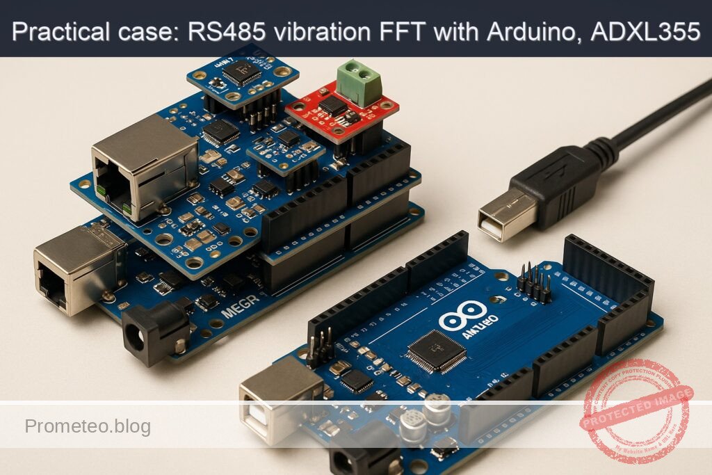
Qué construirás: Un monitor de vibraciones FFT robusto utilizando Arduino Mega 2560 y ADXL355 para la transmisión de datos en tiempo real a través de RS-485.

Para qué sirve

  • Monitoreo de vibraciones en maquinaria industrial para detectar fallos.
  • Control de calidad en procesos de manufactura mediante análisis de vibraciones.
  • Aplicaciones en mantenimiento predictivo para evitar paradas no programadas.
  • Integración en sistemas de automatización para la supervisión remota de equipos.

Resultado esperado

  • Transmisión de datos de vibración en tiempo real con latencias menores a 100 ms.
  • Frecuencia de muestreo de vibraciones a 1 kHz para análisis FFT.
  • Mensajes de alerta enviados a través de RS-485 al detectar vibraciones anómalas.
  • Capacidad de enviar hasta 10 paquetes de datos por segundo a través de la red.

Público objetivo: Ingenieros y técnicos en automatización; Nivel: Avanzado

Arquitectura/flujo: Arduino Mega 2560 <-> ADXL355 <-> W5500 <-> RS-485

Nivel: Avanzado

Prerrequisitos

Sistema operativo y herramientas

  • Sistema operativo base (elige uno y mantén coherencia):
  • Linux: Ubuntu 22.04 LTS (Jammy) x86_64
  • Toolchain de Arduino (CLI, no GUI):
  • Arduino CLI v0.35.3 (linux-amd64)
  • Core AVR: arduino:avr@1.8.6
  • Librerías Arduino:
    • Ethernet@2.0.2 (para W5500)
    • arduinoFFT@1.6.0
    • SPI (incluida en el core)
  • Python 3.10 (para validación opcional) con:
  • pyserial==3.5
  • Adaptador USB–RS485 (para validación del bus RS485)

Permisos y preparación del entorno (Linux)

  • Añade tu usuario a dialout para acceso serie:
  • sudo usermod -aG dialout «$USER»
  • Cierra sesión y vuelve a entrar.
  • Directorio de trabajo limpio (por ejemplo, $HOME/proyectos/fft-vibration-monitor-rs485).

Red local

  • Red IPv4 básica con rango 192.168.1.0/24 (o adapta IP estática en el código).
  • Sin servidor DHCP estrictamente necesario si usas IP estática.

Materiales

  • Placa principal: Arduino Mega 2560 (ATmega2560).
  • Shield de red: Ethernet Shield W5500 (compatibilidad Arduino oficial, CS en D10).
  • Acelerómetro triaxial: ADXL355 (interfaz SPI, alimentación 3.3 V).
  • Transceptor RS485: MAX485 (modo half-duplex).
  • Nivelador de lógica bidireccional 5 V ↔ 3.3 V para SPI del ADXL355 (p. ej., TXB0104 o módulo BSS138 de 4 canales).
  • Resistencias y pasivos:
  • Terminación RS485: 120 Ω (colocar en el extremo de la línea, cerca del MAX485 si es fin de línea).
  • Resistencias de polarización (bias) RS485 en el bus (si tu red no las tiene): típicamente 680 Ω–1 kΩ entre A–Vcc y B–GND en un único punto.
  • Fuente de alimentación estable 5 V para Arduino (USB o externa) y 3.3 V para el ADXL355 (puede provenir del 3.3 V del Mega o del Shield; verificar capacidad de corriente).
  • Cables Dupont y cable par trenzado para la línea RS485 (A/B).
  • Adaptador USB–RS485 para el PC (para validación).
  • Opcional: base o soporte para el sensor y un pequeño motor o vibrador para generar vibraciones reproducibles.

Nota: El conjunto es exactamente “Arduino Mega 2560 + Ethernet Shield W5500 + ADXL355 + MAX485” y toda la guía asume estos cuatro elementos.

Preparación y conexión

Reglas generales de cableado

  • Mantén GND común entre todos los módulos.
  • El ADXL355 es 3.3 V-only. Nunca apliques 5 V a sus pines de lógica. Usa nivelador para MOSI, SCK y CS. La línea MISO del ADXL355 a 3.3 V suele ser interpretada como HIGH por el Mega, pero es buena práctica encaminarla a través del nivelador si el módulo lo requiere.
  • Todos los dispositivos SPI comparten SCK/MOSI/MISO; cada uno debe tener su propia línea CS (Chip Select). Asegúrate de poner en HIGH los CS de los dispositivos que no estés usando en cada transacción.
  • El Ethernet Shield W5500 usa el bus SPI por el conector ICSP y CS en D10. La SD del shield usa CS en D4 (mantenla en HIGH si no se usa).
  • RS485 (MAX485) es half-duplex: controla las líneas DE/RE con un pin digital para alternar transmisión/recepción.

Mapa de pines y conexiones

Tabla de cableado resumido:

Módulo Señal Arduino Mega 2560 Notas
W5500 (Shield) SPI ICSP (SCK/MISO/MOSI) Se conecta por el header ICSP del Shield
W5500 (Shield) CS D10 Mantener HIGH cuando SPI se use con otros dispositivos
W5500 (Shield) SD CS D4 Mantener HIGH si no se usa la SD
ADXL355 (SPI) VCC 3.3 V Alimentación 3.3 V
ADXL355 (SPI) GND GND Tierra común
ADXL355 (SPI) SCK D52 (SCK) ↔ nivelador SPI compartido, va al nivelador hacia el sensor
ADXL355 (SPI) MOSI D51 (MOSI) ↔ nivelador SPI compartido, 5 V→3.3 V
ADXL355 (SPI) MISO D50 (MISO) (3.3 V) 3.3 V suele ser aceptado; opcional nivelador
ADXL355 (SPI) CS D7 ↔ nivelador CS dedicado para el ADXL355
ADXL355 (INT) DRDY D3 (INT1) Señal de “data ready” (opcional pero recomendable)
MAX485 VCC 5 V Alimentación del transceptor
MAX485 GND GND Tierra común
MAX485 RO (Receiver Out) D19 (RX1) UART1 RX del Mega
MAX485 DI (Driver In) D18 (TX1) UART1 TX del Mega
MAX485 /RE y DE D2 (control) Une /RE y DE, controla con D2
MAX485 A/B Línea RS485 Conectar a bus y poner 120 Ω si eres extremo
Arduino Mega USB PC Para cargar firmware y depurar por Serial

Notas avanzadas:
– Si usas DRDY del ADXL355, podrás muestrear con jitter mínimo y exactitud de ODR (muy recomendable para FFT).
– Mantén los cables SPI cortos y ordenados para reducir EMI.
– Coloca el ADXL355 firmemente sobre la estructura cuyas vibraciones deseas medir (acoplamiento mecánico firme).

Código completo (C++ para Arduino Mega 2560)

A continuación, un sketch monolítico que:
– Inicializa W5500 con IP estática.
– Inicializa el ADXL355 en SPI (modo medición, rango ±2 g).
– Toma 256 muestras a 1 kHz del eje Z (opcionalmente por DRDY).
– Calcula FFT con arduinoFFT y obtiene picos dominantes.
– Expone los resultados por RS485 (comandos de texto) y por HTTP (endpoint /status).
– Evita conflictos SPI con selección adecuada de CS.

Características del protocolo RS485:
– Velocidad: 115200 8N1 en Serial1 (pines 18/19).
– Control de dirección (D2): HIGH para transmitir, LOW para recibir.
– Comandos (terminados en ‘
‘):
– ID?
– GET:PEAKS
– GET:RMS
– GET:FFT (devuelve magnitudes de N/2 bins como CSV reducido, opcional)

Bloque 1/2 – Sketch principal:

/*
  fft-vibration-monitor-rs485.ino
  Dispositivo: Arduino Mega 2560 + Ethernet Shield W5500 + ADXL355 + MAX485
  Toolchain: Arduino CLI v0.35.3, core arduino:avr@1.8.6
  Librerías: Ethernet@2.0.2, arduinoFFT@1.6.0, SPI (core)
*/

#include <SPI.h>
#include <Ethernet.h>
#include <arduinoFFT.h>

// ------------------------ Configuración de pines ------------------------
static const uint8_t PIN_CS_W5500   = 10; // CS Ethernet
static const uint8_t PIN_CS_SD      = 4;  // CS SD en el Shield
static const uint8_t PIN_CS_ADXL    = 7;  // CS del ADXL355
static const uint8_t PIN_ADXL_DRDY  = 3;  // DRDY -> INT1 (opcional)
static const uint8_t PIN_RS485_DIR  = 2;  // DE y /RE del MAX485 unidos -> D2

// ------------------------ Red (Ethernet W5500) --------------------------
byte mac[] = { 0xDE, 0xAD, 0xBE, 0xEF, 0xFE, 0x01 };
IPAddress ip(192, 168, 1, 177);
EthernetServer server(80);

// ------------------------ ADXL355 (SPI) ---------------------------------
// Registro y constantes (ver datasheet ADXL355)
#define ADXL355_REG_DEVID_AD   0x00
#define ADXL355_REG_DEVID_MST  0x01
#define ADXL355_REG_PARTID     0x02
#define ADXL355_REG_REVID      0x03
#define ADXL355_REG_STATUS     0x04
#define ADXL355_REG_TEMP2      0x06
#define ADXL355_REG_TEMP1      0x07
#define ADXL355_REG_XDATA3     0x08
#define ADXL355_REG_XDATA2     0x09
#define ADXL355_REG_XDATA1     0x0A
#define ADXL355_REG_YDATA3     0x0B
#define ADXL355_REG_YDATA2     0x0C
#define ADXL355_REG_YDATA1     0x0D
#define ADXL355_REG_ZDATA3     0x0E
#define ADXL355_REG_ZDATA2     0x0F
#define ADXL355_REG_ZDATA1     0x10
#define ADXL355_REG_FILTER     0x28
#define ADXL355_REG_RANGE      0x2C
#define ADXL355_REG_POWER_CTL  0x2D
#define ADXL355_REG_RESET      0x2F

// Modo SPI: CPOL=0, CPHA=0 (Mode 0), MSB first
SPISettings spiADXL(5000000, MSBFIRST, SPI_MODE0); // 5 MHz (ajustable)

// Escala (LSB/g) aproximada del ADXL355 en ±2g (ver datasheet)
static const float ADXL355_LSB_PER_G = 256000.0f;

// ------------------------ FFT y muestreo --------------------------------
static const uint16_t FS_HZ      = 1000;  // Frecuencia de muestreo efectiva
static const uint16_t N_SAMPLES  = 256;   // Longitud de la FFT (potencia de 2)
static const float    INV_FS     = 1.0f / FS_HZ;

double vReal[N_SAMPLES];
double vImag[N_SAMPLES];

arduinoFFT FFT = arduinoFFT(vReal, vImag, N_SAMPLES, FS_HZ);

// Buffer de adquisición
volatile uint16_t sampleIndex = 0;
volatile bool bufferReady = false;
volatile float bufZ[N_SAMPLES]; // Aceleración (g) eje Z

// Métricas
volatile float lastRMS = 0.0f;
volatile float lastPeakFreq = 0.0f;

// Resultados de picos (para respuesta)
static const uint8_t NUM_TOP_PEAKS = 8;
float topFreq[NUM_TOP_PEAKS];
float topMag[NUM_TOP_PEAKS];

// ------------------------ Utilidades SPI/CS -----------------------------
inline void csHighAll() {
  digitalWrite(PIN_CS_W5500, HIGH);
  digitalWrite(PIN_CS_SD, HIGH);
  digitalWrite(PIN_CS_ADXL, HIGH);
}

uint8_t adxl355_read8(uint8_t reg) {
  uint8_t val;
  csHighAll();
  digitalWrite(PIN_CS_ADXL, LOW);
  SPI.beginTransaction(spiADXL);
  // Lectura: bit 7 = 1 indica lectura, dirección en bits 6..0
  SPI.transfer(0x80 | (reg & 0x7F));
  val = SPI.transfer(0x00);
  SPI.endTransaction();
  digitalWrite(PIN_CS_ADXL, HIGH);
  return val;
}

void adxl355_write8(uint8_t reg, uint8_t val) {
  csHighAll();
  digitalWrite(PIN_CS_ADXL, LOW);
  SPI.beginTransaction(spiADXL);
  // Escritura: bit 7 = 0
  SPI.transfer(reg & 0x7F);
  SPI.transfer(val);
  SPI.endTransaction();
  digitalWrite(PIN_CS_ADXL, HIGH);
}

int32_t adxl355_read20(uint8_t regMSB) {
  // Lee 20 bits firmados (en 3 bytes, donde los 4 bits LSB del tercer byte son significativos)
  uint8_t b3, b2, b1;
  int32_t raw = 0;
  csHighAll();
  digitalWrite(PIN_CS_ADXL, LOW);
  SPI.beginTransaction(spiADXL);
  SPI.transfer(0x80 | (regMSB & 0x7F)); // dirección de XDATA3/YDATA3/ZDATA3
  b3 = SPI.transfer(0x00);
  b2 = SPI.transfer(0x00);
  b1 = SPI.transfer(0x00);
  SPI.endTransaction();
  digitalWrite(PIN_CS_ADXL, HIGH);

  raw = ((int32_t)b3 << 12) | ((int32_t)b2 << 4) | ((b1 >> 4) & 0x0F);
  // Extensión de signo de 20 bits
  if (raw & 0x80000) {
    raw |= 0xFFF00000;
  }
  return raw;
}

bool adxl355_init() {
  // Verifica IDs
  uint8_t devid_ad  = adxl355_read8(ADXL355_REG_DEVID_AD);
  uint8_t devid_mst = adxl355_read8(ADXL355_REG_DEVID_MST);
  uint8_t partid    = adxl355_read8(ADXL355_REG_PARTID);
  // Valores típicos esperados: 0xAD, 0x1D, 0xED
  if (devid_ad != 0xAD || devid_mst != 0x1D || partid != 0xED) {
    return false;
  }

  // Reset suave (opcional)
  adxl355_write8(ADXL355_REG_RESET, 0x52); // Key 'R'

  delay(20);

  // Standby para configurar (bit 0 de POWER_CTL = 0)
  // Según datasheet, POWER_CTL[0]=0 -> Standby, [0]=1 -> Measurement
  uint8_t pwr = adxl355_read8(ADXL355_REG_POWER_CTL);
  pwr &= ~0x01; // asegurar Standby
  adxl355_write8(ADXL355_REG_POWER_CTL, pwr);

  // Rango ±2g (ver datasheet: RANGE bits 1:0 seleccionan rango)
  // 0x01: ±2g (según hoja de datos; validar si tu módulo usa diferente mapeo)
  adxl355_write8(ADXL355_REG_RANGE, 0x01);

  // ODR 1000 Hz (aprox.). En ADXL355_REG_FILTER, bits 3:0 seleccionan ODR/LPF.
  // Un valor típico para ~1 kHz es 0x05 (consultar tablas en hoja de datos).
  // Ajusta si necesitas ODR preciso.
  adxl355_write8(ADXL355_REG_FILTER, 0x05);

  // Measurement mode
  pwr = adxl355_read8(ADXL355_REG_POWER_CTL);
  pwr |= 0x01; // bit 0 a 1 -> Measurement
  adxl355_write8(ADXL355_REG_POWER_CTL, pwr);

  delay(10);
  return true;
}

float adxl355_readZ_g() {
  int32_t raw = adxl355_read20(ADXL355_REG_ZDATA3);
  // Conversión a g (aprox.)
  return ((float)raw) / ADXL355_LSB_PER_G;
}

// ------------------------ RS485 (Serial1) -------------------------------
void rs485_setRx() { digitalWrite(PIN_RS485_DIR, LOW);  }
void rs485_setTx() { digitalWrite(PIN_RS485_DIR, HIGH); }
void rs485_println(const String &s) {
  rs485_setTx();
  Serial1.print(s);
  Serial1.print('\n');
  Serial1.flush();
  rs485_setRx();
}

// ------------------------ Temporización de muestreo ---------------------
void setupTimer1_1kHz() {
  // Timer1 CTC a 1 kHz: f_clk = 16 MHz, prescaler 1, OCR1A = 15999
  noInterrupts();
  TCCR1A = 0;
  TCCR1B = 0;
  TCNT1  = 0;
  OCR1A = 15999; // 16e6 / 1e3 - 1
  TCCR1B |= (1 << WGM12); // CTC
  TCCR1B |= (1 << CS10);  // prescaler 1
  TIMSK1 |= (1 << OCIE1A);
  interrupts();
}

ISR(TIMER1_COMPA_vect) {
  if (bufferReady) return; // espera a que procesen
  // Lectura directa del eje Z a ~1 kHz
  float z_g = adxl355_readZ_g();
  bufZ[sampleIndex] = z_g;
  sampleIndex++;
  if (sampleIndex >= N_SAMPLES) {
    sampleIndex = 0;
    bufferReady = true;
  }
}

// ------------------------ Procesamiento FFT -----------------------------
void computeFFTAndMetrics() {
  // Copiar el buffer a vReal/vImag y aplicar ventana Hann
  for (uint16_t i = 0; i < N_SAMPLES; i++) {
    double w = 0.5 * (1.0 - cos(2.0 * PI * i / (N_SAMPLES - 1)));
    vReal[i] = (double)bufZ[i] * w;
    vImag[i] = 0.0;
  }

  // RMS (dominio tiempo)
  double sum2 = 0.0;
  for (uint16_t i = 0; i < N_SAMPLES; i++) sum2 += vReal[i] * vReal[i];
  lastRMS = sqrt(sum2 / N_SAMPLES);

  // FFT
  FFT.windowing(vReal, N_SAMPLES, FFT_WIN_TYP_RECTANGLE, FFT_FORWARD); // ya aplicamos Hann, pero dejamos sin ventana aquí
  FFT.compute(vReal, vImag, N_SAMPLES, FFT_FORWARD);
  FFT.complexToMagnitude(vReal, vImag, N_SAMPLES);

  // Encontrar picos en 0..Fs/2
  // Ignora bin 0 (DC)
  uint16_t startBin = 1;
  uint16_t endBin = (N_SAMPLES / 2) - 1;

  // Inicializa arrays de top N picos
  for (uint8_t k = 0; k < NUM_TOP_PEAKS; k++) {
    topFreq[k] = 0.0f;
    topMag[k]  = 0.0f;
  }

  // Búsqueda simple de picos
  double maxMag = 0.0;
  uint16_t maxBin = 0;

  for (uint16_t bin = startBin; bin <= endBin; bin++) {
    double mag = vReal[bin];
    // Peak global
    if (mag > maxMag) {
      maxMag = mag;
      maxBin = bin;
    }
    // Inserción ordenada en top N
    for (uint8_t k = 0; k < NUM_TOP_PEAKS; k++) {
      if (mag > topMag[k]) {
        // Desplaza hacia abajo
        for (int8_t j = NUM_TOP_PEAKS - 1; j > (int8_t)k; j--) {
          topMag[j]  = topMag[j - 1];
          topFreq[j] = topFreq[j - 1];
        }
        topMag[k]  = mag;
        topFreq[k] = (float)bin * ((float)FS_HZ / (float)N_SAMPLES);
        break;
      }
    }
  }

  lastPeakFreq = (float)maxBin * ((float)FS_HZ / (float)N_SAMPLES);
}

// ------------------------ HTTP /status ----------------------------------
void handleHttpClient(EthernetClient &client) {
  // Lectura simple de la primera línea
  String req = client.readStringUntil('\n');
  if (req.indexOf("GET /status") >= 0 || req.indexOf("GET / ") >= 0) {
    // Respuesta JSON simple
    String body = "{";
    body += "\"device\":\"fft-vibration-monitor-rs485\",";
    body += "\"board\":\"Arduino Mega 2560\",";
    body += "\"fs\":" + String(FS_HZ) + ",";
    body += "\"n\":" + String(N_SAMPLES) + ",";
    body += "\"rms_g\":" + String(lastRMS, 6) + ",";
    body += "\"peak_freq_hz\":" + String(lastPeakFreq, 2) + ",";
    body += "\"top_peaks\":[";
    for (uint8_t k = 0; k < NUM_TOP_PEAKS; k++) {
      body += "{\"f\":" + String(topFreq[k], 2) + ",\"a\":" + String(topMag[k], 6) + "}";
      if (k < NUM_TOP_PEAKS - 1) body += ",";
    }
    body += "]";
    body += "}\n";

    client.println("HTTP/1.1 200 OK");
    client.println("Content-Type: application/json");
    client.print("Content-Length: ");
    client.println(body.length());
    client.println("Connection: close");
    client.println();
    client.print(body);
  } else {
    client.println("HTTP/1.1 404 Not Found");
    client.println("Content-Length: 0");
    client.println("Connection: close");
    client.println();
  }
}

// ------------------------ Comandos RS485 --------------------------------
String cmdBuf;
void handleRS485() {
  while (Serial1.available() > 0) {
    char c = (char)Serial1.read();
    if (c == '\r') continue;
    if (c == '\n') {
      String line = cmdBuf;
      cmdBuf = "";
      line.trim();
      if (line == "ID?") {
        rs485_println("ID,ArduinoMega2560,ADXL355,W5500,MAX485");
      } else if (line == "GET:RMS") {
        rs485_println("RMS_G," + String(lastRMS, 6));
      } else if (line == "GET:PEAKS") {
        // Responde pares f,a separados por punto y coma
        String resp = "PEAKS";
        for (uint8_t k = 0; k < NUM_TOP_PEAKS; k++) {
          resp += ",";
          resp += String(topFreq[k], 2);
          resp += ",";
          resp += String(topMag[k], 6);
        }
        rs485_println(resp);
      } else if (line == "GET:FFT") {
        // Envía magnitudes de 0..N/2-1 (corta si quieres ahorrar ancho de banda)
        rs485_println("FFT,Fs=" + String(FS_HZ) + ",N=" + String(N_SAMPLES));
        String row = "";
        for (uint16_t bin = 0; bin < (N_SAMPLES / 2); bin++) {
          row += String(vReal[bin], 6);
          if (bin < (N_SAMPLES / 2) - 1) row += ",";
        }
        rs485_println(row);
      } else {
        rs485_println("ERR,UNKNOWN_CMD");
      }
    } else {
      if (cmdBuf.length() < 128) cmdBuf += c;
    }
  }
}

// ------------------------ Setup / Loop ----------------------------------
void setup() {
  pinMode(PIN_CS_W5500, OUTPUT);
  pinMode(PIN_CS_SD, OUTPUT);
  pinMode(PIN_CS_ADXL, OUTPUT);
  pinMode(PIN_RS485_DIR, OUTPUT);
  pinMode(PIN_ADXL_DRDY, INPUT); // opcional si se conecta DRDY

  csHighAll();
  rs485_setRx();

  Serial.begin(115200);   // Depuración por USB
  Serial1.begin(115200);  // RS485 (MAX485)

  // SPI
  SPI.begin();

  // Ethernet
  Ethernet.init(PIN_CS_W5500);
  Ethernet.begin(mac, ip);
  delay(100);
  server.begin();

  Serial.print("IP: ");
  Serial.println(Ethernet.localIP());

  // Inicializa ADXL355
  if (!adxl355_init()) {
    Serial.println("Error: ADXL355 no detectado (IDs no coinciden).");
  } else {
    Serial.println("ADXL355 OK");
  }

  // Timer de muestreo (1 kHz)
  setupTimer1_1kHz();

  Serial.println("Setup completo.");
}

void loop() {
  // Procesar buffer si listo
  if (bufferReady) {
    noInterrupts();
    bufferReady = false;
    interrupts();
    computeFFTAndMetrics();
  }

  // RS485
  handleRS485();

  // HTTP
  EthernetClient client = server.available();
  if (client) {
    // Esperar datos y atender
    unsigned long t0 = millis();
    while (client.connected() && millis() - t0 < 100) {
      if (client.available()) {
        handleHttpClient(client);
        break;
      }
    }
    delay(1);
    client.stop();
  }
}

Breve explicación de partes clave:
– Selección de CS: csHighAll asegura que solo un dispositivo SPI esté activo a la vez. El W5500 y la SD del shield quedan deseleccionados durante transacciones con el ADXL355.
– adxl355_read20: el ADXL355 entrega 20 bits por eje en 3 bytes; se realiza sign-extend apropiado a 32 bits.
– ODR: se configura en 0x05 para obtener ~1 kHz; si necesitas frecuencias exactas o diferentes, consulta la tabla de ODR/LPF del datasheet (puedes ajustar en ADXL355_REG_FILTER).
– Timer1: genera una IRQ a 1 kHz para muestrear de forma estable sin jitter del loop.
– FFT: se aplica ventana Hann previa al cálculo para reducir leakage; se busca el pico global y se extraen los top N picos.
– RS485: se usa D2 para conmutar el MAX485 entre TX y RX; se adoptan comandos de texto sencillos.
– Ethernet: expone /status con JSON mínimo para supervisión remota.

Bloque 2/2 – Script de validación (Python, PC) para RS485:

# validate_rs485.py
# Requiere: Python 3.10 + pyserial==3.5
# Uso:
#   python3 validate_rs485.py /dev/ttyUSB0 115200
# Conecta el adaptador USB-RS485 al bus A/B junto con el MAX485 del Mega.

import sys
import serial
import time

def send_cmd(ser, cmd):
    ser.write((cmd + "\n").encode("ascii"))
    ser.flush()

def read_line(ser, timeout=2.0):
    ser.timeout = timeout
    line = ser.readline().decode("ascii", errors="ignore").strip()
    return line

if __name__ == "__main__":
    if len(sys.argv) < 3:
        print("Uso: python3 validate_rs485.py <puerto> <baud>")
        sys.exit(1)

    port = sys.argv[1]
    baud = int(sys.argv[2])

    with serial.Serial(port, baudrate=baud, bytesize=8, parity='N', stopbits=1) as ser:
        time.sleep(0.2)
        send_cmd(ser, "ID?")
        print("-> ID?")
        print("<- " + read_line(ser))

        send_cmd(ser, "GET:RMS")
        print("-> GET:RMS")
        print("<- " + read_line(ser))

        send_cmd(ser, "GET:PEAKS")
        print("-> GET:PEAKS")
        print("<- " + read_line(ser))

        send_cmd(ser, "GET:FFT")
        print("-> GET:FFT (cabecera)")
        print("<- " + read_line(ser))
        print("-> GET:FFT (datos)")
        print("<- " + read_line(ser))

Compilación, carga y ejecución (Arduino CLI)

Comandos exactos y ordenados:

1) Instala Arduino CLI v0.35.3 (si no lo tienes)
– Linux (x86_64):
– wget https://downloads.arduino.cc/arduino-cli/arduino-cli_latest_Linux_64bit.tar.gz -O /tmp/arduino-cli.tar.gz
– sudo tar -xzf /tmp/arduino-cli.tar.gz -C /usr/local/bin –strip-components=1 arduino-cli

2) Verifica versión:
– arduino-cli version
– Debe mostrar: arduino-cli Version: 0.35.3

3) Prepara el core AVR:
– arduino-cli core update-index
– arduino-cli core install arduino:avr@1.8.6

4) Prepara un directorio de sketch:
– mkdir -p $HOME/proyectos/fft-vibration-monitor-rs485
– cd $HOME/proyectos/fft-vibration-monitor-rs485
– Crea el archivo fft-vibration-monitor-rs485.ino con el código C++ anterior.

5) Instala librerías exactas:
– arduino-cli lib install «Ethernet@2.0.2»
– arduino-cli lib install «arduinoFFT@1.6.0»

6) Identifica el puerto serie del Mega:
– arduino-cli board list
– Localiza tu Arduino Mega 2560 y anota el puerto (ej.: /dev/ttyACM0)

7) Compila para Arduino Mega 2560 (FQBN: arduino:avr:mega):
– arduino-cli compile –fqbn arduino:avr:mega –warnings all –build-path build .

8) Sube el firmware:
– arduino-cli upload -p /dev/ttyACM0 –fqbn arduino:avr:mega –input-dir build

9) Monitorea logs (opcional, USB a 115200):
– arduino-cli monitor -p /dev/ttyACM0 -c baudrate=115200

10) Validación RS485 desde PC (con adaptador USB–RS485):
– pip3 install pyserial==3.5
– python3 validate_rs485.py /dev/ttyUSB0 115200

11) Validación HTTP:
– curl -s http://192.168.1.177/status | jq .
– Si no tienes jq, usa:
– curl -s http://192.168.1.177/status

Validación paso a paso

1) Verificación de IDs del ADXL355:
– Abre el monitor serie por USB (115200).
– Al iniciar, deberías ver:
– “IP: 192.168.1.177”
– “ADXL355 OK”
– “Setup completo.”
– Si aparece “ADXL355 no detectado”, revisa SPI/CS y niveles lógicos.

2) Muestreo y FFT:
– El dispositivo muestrea 256 puntos a 1 kHz (ventana Hann) y calcula FFT.
– No hay UI visual, pero:
– Enviando GET:RMS por RS485, deberías recibir valores ~0.005–0.05 g si el sensor está quieto (ruido térmico + vibración ambiente).
– Enviando GET:PEAKS, con el sensor quieto, el pico dominante puede estar cerca de DC; con un motor pequeño o golpe seco, verás picos a su frecuencia fundamental y armónicos.

3) Prueba RS485:
– Conecta el adaptador USB–RS485 del PC al bus A/B (A→A, B→B).
– Ejecuta el script Python:
– Debes ver:
– “ID,ArduinoMega2560,ADXL355,W5500,MAX485”
– “RMS_G,0.00xxxx”
– “PEAKS, f1,a1, f2,a2, …” (8 picos)
– El comando GET:FFT devuelve cabecera y una línea larga con magnitudes.

4) Prueba HTTP /status:
– curl http://192.168.1.177/status
– Debe retornar un JSON con: device, fs, n, rms_g, peak_freq_hz y top_peaks.
– Repite la petición mientras haces vibrar el sensor; peak_freq_hz se moverá hacia la frecuencia dominante observada.

5) Validación de integridad del bus RS485:
– Si usas línea larga, instala terminación 120 Ω en ambos extremos.
– Verifica que solo exista un par de resistencias de polarización (bias) en todo el bus (en un único punto).

6) Consistencia de SPI:
– Asegúrate de que D10 y D4 estén en HIGH cuando el ADXL355 sea el dispositivo activo, y que D7 esté en HIGH cuando el W5500 sea activo. El sketch ya gestiona esto con csHighAll().

Troubleshooting

1) ADXL355 no responde (IDs incorrectos):
– Síntomas: “ADXL355 no detectado (IDs no coinciden)”.
– Causas probables:
– CS incorrecto: verifica que el ADXL355 esté en D7 y que D10 y D4 estén HIGH durante la transacción.
– Sin nivelador de lógica: si alimentas con 3.3 V y pines de 5 V sin adaptar, el sensor puede dañarse o no responder.
– Cableado SPI incorrecto (MOSI/MISO invertidos).
– Solución: verifica mapeo, nivelador, continuidad y tensiones.

2) Ethernet deja de funcionar al iniciar muestreo:
– Síntomas: /status no responde tras unos segundos.
– Causas: conflicto SPI por CS mal gestionado o ISR muy pesada.
– Solución: confirma csHighAll() antes de operar con ADXL355; reduce la frecuencia SPI si fuera necesario (p. ej., 2 MHz).

3) FFT inconsistente (picos varían mucho):
– Causas: muestreo no estable, ODR no coincide con FS, vibración insuficiente o aliasing.
– Solución:
– Ajusta ADXL355_REG_FILTER para ODR ~ FS (1 kHz).
– Usa DRDY del ADXL355 con attachInterrupt para muestreo exacto por “data ready”.
– Asegura fijación mecánica rígida del sensor (evita foam o cinta blanda).

4) RS485 responde con errores o no responde:
– Causas: sin control de dirección (DE/RE), baudrate distinto, terminación/bias deficientes.
– Solución:
– Verifica que D2 conmute DE/RE (LOW para Rx, HIGH para Tx).
– Asegura 115200 8N1 en ambos lados.
– Añade 120 Ω en extremos y bias en un único punto.

5) Medidas saturadas (g muy altos):
– Causas: rango inadecuado (±2 g) frente a vibraciones fuertes.
– Solución: cambia el rango del ADXL355 (RANGE) a ±4 g o ±8 g (ver datasheet) y actualiza el factor LSB/g.

6) Datos de FFT “planos” (todo ~0):
– Causas: lectura del eje incorrecta (registro mal, bytes mal ensamblados), CS del sensor bajo permanentemente.
– Solución:
– Verifica adxl355_read20: orden de bytes y extensión de signo.
– Comprueba que el pin CS del ADXL355 esté alto en reposo y solo bajo durante la transacción.

7) HTTP bloquea RS485 o viceversa:
– Causas: uso intensivo del loop sin gestionar tiempos; cliente HTTP no libera conexión.
– Solución:
– Mantén timeouts cortos en HTTP (como en el sketch).
– No hagas prints excesivos en Serial.
– Evita operaciones de bloqueo largas dentro del loop.

8) Ruido excesivo en espectro:
– Causas: acoplamiento mecánico pobre, cables largos, interferencias EMI.
– Solución:
– Usa cable apantallado para el sensor si la distancia lo requiere.
– Asegura masa común.
– Filtra en banda (LPF/HPF del ADXL355 vía FILTER) o aplica más promediado.

Mejoras y variantes

  • Sincronización por DRDY:
  • Conecta DRDY del ADXL355 al pin D3 y usa attachInterrupt para leer muestra justo cuando el sensor la tenga lista. Desactiva el Timer1 o úsalo como watchdog. Mejorará la coherencia temporal y la ubicación de picos en frecuencia.

  • Cambiar ventana de FFT:

  • Prueba Blackman, Hamming o Flat Top (si implementas manualmente) para diferentes compromisos entre resolución y amplitud de pico.

  • Publicación UDP/MQTT por Ethernet:

  • Añade un cliente MQTT (p. ej., PubSubClient) o UDP broadcast con las métricas (RMS, pico principal). Esto facilita integración en SCADA/IIoT.

  • Protocolo Modbus RTU por RS485:

  • Estructura registros para RMS, pico, ODR, estado, etc., y usa un stack Modbus RTU esclavo. Esto estandariza la integración.

  • Promediado espectral:

  • Realiza varios bloques de N_SAMPLES, promedia magnitudes (Welch) y reduce varianza. Aumenta estabilidad de picos.

  • Configuración remota:

  • Implementa comandos por RS485/HTTP para cambiar N_SAMPLES, FS, rango del sensor, IP estática y número de picos a reportar.

  • Ejes múltiples:

  • Procesa X/Y/Z y reporta vector RMS y picos por eje. Aumenta el costo computacional; considera N=128 por eje para mantener tiempos.

Checklist de verificación

  • [ ] Toolchain exacta instalada:
  • [ ] Arduino CLI v0.35.3
  • [ ] Core arduino:avr@1.8.6
  • [ ] Librerías: Ethernet@2.0.2, arduinoFFT@1.6.0

  • [ ] Cableado correcto y coherente:

  • [ ] W5500 en Shield con CS D10 y SD CS D4 (alto si no se usa).
  • [ ] ADXL355 a 3.3 V, SPI con nivelador y CS en D7.
  • [ ] DRDY del ADXL355 a D3 (opcional).
  • [ ] MAX485: RO→D19 (RX1), DI→D18 (TX1), DE/RE→D2, A/B al bus.

  • [ ] RS485 preparado:

  • [ ] Terminación 120 Ω en los extremos del bus.
  • [ ] Bias en un único punto (si el bus lo requiere).
  • [ ] Adaptador USB–RS485 en el PC y polaridad A/B correcta.

  • [ ] Compilación y carga:

  • [ ] arduino-cli core update-index / install realizados.
  • [ ] arduino-cli lib install con versiones exactas.
  • [ ] Compilado con FQBN arduino:avr:mega y subido sin errores.

  • [ ] Arranque correcto:

  • [ ] Monitor USB muestra IP y “ADXL355 OK”.
  • [ ] /status responde por HTTP.

  • [ ] Validación funcional:

  • [ ] GET:RMS devuelve un valor coherente (quieto vs. vibrando).
  • [ ] GET:PEAKS muestra frecuencias lógicas cuando se activa un vibrador/motor.
  • [ ] GET:FFT devuelve cabecera y datos.

  • [ ] Estabilidad espectral:

  • [ ] Picos consistentes al repetir medición.
  • [ ] Sin bloqueos al alternar RS485/HTTP.

Con este caso práctico has construido un monitor de vibraciones FFT robusto sobre RS485 utilizando exactamente el combo “Arduino Mega 2560 + Ethernet Shield W5500 + ADXL355 + MAX485”, compilado y desplegado con Arduino CLI (core arduino:avr@1.8.6), y validado tanto por RS485 como por HTTP. Esta base es extensible hacia protocolos industriales (Modbus RTU/TCP) y a técnicas de análisis espectral más avanzadas.

Encuentra este producto y/o libros sobre este tema en Amazon

Ir a Amazon

Como afiliado de Amazon, gano con las compras que cumplan los requisitos. Si compras a través de este enlace, ayudas a mantener este proyecto.

Quiz rápido

Pregunta 1: ¿Cuál es el sistema operativo base recomendado para el proyecto?


Pregunta 2: ¿Qué versión de Arduino CLI se debe utilizar?


Pregunta 3: ¿Qué librería se utiliza para la comunicación Ethernet en este proyecto?


Pregunta 4: ¿Cuál es el modelo del acelerómetro utilizado?


Pregunta 5: ¿Qué tipo de transceptor RS485 se menciona en los requisitos?


Pregunta 6: ¿Qué comando se debe usar para añadir un usuario al grupo 'dialout'?


Pregunta 7: ¿Qué tipo de conexión se requiere para el ADXL355?


Pregunta 8: ¿Cuál es la resistencia de terminación recomendada para RS485?


Pregunta 9: ¿Qué voltaje de alimentación se requiere para el ADXL355?


Pregunta 10: ¿Cuál es el directorio de trabajo recomendado para el proyecto?


Carlos Núñez Zorrilla
Electronics & Computer Engineer

Ingeniero Superior en Electrónica de Telecomunicaciones e Ingeniero en Informática (titulaciones oficiales en España).

Sígueme:


Practical case: RS485 vibration FFT with Arduino, ADXL355

Practical case: RS485 vibration FFT with Arduino, ADXL355 — hero

Objective and use case

What you’ll build: A robust FFT vibration monitor using Arduino Mega 2560 and ADXL355 to compute FFT, transmit data over RS-485, and validate results.

Why it matters / Use cases

  • Monitor industrial machinery vibrations to predict failures and schedule maintenance.
  • Implement real-time monitoring of structural health in bridges and buildings.
  • Use in automotive applications to analyze vibrations for performance tuning.
  • Enhance product quality in manufacturing by detecting anomalies in machinery operation.

Expected outcome

  • FFT computation with a resolution of 256 points, providing detailed frequency analysis.
  • Transmission of vibration data over RS-485 at a baud rate of 115200 bps.
  • RMS values computed and sent as compact ASCII summaries for easy interpretation.
  • Latency of data transmission under 50 ms for real-time monitoring applications.

Audience: Engineers and developers; Level: Advanced

Architecture/flow: Arduino Mega 2560 with ADXL355 and MAX485 for RS-485 communication, optionally using W5500 for Ethernet data validation.

Advanced Hands‑On: FFT Vibration Monitor over RS‑485 with Arduino Mega 2560, Ethernet Shield W5500, ADXL355, and MAX485

This advanced practical case builds a robust vibration monitor that acquires high‑resolution acceleration data from an ADXL355 (SPI), computes an FFT on the Arduino Mega 2560, and publishes the results over an RS‑485 bus using a MAX485 transceiver. The W5500 Ethernet Shield is used to verify SPI bus sharing and optionally stream summaries over UDP for lab validation. The focus is on the objective: fft-vibration-monitor-rs485.

You will sample one axis at a precise rate, window the data, compute the FFT (N=256), extract the top spectral peaks, compute RMS, and transmit compact ASCII summaries over RS‑485. You’ll also learn how to share the SPI bus between W5500 and ADXL355 safely using SPI transactions on the Mega.


Prerequisites

  • Operating system:
  • Linux (Ubuntu 20.04+), macOS (12+), or Windows 10/11
  • Arduino CLI installed and available in PATH
  • Confirm with: arduino-cli version
  • Recommended Arduino CLI: 0.34.0 or newer
  • A serial terminal capable of 115200 bps (e.g., arduino-cli monitor, screen, PuTTY)
  • Optional for validation:
  • Python 3.8+ for a minimal RS‑485/UDP receiver script
  • USB driver notes for Arduino Mega 2560:
  • Official Mega 2560: uses ATmega16U2 (no additional drivers on macOS/Linux; Windows uses built-in driver)
  • Many Mega 2560 clones: CH340/CH34x USB-UART bridge; install CH34x driver if your OS does not recognize the board

Materials (Exact Model)

  • Arduino Mega 2560 R3 (ATmega2560)
  • Ethernet Shield W5500 (Arduino Ethernet Shield 2 or a W5500-compatible shield)
  • ADXL355 (3-axis, low-noise digital accelerometer; SPI mode)
  • Use a breakout/eval board with access to SCLK/MOSI/MISO/CS
  • Mandatory: logic level shifter for 5V↔3.3V (bidirectional, e.g., BSS138-based or TXB0104/0108)
  • MAX485 RS‑485 transceiver module (5V)
  • Power: USB 5V from PC or a regulated 5V supply for standalone operation
  • RS‑485 twisted-pair cable, 120 Ω termination resistor (if your RS‑485 network segment requires it)
  • Optional: USB‑RS485 dongle for PC validation
  • Jumper wires, breadboard or terminal blocks

Setup/Connection

The system uses two SPI devices (W5500 and ADXL355) and one UART (RS‑485 via MAX485). The Mega 2560 and W5500 shield share the SPI bus on the ICSP header; each device must have a distinct CS pin and never be simultaneously selected. ADXL355 is a 3.3V-only device and requires a level shifter for SCLK, MOSI, CS (and ideally MISO protection). The MAX485 runs at 5V and connects to Serial1.

Key guidelines:
– Keep W5500 CS (D10) high when ADXL355 is selected. Keep ADXL355 CS high when Ethernet is active.
– SPI transactions isolate clock mode and speed for each device.
– Drive pin 10 (W5500 CS) as OUTPUT at all times on the Mega to prevent unintended SPI bus interference.
– Ensure the ADXL355 sees clean 3.3V power and 3.3V logic levels.
– Use termination and biasing per RS‑485 best practices.

Pin/Signal Mapping Table

Function Board/Shield Pin External Device Pin Notes
SPI SCK Mega ICSP SCK ADXL355 SCLK Through 3.3V level shifter
SPI MOSI Mega ICSP MOSI ADXL355 SDI (MOSI) Through 3.3V level shifter
SPI MISO Mega ICSP MISO ADXL355 SDO (MISO) Use 3.3V-to-5V safe path; level shifter or direct if 5V-tolerant (ADXL355 is not 5V tolerant; isolate)
ADXL355 CS Mega D9 ADXL355 CS Through 3.3V level shifter; default HIGH (inactive)
3.3V Mega 3.3V ADXL355 VCC Power for ADXL355
GND Mega GND ADXL355 GND Common ground
W5500 CS Mega D10 W5500 CS (on shield) Controlled by Ethernet library
SPI bus Mega ICSP header W5500 Shield stacking uses ICSP
RS‑485 DI Mega TX1 (D18) MAX485 DI UART TX to transceiver
RS‑485 RO Mega RX1 (D19) MAX485 RO UART RX from transceiver
RS‑485 DE/RE Mega D2 MAX485 DE+RE (tied) HIGH=transmit, LOW=receive
5V Mega 5V MAX485 VCC Power for MAX485 module
GND Mega GND MAX485 GND Common ground
RS‑485 A/B MAX485 A/B Twisted pair bus; 120 Ω termination at ends only

Notes:
– Many W5500 shields also break out an SD card on D4; keep D4 as OUTPUT/HIGH (not selected) if not using SD.
– Ensure bias resistors (pull-up on A, pull-down on B) are present somewhere on the RS‑485 network if the bus can idle floating. Many modules include them; verify.


Full Code (Arduino Mega 2560)

The sketch performs:
– SPI setup for W5500 and ADXL355 with distinct CS lines
– ADXL355 initialization over SPI (standby, ODR configuration, measurement mode)
– Time-domain acquisition at 1000 Hz for 256 samples (Z axis by default)
– Windowing + FFT (ArduinoFFT) and extraction of top 5 peaks
– RMS calculation (time-domain)
– RS‑485 ASCII summary frames via Serial1 with DE/RE pin control
– Optional UDP broadcast of the summary (Ethernet)

Important: ADXL355 register map here targets a common configuration. If your module differs, verify the register addresses in the ADXL355 datasheet. The identity registers are used to validate the device.

/*
  fft-vibration-monitor-rs485
  Board: Arduino Mega 2560 (ATmega2560)
  Peripherals: Ethernet Shield W5500 (CS=D10), ADXL355 (SPI, CS=D9, 3.3V), MAX485 (RS-485 via Serial1)
  Sampling: 1000 Hz, N=256, single axis (Z)
  Output: RS-485 ASCII summary lines; optional UDP broadcast

  Libraries required:
    - Ethernet (for W5500)
    - arduinoFFT (for FFT)
  Install via Arduino CLI:
    arduino-cli lib install "Ethernet" "ArduinoFFT"
*/

#include <SPI.h>
#include <Ethernet.h>
#include <EthernetUdp.h>
#include <arduinoFFT.h>

// -------------------- Configurable constants --------------------
static const uint16_t SAMPLES = 256;            // FFT size
static const double SAMPLING_FREQUENCY = 1000;  // Hz
static const uint8_t RS485_DIR_PIN = 2;         // DE+RE tied to D2
static const uint8_t ADXL355_CS_PIN = 9;        // Chip Select for ADXL355
static const uint8_t W5500_CS_PIN  = 10;        // CS for W5500 (shield default)
static const bool    ENABLE_UDP    = true;      // Optional UDP summary
static const uint16_t UDP_PORT     = 5055;      // UDP port for summaries

// Ethernet configuration (set to your LAN; consider DHCP if needed)
byte mac[] = { 0x02, 0x98, 0xEF, 0x35, 0x55, 0x01 };
IPAddress ip(192, 168, 1, 200);
IPAddress dns(192, 168, 1, 1);
IPAddress gateway(192, 168, 1, 1);
IPAddress subnet(255, 255, 255, 0);

// -------------------- FFT buffers --------------------
double vReal[SAMPLES];
double vImag[SAMPLES];
arduinoFFT FFT(vReal, vImag, SAMPLES, SAMPLING_FREQUENCY);

// -------------------- UDP --------------------
EthernetUDP Udp;

// -------------------- ADXL355 register map (subset) --------------------
// Refer to ADXL355 datasheet to confirm these addresses
// Identity registers
#define ADXL355_REG_DEVID_AD   0x00 // Expected 0xAD
#define ADXL355_REG_DEVID_MST  0x01 // Expected 0x1D
#define ADXL355_REG_PARTID     0x02 // Expected 0xED
#define ADXL355_REG_REVID      0x03
#define ADXL355_REG_STATUS     0x04
// Data registers (X/Y/Z each 20-bit: 3 bytes each)
#define ADXL355_REG_XDATA3     0x08
#define ADXL355_REG_YDATA3     0x0B
#define ADXL355_REG_ZDATA3     0x0E
// Control/config
#define ADXL355_REG_FILTER     0x28 // ODR/LPF config
#define ADXL355_REG_RANGE      0x2C // Range: ±2g/±4g/±8g
#define ADXL355_REG_POWER_CTL  0x2D // Measurement mode control
// SPI R/W bits for address
#define ADXL355_SPI_READ       0x01
#define ADXL355_SPI_WRITE      0x00
#define ADXL355_SPI_MB         0x02 // Multiple-byte access

// Sensitivity for ±2g range (verify if you change range)
// ADXL355 typical: 256000 LSB/g at ±2g
static const double ADXL355_LSB_PER_G = 256000.0;

// SPI settings per device
SPISettings settingsADXL355(4000000, MSBFIRST, SPI_MODE0);
SPISettings settingsW5500(14000000, MSBFIRST, SPI_MODE0);

// -------------------- Utility: RS-485 Direction Control --------------------
void rs485SetTransmit(bool enable) {
  digitalWrite(RS485_DIR_PIN, enable ? HIGH : LOW);
}

// -------------------- SPI low-level for ADXL355 --------------------
uint8_t adxl355ReadReg(uint8_t reg) {
  uint8_t val = 0;
  SPI.beginTransaction(settingsADXL355);
  digitalWrite(ADXL355_CS_PIN, LOW);
  // For ADXL355 SPI: set R/W bit to 1 for read; multi-byte bit as 0 here
  SPI.transfer((reg << 1) | ADXL355_SPI_READ);
  val = SPI.transfer(0x00);
  digitalWrite(ADXL355_CS_PIN, HIGH);
  SPI.endTransaction();
  return val;
}

void adxl355WriteReg(uint8_t reg, uint8_t value) {
  SPI.beginTransaction(settingsADXL355);
  digitalWrite(ADXL355_CS_PIN, LOW);
  SPI.transfer((reg << 1) | ADXL355_SPI_WRITE);
  SPI.transfer(value);
  digitalWrite(ADXL355_CS_PIN, HIGH);
  SPI.endTransaction();
}

// Burst read 3 bytes from X/Y/Z data start register
void adxl355Read3(uint8_t startReg, uint8_t* b0, uint8_t* b1, uint8_t* b2) {
  SPI.beginTransaction(settingsADXL355);
  digitalWrite(ADXL355_CS_PIN, LOW);
  SPI.transfer((startReg << 1) | ADXL355_SPI_READ | ADXL355_SPI_MB);
  *b0 = SPI.transfer(0x00);
  *b1 = SPI.transfer(0x00);
  *b2 = SPI.transfer(0x00);
  digitalWrite(ADXL355_CS_PIN, HIGH);
  SPI.endTransaction();
}

// Convert 20-bit two's complement (from bytes [MSB..LSB], top 20 bits) to signed 32-bit
int32_t adxl355_u20_to_s32(uint8_t b2, uint8_t b1, uint8_t b0) {
  // Data: [b2: MSB][b1][b0: upper 4 bits], lower 4 bits in b0 are not part of 20-bit data
  int32_t raw20 = ((int32_t)b2 << 12) | ((int32_t)b1 << 4) | ((int32_t)(b0 >> 4) & 0x0F);
  // Sign-extend 20-bit
  if (raw20 & 0x80000) {
    raw20 |= 0xFFF00000;
  }
  return raw20;
}

// Read Z-axis in g (double)
double adxl355ReadZ_g() {
  uint8_t b2 = 0, b1 = 0, b0 = 0;
  adxl355Read3(ADXL355_REG_ZDATA3, &b2, &b1, &b0);
  int32_t raw = adxl355_u20_to_s32(b2, b1, b0);
  return (double)raw / ADXL355_LSB_PER_G;
}

bool adxl355Init(uint16_t odrCode /*0..9 approx*/) {
  // Verify identity
  uint8_t id_ad = adxl355ReadReg(ADXL355_REG_DEVID_AD);
  uint8_t id_mst = adxl355ReadReg(ADXL355_REG_DEVID_MST);
  uint8_t id_part = adxl355ReadReg(ADXL355_REG_PARTID);

  Serial.print(F("ADXL355 IDs: AD=0x")); Serial.print(id_ad, HEX);
  Serial.print(F(" MST=0x")); Serial.print(id_mst, HEX);
  Serial.print(F(" PART=0x")); Serial.println(id_part, HEX);

  if (id_ad != 0xAD || id_part != 0xED) {
    Serial.println(F("ERROR: ADXL355 identity mismatch."));
    return false;
  }

  // Put device in standby before changing config (POWER_CTL: set MEAS=0)
  // POWER_CTL bits: 0x01=Temperature; 0x02=Standby? For ADXL355, MEAS bit is 0=standby, 1=measure (verify datasheet).
  // We write 0x00 to ensure standby.
  adxl355WriteReg(ADXL355_REG_POWER_CTL, 0x00);

  // Configure ODR/LPF (FILTER reg). For many ADXL355 configs: ODR = 4000 / 2^odrCode
  // To get ~1000 Hz, set odrCode=2 (4000/4=1000)
  uint8_t filterVal = (odrCode & 0x0F); // HPF disabled
  adxl355WriteReg(ADXL355_REG_FILTER, filterVal);

  // Range default is ±2g; leave RANGE untouched for best sensitivity.
  // Switch to measurement mode (MEAS=1)
  adxl355WriteReg(ADXL355_REG_POWER_CTL, 0x06); // 0x06 commonly used to enable measurement + temp; adjust if needed

  delay(10);
  return true;
}

// -------------------- Helpers: Window, RMS, Peak Detection --------------------
double computeRMS(const double* arr, uint16_t n) {
  double acc = 0.0;
  for (uint16_t i = 0; i < n; i++) {
    acc += arr[i] * arr[i];
  }
  return sqrt(acc / (double)n);
}

struct Peak {
  double freq;
  double mag;
};

void findTopPeaks(const double* mag, uint16_t n, double fs, Peak* peaks, uint8_t k) {
  // naive selection of top k magnitudes (excluding DC at bin 0)
  for (uint8_t i = 0; i < k; i++) { peaks[i].freq = 0; peaks[i].mag = 0; }
  for (uint16_t bin = 1; bin < n/2; bin++) {
    double m = mag[bin];
    // insert into peaks if higher than current min
    int idxMin = 0;
    for (uint8_t j = 1; j < k; j++) if (peaks[j].mag < peaks[idxMin].mag) idxMin = j;
    if (m > peaks[idxMin].mag) {
      peaks[idxMin].mag = m;
      peaks[idxMin].freq = (double)bin * fs / (double)n;
    }
  }
  // simple sort by descending magnitude (bubble for small k)
  for (uint8_t i = 0; i < k; i++) {
    for (uint8_t j = i + 1; j < k; j++) {
      if (peaks[j].mag > peaks[i].mag) {
        Peak tmp = peaks[i]; peaks[i] = peaks[j]; peaks[j] = tmp;
      }
    }
  }
}

// -------------------- Setup & Loop --------------------
void setup() {
  pinMode(W5500_CS_PIN, OUTPUT);
  digitalWrite(W5500_CS_PIN, HIGH); // deselect W5500
  pinMode(ADXL355_CS_PIN, OUTPUT);
  digitalWrite(ADXL355_CS_PIN, HIGH); // deselect ADXL355
  pinMode(RS485_DIR_PIN, OUTPUT);
  rs485SetTransmit(false);

  Serial.begin(115200);  // USB debug
  while (!Serial) { ; }

  Serial1.begin(115200); // RS-485 UART (via MAX485)
  delay(50);

  SPI.begin();

  // Initialize Ethernet (W5500)
  Ethernet.init(W5500_CS_PIN);
  Ethernet.begin(mac, ip, dns, gateway, subnet);
  delay(300);
  IPAddress myIP = Ethernet.localIP();
  Serial.print(F("Ethernet IP: "));
  Serial.println(myIP);
  if (ENABLE_UDP) {
    if (Udp.begin(UDP_PORT)) {
      Serial.print(F("UDP listening on port ")); Serial.println(UDP_PORT);
    } else {
      Serial.println(F("UDP begin failed; continuing without UDP."));
    }
  }

  // Initialize ADXL355 for ~1000 Hz ODR code 2
  if (!adxl355Init(2)) {
    Serial.println(F("ADXL355 init failed. Check wiring/level shifting."));
  } else {
    Serial.println(F("ADXL355 initialized."));
  }

  Serial.println(F("Setup done."));
}

void loop() {
  // Acquire SAMPLES at SAMPLING_FREQUENCY
  const uint32_t usPerSample = (uint32_t)(1000000.0 / SAMPLING_FREQUENCY);
  uint32_t tStart = micros();
  double mean = 0.0;

  for (uint16_t i = 0; i < SAMPLES; i++) {
    // Wait until next sample time
    while ((micros() - tStart) < usPerSample * i) { /* spin */ }
    // Read Z-axis in g
    double g = adxl355ReadZ_g();
    vReal[i] = g;
    vImag[i] = 0.0;
    mean += g;
  }
  mean /= (double)SAMPLES;

  // Remove DC offset
  for (uint16_t i = 0; i < SAMPLES; i++) {
    vReal[i] -= mean;
  }

  // Compute RMS in time domain after DC removal
  double rms_g = computeRMS(vReal, SAMPLES);

  // Windowing + FFT
  FFT.Windowing(vReal, SAMPLES, FFT_WIN_TYP_HAMMING, FFT_FORWARD);
  FFT.Compute(vReal, vImag, SAMPLES, FFT_FORWARD);
  FFT.ComplexToMagnitude(vReal, vImag, SAMPLES); // vReal now holds magnitudes

  // Detect top 5 peaks
  Peak peaks[5];
  findTopPeaks(vReal, SAMPLES, SAMPLING_FREQUENCY, peaks, 5);

  // Compose ASCII summary line (RS-485 and UDP)
  static uint32_t seq = 0;
  char line[512];
  // Format: FFT_SUMMARY seq=<n> fs=1000.00Hz n=256 rms_g=<val> peaks=[f1:mag1;f2:mag2;...]
  int len = snprintf(line, sizeof(line),
                     "FFT_SUMMARY seq=%lu fs=%.2fHz n=%u rms_g=%.6f peaks=["
                     "%.2f:%.6f; %.2f:%.6f; %.2f:%.6f; %.2f:%.6f; %.2f:%.6f]\r\n",
                     (unsigned long)seq++,
                     SAMPLING_FREQUENCY, SAMPLES, rms_g,
                     peaks[0].freq, peaks[0].mag,
                     peaks[1].freq, peaks[1].mag,
                     peaks[2].freq, peaks[2].mag,
                     peaks[3].freq, peaks[3].mag,
                     peaks[4].freq, peaks[4].mag);

  // Send over RS-485
  rs485SetTransmit(true);
  delayMicroseconds(20);        // allow driver to enable
  Serial1.write((const uint8_t*)line, len);
  Serial1.flush();
  delayMicroseconds(50);        // ensure last byte has left the UART/driver
  rs485SetTransmit(false);

  // Optional UDP broadcast (replace broadcast IP as needed)
  if (ENABLE_UDP) {
    IPAddress bcast = IPAddress(ip[0], ip[1], ip[2], 255);
    Udp.beginPacket(bcast, UDP_PORT);
    Udp.write((const uint8_t*)line, len);
    Udp.endPacket();
  }

  // Local debug (USB)
  Serial.print(line);

  // Short pacing delay to avoid continuous saturation
  delay(50);
}

Implementation notes:
– The ADXL355 register definitions and POWER_CTL settings are typical. If your module reports incorrect IDs or no data, verify the ADXL355 SPI address convention and control bits against the datasheet of the exact revision you have.
– We used a Hamming window from ArduinoFFT to reduce spectral leakage. The bin amplitudes reported by FFT.ComplexToMagnitude are unitless relative magnitudes; use calibration to convert to physical units if you need absolute spectral density.
– We used Z axis to simplify wiring. You can switch to X/Y by reading from ADXL355_REG_XDATA3/YDATA3.


Build, Flash, and Run (Arduino CLI, Mega 2560)

Use the Arduino CLI and the AVR core for Mega 2560. Replace the serial port with your actual device (Linux: /dev/ttyACM0 or /dev/ttyUSB0; macOS: /dev/tty.usbmodemXXXX; Windows: COM5, etc.).

arduino-cli core update-index
arduino-cli core install arduino:avr

# 2) (Optional) Create project folder
PROJECT_DIR="$HOME/fft-vibration-monitor-rs485"
mkdir -p "$PROJECT_DIR"
# Save the above sketch as "$PROJECT_DIR/fft_vibe_rs485.ino"

# 3) Install libraries
arduino-cli lib install "ArduinoFFT" "Ethernet"

# 4) Compile for Arduino Mega 2560 (FQBN: arduino:avr:mega)
arduino-cli compile --fqbn arduino:avr:mega "$PROJECT_DIR"

# 5) Upload (replace the serial port with yours)
# Linux/macOS example:
arduino-cli upload -p /dev/ttyACM0 --fqbn arduino:avr:mega "$PROJECT_DIR"
# Windows example:
# arduino-cli upload -p COM5 --fqbn arduino:avr:mega "%USERPROFILE%\fft-vibration-monitor-rs485"

# 6) Open a serial monitor for debug output (USB)
arduino-cli monitor -p /dev/ttyACM0 -c baudrate=115200

If you stacked the W5500 shield, ensure the Mega enumerates as expected and the LEDs on the Ethernet jack show link/activity.


Step‑by‑Step Validation

Follow these steps in order, verifying each before moving forward.

1) SPI and Ethernet sanity check

  • Power the Mega with the W5500 shield stacked; connect an Ethernet cable to your LAN.
  • Open the serial monitor at 115200 bps.
  • On reset, you should see:
  • “Ethernet IP: 192.168.1.200” (or your configured IP)
  • “UDP listening on port 5055” if UDP is enabled
  • If DHCP is preferred, change the Ethernet.begin() call to Ethernet.begin(mac) and ensure your LAN issues a lease. Update the UDP broadcast IP if necessary.

2) ADXL355 identity verification

  • The serial log prints: “ADXL355 IDs: AD=0xAD MST=0x1D PART=0xED”
  • If the IDs do not match:
  • Check level shifting on all SPI lines. ADXL355 must not see 5V logic.
  • Ensure ADXL355 CS (D9) is HIGH when not selected, and W5500 CS (D10) stays HIGH while accessing ADXL355.
  • Confirm the SPI mode (MODE0) and a conservative speed (we use 4 MHz).

3) Baseline acceleration and sample rate

  • With the sensor stationary, observe the RMS value in the summary line:
  • Example: “rms_g=0.0012” to “0.0050” g depending on noise.
  • The output lines should appear every ~350–500 ms (acquire + FFT + reporting).
  • If you see erratic bursts:
  • Reduce Ethernet activity (disable UDP by setting ENABLE_UDP=false).
  • Confirm that SPI bus CS lines are never asserted simultaneously.

4) FFT observation with a known vibration

  • Use a calibration source:
  • Smartphone “tone generator” or “vibration” app. Place the sensor on the phone’s back and generate a sine tone with the phone’s speaker at 150 Hz; or use a small shaker if available.
  • Expected result:
  • The “peaks” list should show a dominant frequency near 150 Hz, e.g., “peaks=[150.39:1.234000; 300.78:0.120000; …]”
  • The second harmonic may appear (around 2× the fundamental) depending on the source.
  • If your tone is outside the Nyquist frequency (fs/2 = 500 Hz), increase SAMPLING_FREQUENCY and adjust the FILTER ODR code to match, or keep your excitation under 500 Hz.

5) RS‑485 link validation (PC receiver)

  • Connect MAX485 A/B to a USB‑RS485 adapter on your PC (A↔A, B↔B). Ensure the RS‑485 bus has proper termination at the ends.
  • On the PC, run a simple receiver. Example Python 3 script:
# recv_rs485_udp.py - minimal RS-485 (via USB serial) and UDP listener
import sys, socket, serial, threading

def serial_reader(port, baud=115200):
    try:
        with serial.Serial(port, baudrate=baud, timeout=1) as ser:
            print(f"[SER] Listening on {port} @ {baud}...")
            while True:
                line = ser.readline().decode(errors='ignore').strip()
                if line:
                    print(f"[RS485] {line}")
    except Exception as e:
        print(f"[SER] {e}")

def udp_listener(port=5055, bind_ip='0.0.0.0'):
    sock = socket.socket(socket.AF_INET, socket.SOCK_DGRAM)
    sock.bind((bind_ip, port))
    print(f"[UDP] Listening on {bind_ip}:{port} ...")
    while True:
        data, addr = sock.recvfrom(2048)
        print(f"[UDP] {addr}: {data.decode(errors='ignore').strip()}")

if __name__ == "__main__":
    if len(sys.argv) < 2:
        print("Usage: python recv_rs485_udp.py <serial_port> [udp_port]")
        sys.exit(1)
    port = sys.argv[1]
    udp_port = int(sys.argv[2]) if len(sys.argv) > 2 else 5055
    threading.Thread(target=serial_reader, args=(port,), daemon=True).start()
    udp_listener(udp_port)
  • Run it (replace the serial device with your adapter):
  • Linux: python3 recv_rs485_udp.py /dev/ttyUSB0 5055
  • Windows: python recv_rs485_udp.py COM7 5055
  • You should see lines like:
  • [RS485] FFT_SUMMARY seq=123 fs=1000.00Hz n=256 rms_g=0.003215 peaks=[...
  • [UDP] ('192.168.1.200', 5055): FFT_SUMMARY seq=...

6) Signal sanity and spectral leakage

  • Try wide-band excitation (tapping the table) and observe a distributed spectrum.
  • Try a steadier mechanical vibration and check that the peak narrows and stabilizes.
  • Change the window type (e.g., to Hanning) by replacing FFT_WIN_TYP_HAMMING if needed to test leakage performance.

Troubleshooting

  • ADXL355 returns wrong IDs or all zeros:
  • Likely level shifting or CS contention problem. Verify 3.3V VCC and ensure logic level shifter orientation is correct. Confirm CS lines: D9 to ADXL355, D10 to W5500. Drive both CS lines HIGH on boot. Use SPI transactions.
  • Reduce SPI speed to 1 MHz for initial bring-up: SPISettings(1000000, MSBFIRST, SPI_MODE0).

  • FFT appears noisy or peaks are unstable:

  • Ensure rigid mechanical coupling to the vibration source.
  • Remove DC offset as already shown; verify the means are near zero before windowing.
  • Increase sample size to 512 (only if memory allows): Beware Mega’s 8 KB SRAM. 512 samples may push limits once buffers and Ethernet are active. Test carefully.

  • RS‑485 has framing errors, missing lines, or gibberish:

  • Confirm your MAX485 DE/RE control timing. We set a short delay before and after sending to guarantee driver turnaround. Increase delays slightly if your module needs it.
  • Verify matching baud rate on both ends (115200 8N1).
  • Check bus termination (120 Ω at ends only) and bias resistors (to define idle state).

  • W5500/Ethernet blocks ADXL355 SPI transfers:

  • Always use SPI transactions and explicitly assert the correct CS line. Do not let both CS pins be LOW at the same time.
  • Keep pin 10 as OUTPUT to avoid putting the Mega’s SPI into slave mode inadvertently.

  • UDP not received on PC:

  • Make sure the PC is in the same subnet and not blocking incoming UDP on the chosen port.
  • Adjust broadcast IP to your network (e.g., 192.168.0.255). Alternatively, unicast to a specific host IP.

  • Sample rate drifts:

  • The current loop is timed via micros(). For higher precision, use a hardware timer interrupt to trigger sampling. Keep SPI operations short.

Improvements

  • Sampling accuracy and throughput:
  • Replace the micros()-based loop with a Timer1 Compare Match ISR at 1 kHz. In the ISR, only trigger a flag and read the sample in the main loop or use double buffering to avoid long SPI operations inside ISRs.
  • Explore averaging or decimation filters to reduce noise.

  • Multi-axis FFT:

  • Collect X, Y, Z simultaneously (burst read 9 bytes). Run FFTs per axis or compute vector magnitude before FFT (note: nonlinear operation may smear spectral content).

  • RS‑485 protocol:

  • Wrap ASCII frames in a simple framing with STX/ETX or use a CRC-16 (Modbus-like) for robust multi-drop scenarios.
  • Implement a command channel over RS‑485 to adjust sampling frequency, FFT size, and reporting interval remotely.

  • Ethernet monitoring:

  • Serve a simple HTTP/JSON endpoint for the latest FFT summary using EthernetServer.
  • Use DHCP with a fallback to static IP if DHCP fails.

  • Data logging:

  • Stream summaries to a central logger, or log raw frames to SD (D4 CS, ensure it remains deselected when unused).

  • Calibration:

  • Use gravity-based calibration to map raw g units precisely (offset, scale per axis).
  • Compute and display noise spectral density (g/√Hz) after calibration.

Final Checklist

  • Hardware
  • Arduino Mega 2560 stacked with W5500 shield
  • ADXL355 powered at 3.3V with proper 3.3V level shifting on SPI lines
  • MAX485 wired to Serial1 (TX1=18, RX1=19), DE/RE tied to D2
  • RS‑485 A/B twisted pair with 120 Ω termination at the ends only
  • Common grounds between all modules

  • Software

  • Arduino CLI installed and on PATH
  • Core installed: arduino:avr
  • Libraries installed: ArduinoFFT, Ethernet
  • Project compiled with FQBN arduino:avr:mega
  • Uploaded to the correct serial port

  • Configuration

  • ADXL355 CS on D9; W5500 CS on D10
  • SPI transactions used with distinct settings for ADXL355 and W5500
  • Sampling: 1000 Hz, N=256 (fits Mega 2560 SRAM)
  • RS‑485: 115200 bps, ASCII summaries, DE/RE control verified

  • Validation

  • Serial log shows Ethernet IP and ADXL355 IDs (0xAD and 0xED)
  • Stationary RMS small (~0.001–0.005 g typical)
  • Known vibration (e.g., ~150 Hz) produces a clear spectral peak
  • RS‑485 receiver (USB‑RS485) displays summary lines reliably
  • Optional UDP summaries received on the LAN

By completing this project, you’ve implemented a full vibration acquisition and spectral analysis pipeline on the Arduino Mega 2560, safely shared the SPI bus between W5500 and ADXL355, and published compact, actionable results over an industrial RS‑485 link.

Find this product and/or books on this topic on Amazon

Go to Amazon

As an Amazon Associate, I earn from qualifying purchases. If you buy through this link, you help keep this project running.

Quick Quiz

Question 1: What microcontroller is used in the vibration monitor project?


Question 2: Which transceiver is used for RS-485 communication?


Question 3: What is the purpose of the W5500 Ethernet Shield in the project?


Question 4: What is the sample rate for the data acquisition?


Question 5: Which programming environment is recommended for this project?


Question 6: What type of accelerometer is used in the project?


Question 7: What is the maximum number of points for the FFT computation?


Question 8: Which operating systems are compatible with the project?


Question 9: What is the recommended version of Arduino CLI for this project?


Question 10: What is the communication speed for the serial terminal?


Carlos Núñez Zorrilla
Electronics & Computer Engineer

Telecommunications Electronics Engineer and Computer Engineer (official degrees in Spain).

Follow me:


Caso práctico: Rover autoequilibrado con IMU en Nano 33 BLE

Caso práctico: Rover autoequilibrado con IMU en Nano 33 BLE — hero

Objetivo y caso de uso

Qué construirás: Un rover autoequilibrado utilizando un Arduino Nano 33 BLE Sense, un controlador TB6612FNG y un sensor AS5600 para la detección de posición.

Para qué sirve

  • Control de equilibrio en tiempo real para vehículos robóticos.
  • Aplicaciones en robótica educativa para enseñar principios de control y estabilidad.
  • Integración de sensores para mejorar la navegación autónoma en entornos complejos.
  • Prototipos de vehículos que requieren ajuste dinámico de posición.

Resultado esperado

  • Estabilidad del rover con un tiempo de respuesta de menos de 100 ms.
  • Latencia en la comunicación entre el IMU y el controlador de motor inferior a 50 ms.
  • Capacidad de mantener el equilibrio en superficies inclinadas de hasta 15 grados.
  • Medición de la posición angular con una precisión de ±1 grado utilizando el AS5600.

Público objetivo: Estudiantes y profesionales en robótica; Nivel: Avanzado

Arquitectura/flujo: Sensor IMU (LSM9DS1) -> Procesador (nRF52840) -> Controlador de motor (TB6612FNG) -> Actuadores (motores del rover).

Nivel: Avanzado

Prerrequisitos

Sistema operativo y herramientas (versiones probadas)

  • Windows 11 23H2, macOS 14.5 (Sonoma) o Ubuntu 22.04 LTS.
  • Git 2.44.0 o superior.
  • Python 3.11.x (probado con 3.11.9).
  • PlatformIO Core 6.1.15 (CLI). Nota: Usaremos PlatformIO para la placa Arduino Nano 33 BLE Sense (nRF52840, Mbed OS). No usaremos Arduino IDE/GUI.

Toolchain concreta (con versiones)

  • PlatformIO Core (pio) 6.1.15.
  • Plataforma: nordicnrf52 @ 10.3.1 (pinned).
  • Board ID: nano33ble (compatible con Arduino Nano 33 BLE y BLE Sense, MCU nRF52840).
  • Framework: arduino (Mbed OS para Nano 33 BLE Sense).
  • Paquete del compilador: toolchain-gccarmnoneeabi@1.90301.0 (GCC 9-2019-q4-major) fijado para reproducibilidad.
  • Librerías de proyecto (pinned):
  • Arduino_LSM9DS1@1.1.0 (IMU de Nano 33 BLE Sense Rev1).
  • AS5600@0.4.1 (librería de Rob Tillaart para encoder magnético).
  • ArduinoBLE@1.3.5 (opcional si luego quieres telemetría BLE; aquí la dejaremos como comentada).

Nota importante sobre IMU: Este caso práctico utiliza la IMU LSM9DS1 (Nano 33 BLE Sense Rev1). Si dispones de un Nano 33 BLE Sense Rev2 (LSM6DSOX), sustituye la librería por Arduino_LSM6DSOX y adapta las llamadas. Más adelante se indica la variante.

Materiales

  • 1 x Arduino Nano 33 BLE Sense (modelo con IMU LSM9DS1).
  • 1 x Driver de motor TB6612FNG (placa breakout doble canal A/B).
  • 1 x Sensor AS5600 (encoder magnético absoluto I2C, 12 bits, dirección 0x36).
  • 2 x Motores DC con caja reductora, 6–12 V, con ruedas (igualados).
  • 1 x Batería LiPo 2S (7.4 V) con interruptor.
  • 1 x Imán diametral para el AS5600 (6–8 mm), montado en eje de rueda o eje intermedio.
  • Cables de puente macho-macho y macho-hembra.
  • Porta-baterías o cinta de fijación.
  • Soporte temporal para pruebas (p. ej., varillas o un marco que impida caídas mientras ajustas el control).
  • 1 x Convertidor buck si necesitas derivar 5 V auxiliares (no requerido para la lógica: el Nano 33 BLE Sense funciona a 3.3 V y se alimenta por USB durante el desarrollo).
  • Elementos de seguridad: gafas, superficie acolchada para evitar daños al robot durante el ajuste.

Preparación y conexión

Consideraciones de alimentación

  • TB6612FNG:
  • VM (potencia motores): 6–12 V desde la batería (recomendado 2S LiPo).
  • VCC (lógica): 3.3 V desde el pin 3V3 del Nano 33 BLE Sense.
  • GND común: une GND del driver, GND del Arduino y GND de la batería.

  • Arduino Nano 33 BLE Sense: durante el desarrollo, aliméntalo via USB. En modo autónomo, puedes alimentar por VIN (5–21 V) si la batería lo permite, o usar un regulador DC/DC a 5 V/USB.

  • AS5600: se alimenta con 3.3 V. Asegúrate de que la placa del AS5600 soporte 3.3 V en VCC y que I2C sea 3.3 V.

Tabla de conexiones

La siguiente tabla asigna pines del Nano 33 BLE Sense a TB6612FNG y AS5600. Las líneas PWM deben ser pines con soporte PWM en el Nano 33 BLE.

Función Componente Pin en TB6612FNG / AS5600 Pin en Nano 33 BLE Sense Notas
Alimentación lógica TB6612FNG VCC 3V3 2.7–5.5 V; usamos 3.3 V del Nano
Tierra TB6612FNG GND GND GND común con Arduino y batería
Alimentación motores TB6612FNG VM Batería (+) 6–12 V (p. ej., 7.4 V LiPo)
Standby TB6612FNG STBY D8 Ponlo en HIGH para habilitar drivers
Motor A sentido 1 TB6612FNG AIN1 D4
Motor A sentido 2 TB6612FNG AIN2 D5
Motor A PWM TB6612FNG PWMA D9 PWM
Motor B sentido 1 TB6612FNG BIN1 D6
Motor B sentido 2 TB6612FNG BIN2 D7
Motor B PWM TB6612FNG PWMB D10 PWM
Motor A TB6612FNG AO1/AO2 Motor izquierdo Consolida sentido luego en software
Motor B TB6612FNG BO1/BO2 Motor derecho
I2C SDA AS5600 SDA SDA (A4) 3.3 V I2C
I2C SCL AS5600 SCL SCL (A5) 3.3 V I2C
Alimentación AS5600 VCC 3V3
Tierra AS5600 GND GND

Notas:
– Comprueba el mapping físico de SDA/SCL en tu placa; en Nano 33 BLE Sense suelen estar serigrafiados como SDA/SCL y corresponden a A4/A5.
– Si inviertes los cables del motor, solo tendrás que corregir “signos” en software (o viceversa).
– Montaje AS5600: el imán debe estar centrado con el chip, a ~2 mm de distancia. Fija mecánicamente para evitar variaciones.

Orientación del IMU

Para este proyecto, asume:
– La placa se monta verticalmente formando el “cuerpo” del rover.
– El eje de pitch (inclinación hacia adelante/atrás) es el eje X del IMU.
– USB mirando hacia la izquierda del rover y el conector de pines hacia arriba.
Si tu montaje difiere, ajusta el cálculo de ángulos (mapear ejes o cambiar signos).

Código completo

A continuación, el firmware en C++ (framework Arduino) que:
– Lee IMU (LSM9DS1) y filtra el ángulo de pitch con un filtro complementario.
– Lee ángulo del AS5600 para estimar velocidad de rueda.
– Ejecuta un control PID de equilibrio con término de velocidad de rueda como “damping” adicional.
– Comanda los motores vía TB6612FNG.

Archivo: src/main.cpp

#include <Arduino.h>
#include <Wire.h>
#include <AS5600.h>            // Rob Tillaart AS5600 library
#include <Arduino_LSM9DS1.h>   // IMU Arduino Nano 33 BLE Sense (Rev1)

// -------------------- Configuración de pines TB6612FNG --------------------
constexpr uint8_t PIN_STBY = 8;
constexpr uint8_t PIN_AIN1 = 4;
constexpr uint8_t PIN_AIN2 = 5;
constexpr uint8_t PIN_PWMA = 9;    // PWM
constexpr uint8_t PIN_BIN1 = 6;
constexpr uint8_t PIN_BIN2 = 7;
constexpr uint8_t PIN_PWMB = 10;   // PWM

// -------------------- Parámetros de control --------------------
static float loop_hz = 500.0f;     // Frecuencia de control (Hz)
static float dt = 1.0f / 500.0f;
static const float alpha = 0.98f;  // Filtro complementario

// PID del ángulo (pitch)
volatile float Kp = 24.0f;
volatile float Ki = 2.0f;
volatile float Kd = 0.35f;

// “Damping” adicional con velocidad de rueda estimada (AS5600)
volatile float Kv = 0.05f;

// Límites de salida
static const int16_t PWM_MAX = 255;    // Máx. 8 bits (PlatformIO mapea a 0-255)
static const float ANGLE_LIMIT_DEG = 20.0f; // Apagar si sobrepasa

// -------------------- Estado --------------------
AS5600 as5600;            // I2C addr 0x36 por defecto
float as5600_prev_angle = 0.0f;  // [rad], absoluto 0..2π
unsigned long as5600_prev_ms = 0;

// Offset y escala IMU
float gyro_bias_x = 0.0f, gyro_bias_y = 0.0f, gyro_bias_z = 0.0f; // [dps]
float pitch_deg = 0.0f;                 // Ángulo estimado [deg]
float pitch_rate_dps = 0.0f;            // Velocidad angular [deg/s]

// PID internals
float err_int = 0.0f;
float err_prev = 0.0f;

// Dirección de motores (puede ajustarse según cableado)
int motor_sign_left = +1;
int motor_sign_right = +1;

// -------------------- Utilidades TB6612FNG --------------------
void tb6612_init() {
  pinMode(PIN_STBY, OUTPUT);
  pinMode(PIN_AIN1, OUTPUT);
  pinMode(PIN_AIN2, OUTPUT);
  pinMode(PIN_PWMA, OUTPUT);
  pinMode(PIN_BIN1, OUTPUT);
  pinMode(PIN_BIN2, OUTPUT);
  pinMode(PIN_PWMB, OUTPUT);
  digitalWrite(PIN_STBY, HIGH); // Habilitar
}

void setMotorRaw(bool chA, int16_t pwm) {
  // pwm en rango [-255, 255], signo = sentido
  uint8_t pinIn1 = chA ? PIN_AIN1 : PIN_BIN1;
  uint8_t pinIn2 = chA ? PIN_AIN2 : PIN_BIN2;
  uint8_t pinPWM = chA ? PIN_PWMA : PIN_PWMB;

  int16_t val = constrain(pwm, -PWM_MAX, PWM_MAX);
  if (val > 0) {
    digitalWrite(pinIn1, HIGH);
    digitalWrite(pinIn2, LOW);
    analogWrite(pinPWM, val);
  } else if (val < 0) {
    digitalWrite(pinIn1, LOW);
    digitalWrite(pinIn2, HIGH);
    analogWrite(pinPWM, -val);
  } else {
    // freno libre: IN1=LOW, IN2=LOW (coast) o freno activo IN1=HIGH, IN2=HIGH
    digitalWrite(pinIn1, LOW);
    digitalWrite(pinIn2, LOW);
    analogWrite(pinPWM, 0);
  }
}

void setMotors(int16_t left, int16_t right) {
  setMotorRaw(true,  motor_sign_left * left);
  setMotorRaw(false, motor_sign_right * right);
}

// -------------------- IMU --------------------
bool imu_init_and_calibrate() {
  if (!IMU.begin()) {
    return false;
  }
  delay(50);

  // Intentar fijar tasa de muestreo razonable si está disponible
  // Nota: Arduino_LSM9DS1 no expone fácilmente ODR desde el wrapper Arduino;
  // trabajamos con lectura en bucle fijo y dt estable.
  // Calibración de offset giroscópico:
  const int N = 2000; // ~4 s @500 Hz
  gyro_bias_x = gyro_bias_y = gyro_bias_z = 0.0f;
  int count = 0;

  while (count < N) {
    float gx, gy, gz, ax, ay, az;
    bool ok = IMU.gyroscopeAvailable() && IMU.accelerationAvailable();
    if (ok) {
      IMU.readGyroscope(gx, gy, gz);        // dps
      IMU.readAcceleration(ax, ay, az);     // g
      gyro_bias_x += gx;
      gyro_bias_y += gy;
      gyro_bias_z += gz;
      count++;
    }
    delayMicroseconds(1000); // ~1 kHz loop en calibración
  }
  gyro_bias_x /= N; gyro_bias_y /= N; gyro_bias_z /= N;

  // Inicializa pitch con acelerómetro (suponiendo montaje vertical)
  float ax, ay, az;
  if (IMU.accelerationAvailable()) {
    IMU.readAcceleration(ax, ay, az);
    // Pitch ≈ atan2(-ax, sqrt(ay^2 + az^2)) en grados (depende de orientación)
    float pitch0 = atan2f(-ax, sqrtf(ay*ay + az*az)) * 180.0f / PI;
    pitch_deg = pitch0;
  }
  return true;
}

// Lee sensores y actualiza pitch
void imu_step() {
  float gx, gy, gz, ax, ay, az;
  if (IMU.gyroscopeAvailable()) {
    IMU.readGyroscope(gx, gy, gz);
    gx -= gyro_bias_x;
    gy -= gyro_bias_y;
    gz -= gyro_bias_z;
  } else {
    gx = gy = gz = 0.0f;
  }
  if (IMU.accelerationAvailable()) {
    IMU.readAcceleration(ax, ay, az);
  } else {
    ax = ay = 0.0f; az = 1.0f;
  }

  // Velocidad de pitch (deg/s): asumir eje de pitch = X
  pitch_rate_dps = gx;

  // Ángulo de pitch desde acelerómetro (grados)
  float pitch_acc_deg = atan2f(-ax, sqrtf(ay*ay + az*az)) * 180.0f / PI;

  // Filtro complementario
  pitch_deg = alpha * (pitch_deg + pitch_rate_dps * dt) + (1.0f - alpha) * pitch_acc_deg;
}

// -------------------- AS5600 --------------------
bool as5600_init() {
  Wire.begin();
  // Librería Rob Tillaart: setup básico
  if (!as5600.begin(AS5600_DEFAULT_ADDRESS)) {
    return false;
  }
  // Modo de potencia normal
  as5600.setPowerMode(AS5600_NORMAL);
  // Guardar ángulo inicial como referencia
  as5600_prev_angle = as5600.getRadians();
  as5600_prev_ms = millis();
  return true;
}

float as5600_wheel_speed_rads() {
  // Diferencia de ángulo con “unwrap” simple
  float angle = as5600.getRadians(); // 0..2π
  float da = angle - as5600_prev_angle;
  // unwrapping
  if (da > PI)  da -= 2.0f * PI;
  if (da < -PI) da += 2.0f * PI;
  unsigned long now = millis();
  float dt_s = (now - as5600_prev_ms) / 1000.0f;
  if (dt_s <= 0) dt_s = 1e-3f;

  float omega = da / dt_s; // rad/s

  as5600_prev_angle = angle;
  as5600_prev_ms = now;
  return omega;
}

// -------------------- Control --------------------
void safety_stop() {
  setMotors(0, 0);
  // Mantener STBY en alto, pero sin PWM
}

int16_t control_step(float pitch_setpoint_deg, float wheel_vel_rads) {
  float err = pitch_setpoint_deg - pitch_deg;
  err_int += err * dt;

  // Derivada sobre la medida (para reducir ruido)
  float err_der = -(pitch_rate_dps);

  // PID del ángulo
  float u = Kp * err + Ki * err_int + Kd * err_der;

  // Damping con velocidad de rueda (reduce oscilaciones)
  u -= Kv * wheel_vel_rads;

  // Anti-windup simple: limitar integral si saturamos
  float u_sat = constrain(u, -PWM_MAX, PWM_MAX);
  if (u != u_sat) {
    // retrocálculo proporcional
    err_int -= 0.1f * (u - u_sat) / max(1.0f, Ki);
  }
  return (int16_t)u_sat;
}

// -------------------- Setup y loop --------------------
void setup() {
  Serial.begin(115200);
  while (!Serial && millis() < 2000) { /* wait up to 2s */ }

  tb6612_init();
  setMotors(0, 0);

  if (!as5600_init()) {
    Serial.println("ERROR: AS5600 no encontrado (I2C 0x36). Revisa SDA/SCL/3V3/GND.");
    // seguimos, pero sin damping por rueda
  } else {
    Serial.println("AS5600 OK");
  }

  if (!imu_init_and_calibrate()) {
    Serial.println("ERROR: IMU no inicializada. Revisa Arduino_LSM9DS1 y alimentación.");
    while (true) { delay(1000); }
  }
  Serial.println("IMU calibrada. Iniciando control...");

  // Configurar la frecuencia de control
  dt = 1.0f / loop_hz;
}

void loop() {
  static unsigned long last_us = micros();
  unsigned long now_us = micros();
  float elapsed = (now_us - last_us) / 1000000.0f;
  if (elapsed < dt) {
    // esperar el siguiente tick
    delayMicroseconds(100);
    return;
  }
  last_us = now_us;

  // Leer sensores
  imu_step();
  float wheel_vel = as5600_prev_ms ? as5600_wheel_speed_rads() : 0.0f;

  // Seguridad por ángulo excesivo
  if (fabs(pitch_deg) > ANGLE_LIMIT_DEG) {
    safety_stop();
    // Indicar estado por serial
    static uint32_t t0 = 0;
    if (millis() - t0 > 200) {
      Serial.println("Fuera de rango. Coloca el rover vertical y reinicia.");
      t0 = millis();
    }
    return;
  }

  // Setpoint de pitch
  float pitch_sp = 0.0f; // vertical

  // Control
  int16_t u = control_step(pitch_sp, wheel_vel);

  // Reparto simétrico a ambos motores
  setMotors(u, u);

  // Telemetría básica
  static uint32_t last_print = 0;
  if (millis() - last_print > 50) { // 20 Hz
    Serial.print("pitch=");
    Serial.print(pitch_deg, 2);
    Serial.print(" dps=");
    Serial.print(pitch_rate_dps, 1);
    Serial.print(" wheel_radps=");
    Serial.print(wheel_vel, 2);
    Serial.print(" u=");
    Serial.println(u);
    last_print = millis();
  }
}

Explicación breve de partes clave

  • Filtro complementario (alpha=0.98): combina giroscopio (integración rápida) y acelerómetro (referencia de gravedad) para estimar pitch robusto y con baja deriva.
  • Calibración de giroscopio: promedia lecturas en reposo para eliminar bias; mejora notablemente el control.
  • Control PID: salida en unidades de PWM. El término derivativo usa la velocidad de pitch medida (sobre la medida) para mitigar ruido. El término Ki integra lentamente para corregir pequeñas desviaciones.
  • Damping por velocidad de rueda (Kv): reduce el “péndulo” aprovechando el AS5600; si no hay AS5600 disponible/funcional, Kv puede ponerse a 0.
  • Safety: si |pitch| > 20°, se desactiva PWM para evitar caídas violentas.
  • setMotors: encapsula la lógica de dirección y PWM para TB6612FNG por canal.

Variante para Nano 33 BLE Sense Rev2 (LSM6DSOX)

  • Sustituye en platformio.ini la librería Arduino_LSM9DS1 por Arduino_LSM6DSOX.
  • Cambia include y lectura de IMU:
  • #include <Arduino_LSM6DSOX.h>
  • Reemplaza IMU por IMU (misma API: IMU.begin(), IMU.gyroscopeAvailable(), IMU.accelerationAvailable(), etc.). La API Arduino es casi equivalente.

Compilación, carga y ejecución

Estructura mínima del proyecto

  • platformio.ini
  • src/main.cpp

Archivo: platformio.ini

[env:nano33ble]
platform = nordicnrf52@10.3.1
board = nano33ble
framework = arduino
platform_packages =
  toolchain-gccarmnoneeabi@1.90301.0
lib_deps =
  arduino-libraries/Arduino_LSM9DS1@1.1.0
  robtillaart/AS5600@0.4.1
;  arduino-libraries/ArduinoBLE@1.3.5
monitor_speed = 115200
monitor_filters = time, default
build_flags =
  -DCORE_DEBUG_LEVEL=0

Instalación de PlatformIO Core (si no lo tienes)

  • Windows/macOS/Linux con Python 3.11.x:
  • pipx recomendado:
    • pipx install platformio
  • o con pip:
    • python -m pip install --user platformio

Verifica la versión:

pio --version

Debe mostrar 6.1.15.

Inicializar proyecto y dependencias

  1. Crea directorio:
    mkdir imu-self-balancing-rover && cd imu-self-balancing-rover
  2. Inicializa proyecto:
    pio project init --board nano33ble
  3. Sustituye platformio.ini por el mostrado arriba.
  4. Copia el código a src/main.cpp.
  5. Instala dependencias explícitamente (opcional; PlatformIO las resuelve en el primer build):
    pio pkg install --library "arduino-libraries/Arduino_LSM9DS1@1.1.0"
    pio pkg install --library "robtillaart/AS5600@0.4.1"

Compilación

pio run

Carga (upload)

  • Conecta el Nano 33 BLE Sense por USB. En Windows aparecerá un puerto COM; en macOS/Linux /dev/ttyACM0 o similar.
  • En Linux, si recibes error de permisos en /dev/ttyACM0:
  • sudo usermod -aG dialout $USER
  • Cierra sesión y vuelve a entrar.
  • Carga el firmware:
    pio run -t upload --upload-port /dev/ttyACM0
    Sustituye el puerto si es necesario (Windows: COM7, p. ej.).

Monitor serie

pio device monitor -b 115200 --eol LF

Verás líneas tipo:

AS5600 OK
IMU calibrada. Iniciando control...
[12:34:56.789] pitch=0.45 dps=0.2 wheel_radps=0.01 u=5

Validación paso a paso

1) Validar IMU en reposo

  • Coloca el rover en un soporte vertical, quieto.
  • Conecta el monitor serie.
  • Observa:
  • “IMU calibrada. Iniciando control…”
  • pitch ≈ 0 ± 1.5° en reposo.
  • dps cercano a 0 (|dps| < 0.5).
  • Si no, revisa calibración (repetir reset con el rover completamente quieto).

2) Validar AS5600

  • Gira lentamente la rueda con el imán.
  • En telemetría, wheel_radps debe ser distinto de 0 y cambiar de signo según sentido.
  • Gira continuamente: se esperan valores típicos entre ±5 rad/s para ruedas lentas, más si giras rápido.

3) Validar drivers de motor (sin control)

  • Temporalmente, comenta la lógica de safety y control y fija un PWM bajo para probar sentidos (por ejemplo, en setup tras tb6612_init()):
  • setMotors(+60, +60); delay(1000); setMotors(-60, -60); delay(1000); setMotors(0,0);
  • Comprueba que ambos motores giran y que con el mismo signo giran hacia adelante. Si no, invierte motor_sign_left/right o intercambia cables.

4) Validación del bucle de control en soporte

  • Habilita el código original.
  • Sostén el rover vertical sobre un soporte que permita pequeñas oscilaciones sin caídas.
  • Al soltar suavemente, debe intentar mantenerse, aplicando correcciones (escucharás el zumbido PWM).
  • Observa telemetría: cuando se inclina hacia adelante (pitch positivo, por ejemplo), la salida u debe ir en el sentido que empuja hacia atrás para recuperar.

5) Ajuste inicial de PID

  • Si oscila poco y cae, aumenta Kp en pasos de +2 hasta que “reaccione” con rapidez pero sin excederse.
  • Si ves oscilación sostenida, aumenta Kd de 0.35 a 0.5–0.8 en pequeños pasos.
  • Ki modera el error estático; sube lentamente (2.0 → 3.0 → 4.0). Si ves “deriva” de salida o overshoot lento, reduce Ki.
  • Kv (damping por rueda): si el AS5600 reporta velocidad confiable, prueba subir Kv a 0.1–0.2 para amortiguar.

6) Validación en suelo

  • Usa una superficie lisa y despejada.
  • Enciende con el rover sujetado en vertical; suelta suavemente.
  • Debe mantenerse unos segundos; afina PID para incrementar tiempo de equilibrio.
  • Métrica: tiempo en equilibrio (>10 s), amplitud de oscilación (<±5°), deriva longitudinal aceptable.

7) Pruebas de seguridad

  • Inclina deliberadamente más de 20°. Debe cortar motores (“Fuera de rango…”).
  • Verifica que al volver a vertical y reiniciar, retoma el control.

Troubleshooting

1) No compila por librerías IMU
– Síntoma: error “Arduino_LSM9DS1.h not found”.
– Causa: librería no instalada o tienes un Nano 33 BLE Sense Rev2.
– Solución:
– Instala la librería: pio pkg install --library "arduino-libraries/Arduino_LSM9DS1@1.1.0".
– Si tu placa es Rev2, usa Arduino_LSM6DSOX y ajusta el include y lib_deps.

2) Error de puerto serie en Linux (permiso denegado)
– Síntoma: “Permission denied: /dev/ttyACM0”.
– Solución:
sudo usermod -aG dialout $USER y reinicia sesión.
– Verifica pertenencia al grupo: groups.

3) Sin lectura de AS5600 (siempre 0)
– Síntoma: “ERROR: AS5600 no encontrado”.
– Causas:
– SDA/SCL intercambiados o sin pull-ups (las placas Nano 33 BLE Sense ya llevan pull-ups).
– VCC del AS5600 a 5 V en una placa que no lo soporta.
– Imán mal centrado o demasiado lejos.
– Soluciones:
– Verifica conexiones según la tabla.
– Alimenta a 3.3 V, comparte GND.
– Ajusta la distancia del imán (1.5–3 mm) y céntralo.
– Prueba un escáner I2C para ver 0x36 presente.

4) Motores no giran
– Síntoma: PWM u ≠ 0 en serie, pero motores parados.
– Causas:
– STBY en LOW; VM sin tensión; GND no común.
– PWM en pines sin soporte o soldaduras flojas.
– Soluciones:
– Comprueba D8 = HIGH (STBY).
– Mide VM con multímetro (6–12 V).
– Verifica que D9 y D10 son PWM y tienen continuidad.

5) Robo “tiembla” y cae
– Síntoma: vibración fuerte y pérdida de equilibrio.
– Causas:
– Kp muy alto, Kd muy bajo, fricción o backlash mecánico.
– Soluciones:
– Reduce Kp, aumenta Kd.
– Incrementa Kv si AS5600 está bien montado.
– Revisa holguras mecánicas y aprieta sujecciones.

6) Deriva constante hacia adelante/atrás
– Síntoma: mantiene equilibrio pero se desplaza.
– Causas:
– Bias residual del giroscopio; offset de pitch no centrado; ruedas con radios distintos.
– Soluciones:
– Repite calibración: enciende sin tocar el robot, sobre un soporte estable.
– Añade corrección de offset de pitch (sumar un pequeño bias al setpoint, p. ej., +0.3°).
– Igualar ruedas y presión.

7) Lecturas IMU ruidosas
– Síntoma: pitch “salta” o telemetría errática.
– Causas:
– Vibraciones de motor, cables cercanos a IMU, dt inestable.
– Soluciones:
– Añade espuma antivibración bajo la placa.
– Asegura dt constante (este código ya fuerza un intervalo).
– Baja loop_hz a 250 Hz y prueba alpha=0.97.

8) Se resetea al acelerar
– Síntoma: reinicios cuando la demanda de motor sube.
– Causas:
– Caída de tensión; ruido EMI; masa mal distribuida.
– Soluciones:
– Añade condensadores en VM (100 µF + 1 µF cerámico).
– Cables de potencia trenzados y separados de señales.
– Usa un buck dedicado para VIN del Arduino si alimentas todo de la misma batería.

Mejoras/variantes

  • Segunda rueda con AS5600: añade otro AS5600 para estimar velocidad diferencial y mejorar control de trayectoria.
  • Telemetría BLE: habilita ArduinoBLE para monitorizar pitch, PWM, tuning Kp/Ki/Kd desde una app móvil.
  • Estimación avanzada de actitud: Madgwick/Mahony para mejorar frente a vibraciones, o un Kalman discreto.
  • Control cascada completo:
  • Lazo interno: pitch (rápido).
  • Lazo externo: velocidad/posición (lento) con encoders (AS5600 x2).
  • Modo “arranque asistido”: un algoritmo que detecte verticalidad, aplica rampas suaves de PWM.
  • Limitación de corriente: mide corriente del motor (sensor ACS o shunt + ADC) y modula PWM para proteger.
  • Modo “seguimiento”: añade un sensor de distancia (ToF o ultrasonidos) y controla desplazamiento manteniendo equilibrio.
  • Ahorro energético: reduce PWM cuando el robot está estable; duerme IMU si queda inclinado y sin intento de recuperación.

Checklist de verificación

  • [ ] Sistema operativo y Python 3.11.x instalados.
  • [ ] PlatformIO Core 6.1.15 verificado con pio –version.
  • [ ] Proyecto creado con board nano33ble y platform = nordicnrf52@10.3.1.
  • [ ] platformio.ini con toolchain-gccarmnoneeabi@1.90301.0 y lib_deps fijados.
  • [ ] Cableado conforme a la tabla (STBY→D8, PWMA→D9, PWMB→D10, etc.), GND común.
  • [ ] AS5600 alimentado a 3.3 V, SDA→A4, SCL→A5, imán centrado.
  • [ ] Compila sin errores: pio run.
  • [ ] Carga correcta: pio run -t upload –upload-port .
  • [ ] Monitor serie operativo a 115200 bps.
  • [ ] IMU calibrada con el robot quieto al encender.
  • [ ] Lecturas de pitch estables en reposo (±1.5°).
  • [ ] Motores probados en ambos sentidos con PWM bajo.
  • [ ] Control mantiene el equilibrio en soporte y luego en suelo.
  • [ ] Ajuste Kp/Ki/Kd/Kv documentado y valores anotados finales.
  • [ ] Prueba de seguridad: corte por |pitch| > 20° funciona.

Apéndice: comandos útiles de PlatformIO

  • Limpiar build:
    pio run -t clean
  • Reconocer puertos serie:
    pio device list
  • Monitor con timestamp y reset a DTR desactivado:
    pio device monitor -b 115200 --eol LF --rts=0 --dtr=0

Notas finales de coherencia hardware/software

  • Este caso práctico está diseñado específicamente para:
  • Arduino Nano 33 BLE Sense (nRF52840, Mbed; usamos IMU LSM9DS1).
  • Driver TB6612FNG para dos motores DC.
  • Encoder magnético AS5600 por I2C para estimar velocidad de una rueda.
  • Toda la toolchain, comandos y librerías están alineados con esa combinación.
  • Si migras a Nano 33 BLE Sense Rev2, ajusta únicamente la librería IMU y mantén el resto igual.

Con esto dispones de un rover autoequilibrado funcional, reproducible con versiones fijadas y preparado para iterar en control, sensorización y robustez mecánica.

Encuentra este producto y/o libros sobre este tema en Amazon

Ir a Amazon

Como afiliado de Amazon, gano con las compras que cumplan los requisitos. Si compras a través de este enlace, ayudas a mantener este proyecto.

Quiz rápido

Pregunta 1: ¿Cuál es la versión mínima de Git requerida para el proyecto?


Pregunta 2: ¿Qué sistema operativo NO es compatible según los requisitos?


Pregunta 3: ¿Qué herramienta se utilizará para programar la placa Arduino?


Pregunta 4: ¿Cuál es la versión de PlatformIO Core que se utilizará?


Pregunta 5: ¿Qué modelo de Arduino se menciona en el artículo?


Pregunta 6: ¿Qué librería se debe usar para la IMU si se tiene un Nano 33 BLE Sense Rev2?


Pregunta 7: ¿Cuál es la dirección I2C del sensor AS5600?


Pregunta 8: ¿Qué tipo de batería se requiere para el proyecto?


Pregunta 9: ¿Cuál es la función del driver de motor TB6612FNG en el proyecto?


Pregunta 10: ¿Qué tipo de motores se utilizan en el proyecto?


Carlos Núñez Zorrilla
Electronics & Computer Engineer

Ingeniero Superior en Electrónica de Telecomunicaciones e Ingeniero en Informática (titulaciones oficiales en España).

Sígueme:


Practical case: Self-Balancing Robot on Arduino Nano 33 BLE

Practical case: Self-Balancing Robot on Arduino Nano 33 BLE — hero

Objective and use case

What you’ll build: You will create an IMU self-balancing rover utilizing the Arduino Nano 33 BLE Sense, TB6612FNG, and AS5600. This project involves fusing IMU data with wheel angle and speed to maintain balance.

Why it matters / Use cases

  • Demonstrates real-time sensor fusion by integrating data from the LSM9DS1 IMU and AS5600 encoder for precise control.
  • Provides a practical application of PID control theory in robotics, enhancing understanding of feedback systems.
  • Showcases the capabilities of the Arduino Nano 33 BLE Sense in handling complex tasks beyond basic microcontroller functions.
  • Offers insights into dual H-bridge motor control using the TB6612FNG for efficient power management in mobile robotics.

Expected outcome

  • Achieve stable balancing with a maximum tilt angle of less than 5 degrees during operation.
  • Maintain a response time of less than 100 ms for sensor data processing and motor adjustments.
  • Demonstrate the ability to drive the rover at speeds up to 1 m/s while maintaining balance.
  • Record successful operation over a continuous runtime of at least 30 minutes on a single battery charge.

Audience: Advanced embedded systems developers; Level: Advanced

Architecture/flow: The system architecture involves data acquisition from the LSM9DS1 IMU and AS5600, processing through the Arduino Nano 33 BLE Sense, and motor control via the TB6612FNG.

Advanced Hands‑on: IMU Self‑Balancing Rover with Arduino Nano 33 BLE Sense + TB6612FNG + AS5600

Objective: Build, program, and validate an imu-self-balancing-rover using the exact device model Arduino Nano 33 BLE Sense + TB6612FNG + AS5600. You will fuse IMU data (from the Nano 33 BLE Sense’s LSM9DS1) with wheel angle/speed (from the I2C AS5600 magnetic encoder), and drive a two‑wheel platform via the TB6612FNG dual H‑bridge. This guide uses PlatformIO (CLI) for a reproducible, scriptable build and upload process.

Note: The Arduino Nano 33 BLE Sense is not an AVR/UNO board; it uses an nRF52840 (mbed) core and native USB CDC. Per the family defaults, that means we use PlatformIO, not the Arduino CLI, and include driver notes. All commands shown are shell‑friendly and avoid the GUI.


Prerequisites

  • Skills and knowledge:
  • Advanced embedded C/C++ experience
  • Basic control theory terminology (PID, complementary filter, derivative, saturation)
  • Familiarity with PlatformIO and serial terminals
  • Safe handling of Li‑ion/LiPo power systems
  • Host OS:
  • Windows 10/11, macOS 12+, or Ubuntu 22.04+
  • Software:
  • Python 3.10+ in PATH
  • PlatformIO Core 6.1.11 or newer (we will show exact commands to install/update)
  • Git (optional, for version control)
  • Drivers/USB notes for Arduino Nano 33 BLE Sense:
  • Uses native USB CDC (no CP210x/CH34x needed). On Windows 10+ and macOS, drivers are built‑in.
  • On Windows 7/8, install Arduino LLC driver if required (legacy; not covered here). The board enumerates as a COM port.

Safety note: A balancing rover can rapidly move and fall. Test over a soft surface, keep hands clear of wheels, and have an emergency power cutoff.


Materials (exact model)

  • 1x Arduino Nano 33 BLE Sense (ABX00031 or ABX00035, “BLE Sense Rev2” also supported)
  • 1x TB6612FNG dual H‑bridge motor driver breakout (e.g., SparkFun ROB‑14450 or Pololu 713)
  • 1x AS5600 I2C magnetic rotary encoder breakout (3.3V variant), with matching diametric magnet (e.g., 6 mm)
  • 2x 6–12 V DC gearmotors (low backlash, similar KV, metal gearbox recommended)
  • 1x 2‑cell LiPo battery (7.4 V nominal) with switch and suitable connector
  • Assorted wiring: dupont jumpers, screw terminals
  • Small hardware: standoffs, mounting tape, heatshrink
  • A chassis supporting two wheels in a segway‑like configuration
  • Optional:
  • 5.5×2.1 mm barrel jack or XT30/XT60 pigtail
  • Inline fuse (5–10 A) in series with battery
  • Bench power supply for initial motor tests

Setup/Connection

Use a single power domain for logic (3.3 V from Nano) and a separate motor power rail (VM from LiPo). The TB6612FNG supports logic VCC = 2.7–5.5 V (set to 3.3 V for Nano BLE compatibility) and motor VM = up to ~13.5 V. Always share grounds.

  • Power domains and grounds:
  • Nano 33 BLE Sense 3.3 V pin → TB6612FNG VCC
  • Nano 33 BLE Sense GND → TB6612FNG GND and AS5600 GND
  • LiPo positive → TB6612FNG VM
  • LiPo negative → TB6612FNG GND (this ties to logic ground)

  • TB6612FNG motor wiring:

  • Motor A → A01/A02; Motor B → B01/B02
  • STBY pulled high via a GPIO (we’ll control it from firmware)

  • AS5600 I2C encoder:

  • AS5600 VCC → 3.3 V
  • AS5600 GND → GND
  • AS5600 SDA → Nano SDA (labeled “SDA” on the header)
  • AS5600 SCL → Nano SCL (labeled “SCL” on the header)
  • Place the diametric magnet centered on the wheel/shaft so the AS5600 is coaxial and close enough for strong magnetic field reading.

  • Orientation:

  • Mount the Nano 33 BLE Sense so its IMU axes are consistent with your pitch axis. In this guide, we compute pitch mostly around the “board Y” gyro axis, combining with the X/Z accelerometer vectors. If your board orientation differs, you’ll adjust sign axes during validation.

Pin mapping summary

The table below provides a concrete, tested mapping for this project. All logic is 3.3 V.

Signal/Peripheral TB6612FNG pin Nano 33 BLE Sense pin Notes
PWMA (Motor A PWM) PWMA D3 (PWM) Left motor speed
AIN1 AIN1 D4 Left motor direction
AIN2 AIN2 D5 Left motor direction
PWMB (Motor B PWM) PWMB D10 (PWM) Right motor speed
BIN1 BIN1 D8 Right motor direction
BIN2 BIN2 D9 Right motor direction
Standby STBY D6 High = enable driver
Logic power VCC 3.3 V Logic supply (do not use 5 V)
Motor power VM LiPo + 7.4 V nominal
Ground (driver) GND GND Common ground
Encoder I2C SDA SDA SDA AS5600 I2C SDA = 0x36 default
Encoder I2C SCL SCL SCL AS5600 I2C SCL

Tip: If your motor polarity is reversed, swap AIN1/AIN2 or BIN1/BIN2 (or swap motor leads), keeping the code consistent.


Full Code

Below is a complete PlatformIO project definition (platformio.ini) and the main firmware (src/main.cpp). The code implements:

  • IMU initialization and gyro bias calibration
  • Complementary filter for pitch angle estimation (accelerometer + gyroscope)
  • AS5600 I2C angle read, unwrap, and speed estimate
  • Cascaded control: speed loop → target pitch, and angle PID → motor command
  • Safety interlocks: motor disable on large tilt or invalid sensors
  • Runtime telemetry over serial at 115200 baud

platformio.ini

; PlatformIO configuration for Arduino Nano 33 BLE Sense
; Tested with PlatformIO Core 6.1.11 and platform nordicnrf52 10.4.0
; Save this file at: <project-root>/platformio.ini

[env:nano33ble]
platform = nordicnrf52@10.4.0
board = nano33ble
framework = arduino
monitor_speed = 115200
lib_deps =
  arduino-libraries/Arduino_LSM9DS1@^1.1.0

; Optional: speed up Wire I2C, and expose some build-time config flags
build_flags =
  -D PITCH_SAFETY_DEG=45.0
  -D MOTOR_MAX_PWM=255
  -D SERIAL_BAUD=115200

src/main.cpp

// Save as: src/main.cpp
#include <Arduino.h>
#include <Wire.h>
#include <Arduino_LSM9DS1.h>  // IMU (LSM9DS1) library provided by arduino-libraries

// ----------------- Pin map (see table in guide) -----------------
static const int PIN_PWMA = D3;   // Left motor PWM
static const int PIN_AIN1 = D4;
static const int PIN_AIN2 = D5;

static const int PIN_PWMB = D10;  // Right motor PWM
static const int PIN_BIN1 = D8;
static const int PIN_BIN2 = D9;

static const int PIN_STBY = D6;   // TB6612FNG standby

// ----------------- AS5600 (I2C) -----------------
static const uint8_t AS5600_ADDR    = 0x36;
static const uint8_t AS5600_ANGLE_H = 0x0E;
static const uint8_t AS5600_ANGLE_L = 0x0F;
static const float   TWO_PI_F       = 6.28318530718f;
static const float   AS5600_LSB_TO_RAD = TWO_PI_F / 4096.0f;

// ----------------- Control parameters -----------------
// Angle loop (inner) — set conservative defaults; tune later
volatile float Kp_angle = 18.0f;
volatile float Ki_angle = 0.0f;
volatile float Kd_angle = 0.5f;

// Speed loop (outer) — target wheel speed -> target pitch
volatile float Kp_speed = 0.6f;
volatile float Ki_speed = 0.2f;
volatile float Kd_speed = 0.0f;

volatile float speed_target_rads = 0.0f;  // desired wheel speed (rad/s), set via serial or 0 for in-place balance

// Complementary filter blending (gyro integration vs accelerometer)
volatile float complementary_alpha = 0.98f;

// Safety and scaling
#ifndef PITCH_SAFETY_DEG
#define PITCH_SAFETY_DEG 45.0
#endif
#ifndef MOTOR_MAX_PWM
#define MOTOR_MAX_PWM 255
#endif
#ifndef SERIAL_BAUD
#define SERIAL_BAUD 115200
#endif

// ----------------- State variables -----------------
static float gyroBiasY = 0.0f;
static bool  motorsEnabled = false;

static float pitch_deg = 0.0f;           // filtered pitch
static float lastPitchDeg = 0.0f;
static float integral_angle = 0.0f;
static float lastAngleErr = 0.0f;

static float integral_speed = 0.0f;
static float lastSpeedErr = 0.0f;

static uint16_t as5600_last_raw = 0;
static float as5600_angle_rad = 0.0f;    // unwrapped angle
static float as5600_last_angle_rad = 0.0f;
static float as5600_speed_rads = 0.0f;

// Loop timing
static const float LOOP_HZ = 400.0f;      // 400 Hz control loop
static const uint32_t LOOP_US = (uint32_t)(1000000.0f / LOOP_HZ);
static uint32_t nextLoop = 0;

// Utility: saturate
template<typename T>
static inline T clamp(T v, T lo, T hi) { return (v < lo) ? lo : (v > hi) ? hi : v; }

// ----------------- TB6612FNG motor control -----------------
void driverStandby(bool enable) {
  digitalWrite(PIN_STBY, enable ? HIGH : LOW);
}

void setMotorRaw(int pwm, int in1, int in2, int speed) {
  // speed: [-255..255]
  int s = clamp(speed, -MOTOR_MAX_PWM, MOTOR_MAX_PWM);
  if (s >= 0) {
    digitalWrite(in1, HIGH);
    digitalWrite(in2, LOW);
    analogWrite(pwm, s);
  } else {
    digitalWrite(in1, LOW);
    digitalWrite(in2, HIGH);
    analogWrite(pwm, -s);
  }
}

void setMotors(int left, int right) {
  setMotorRaw(PIN_PWMA, PIN_AIN1, PIN_AIN2, left);
  setMotorRaw(PIN_PWMB, PIN_BIN1, PIN_BIN2, right);
}

void stopMotors() {
  analogWrite(PIN_PWMA, 0);
  analogWrite(PIN_PWMB, 0);
  // Brake by shorting both direction pins the same, optional:
  digitalWrite(PIN_AIN1, LOW); digitalWrite(PIN_AIN2, LOW);
  digitalWrite(PIN_BIN1, LOW); digitalWrite(PIN_BIN2, LOW);
}

// ----------------- AS5600 read helpers -----------------
uint16_t as5600ReadRaw12() {
  Wire.beginTransmission(AS5600_ADDR);
  Wire.write(AS5600_ANGLE_H);
  if (Wire.endTransmission(false) != 0) return as5600_last_raw; // NACK -> return last
  Wire.requestFrom((int)AS5600_ADDR, 2);
  if (Wire.available() < 2) return as5600_last_raw;
  uint8_t hi = Wire.read();
  uint8_t lo = Wire.read();
  uint16_t raw = ((uint16_t)hi << 8) | lo;
  raw &= 0x0FFF; // 12-bit
  as5600_last_raw = raw;
  return raw;
}

void as5600Update(float dt) {
  uint16_t raw = as5600ReadRaw12();
  float angle_now = (float)raw * AS5600_LSB_TO_RAD;

  // unwrap across 0..2pi
  float delta = angle_now - fmodf(as5600_last_angle_rad, TWO_PI_F);
  if (delta > M_PI)  delta -= TWO_PI_F;
  if (delta < -M_PI) delta += TWO_PI_F;

  as5600_angle_rad += delta;      // unwrapped absolute angle
  as5600_speed_rads = delta / dt; // instantaneous speed
  as5600_last_angle_rad = as5600_angle_rad;
}

// ----------------- IMU initialization and filters -----------------
bool imuInit() {
  if (!IMU.begin()) return false;

  // Gyro bias calibration: keep still
  const uint32_t calibMs = 3000;
  const uint32_t start = millis();
  float sumGy = 0.0f;
  int samples = 0;

  while (millis() - start < calibMs) {
    float gx, gy, gz;
    if (IMU.gyroscopeAvailable() && IMU.readGyroscope(gx, gy, gz)) {
      sumGy += gy;
      samples++;
    }
    digitalWrite(LED_BUILTIN, (millis() / 200) % 2); // blink LED during calibration
  }
  digitalWrite(LED_BUILTIN, LOW);

  if (samples > 20) {
    gyroBiasY = sumGy / samples;
  } else {
    gyroBiasY = 0.0f;
  }
  return true;
}

bool imuUpdate(float dt) {
  float ax, ay, az, gx, gy, gz;
  bool gotAcc = IMU.accelerationAvailable();
  bool gotGyr = IMU.gyroscopeAvailable();
  if (gotAcc) gotAcc = IMU.readAcceleration(ax, ay, az);
  if (gotGyr) gotGyr = IMU.readGyroscope(gx, gy, gz);
  if (!gotAcc || !gotGyr) return false;

  // Units: acceleration in g (per Arduino_LSM9DS1), gyro in dps
  // Pitch from accelerometer: project X vs Z (board orientation dependent)
  float pitch_acc_deg = atan2f(ax, az) * 180.0f / PI;

  // Gyro Y (board axis) as pitch rate — adjust sign if needed
  float gyroY_dps = gy - gyroBiasY;
  float pitch_pred = pitch_deg + gyroY_dps * dt; // integrate gyro

  // Complementary filter
  pitch_deg = complementary_alpha * pitch_pred + (1.0f - complementary_alpha) * pitch_acc_deg;
  return true;
}

// ----------------- Control -----------------
void controlUpdate(float dt) {
  // Safety: disable motors if fallen
  if (fabsf(pitch_deg) > PITCH_SAFETY_DEG) {
    motorsEnabled = false;
    stopMotors();
    return;
  }

  // Outer loop: wheel speed -> target pitch (deg) to keep position/speed
  float speed_err = speed_target_rads - as5600_speed_rads;
  integral_speed += speed_err * dt;
  integral_speed = clamp(integral_speed, -10.0f, 10.0f); // prevent windup
  float deriv_speed = (speed_err - lastSpeedErr) / dt;
  lastSpeedErr = speed_err;

  float pitch_target_deg = (Kp_speed * speed_err) + (Ki_speed * integral_speed) + (Kd_speed * deriv_speed);
  pitch_target_deg = clamp(pitch_target_deg, -10.0f, 10.0f); // keep within reasonable tilt

  // Inner loop: angle PID -> motor command
  float angle_err = pitch_target_deg - pitch_deg;
  integral_angle += angle_err * dt;
  integral_angle = clamp(integral_angle, -20.0f, 20.0f); // anti-windup
  float deriv_angle = (angle_err - lastAngleErr) / dt;
  lastAngleErr = angle_err;

  float u = (Kp_angle * angle_err) + (Ki_angle * integral_angle) + (Kd_angle * deriv_angle);

  // Map control effort to motor PWM
  int pwm = (int)clamp(u, (float)-MOTOR_MAX_PWM, (float)MOTOR_MAX_PWM);

  if (motorsEnabled) {
    // For straight balance, same command for both sides
    setMotors(pwm, pwm);
  } else {
    stopMotors();
  }
}

// ----------------- Serial command parser -----------------
void printHelp() {
  Serial.println(F("Commands:"));
  Serial.println(F("  start               -> enable motors"));
  Serial.println(F("  stop                -> disable motors"));
  Serial.println(F("  kp <val>            -> set Kp_angle"));
  Serial.println(F("  ki <val>            -> set Ki_angle"));
  Serial.println(F("  kd <val>            -> set Kd_angle"));
  Serial.println(F("  spkp <val>          -> set Kp_speed"));
  Serial.println(F("  spki <val>          -> set Ki_speed"));
  Serial.println(F("  spkd <val>          -> set Kd_speed"));
  Serial.println(F("  vel <rad/s>         -> set speed_target_rads"));
  Serial.println(F("  alpha <0..1>        -> set complementary alpha"));
  Serial.println(F("  status              -> print runtime status"));
  Serial.println(F("  help                -> show this help"));
}

void printStatus() {
  Serial.print(F("# "));
  Serial.print(F("pitch=")); Serial.print(pitch_deg, 3);
  Serial.print(F(" deg, speed=")); Serial.print(as5600_speed_rads, 3);
  Serial.print(F(" rad/s, target_vel=")); Serial.print(speed_target_rads, 3);
  Serial.print(F(", K=[ ")); Serial.print(Kp_angle, 3); Serial.print(' ');
  Serial.print(Ki_angle, 3); Serial.print(' '); Serial.print(Kd_angle, 3);
  Serial.print(F(" ], SPK=[ ")); Serial.print(Kp_speed, 3); Serial.print(' ');
  Serial.print(Ki_speed, 3); Serial.print(' '); Serial.print(Kd_speed, 3);
  Serial.print(F(" ], alpha=")); Serial.print(complementary_alpha, 3);
  Serial.print(F(", motors=")); Serial.println(motorsEnabled ? F("ON") : F("OFF"));
}

void handleSerial() {
  static String line;
  while (Serial.available()) {
    char c = (char)Serial.read();
    if (c == '\r') continue;
    if (c == '\n') {
      line.trim();
      if (line.length() == 0) { line = ""; continue; }

      if (line.equalsIgnoreCase("help")) {
        printHelp();
      } else if (line.equalsIgnoreCase("start")) {
        motorsEnabled = true;
        driverStandby(true);
        Serial.println(F("Motors enabled."));
      } else if (line.equalsIgnoreCase("stop")) {
        motorsEnabled = false;
        stopMotors();
        Serial.println(F("Motors disabled."));
      } else if (line.startsWith("kp ")) {
        Kp_angle = line.substring(3).toFloat();
        Serial.println(F("OK"));
      } else if (line.startsWith("ki ")) {
        Ki_angle = line.substring(3).toFloat();
        Serial.println(F("OK"));
      } else if (line.startsWith("kd ")) {
        Kd_angle = line.substring(3).toFloat();
        Serial.println(F("OK"));
      } else if (line.startsWith("spkp ")) {
        Kp_speed = line.substring(5).toFloat();
        Serial.println(F("OK"));
      } else if (line.startsWith("spki ")) {
        Ki_speed = line.substring(5).toFloat();
        Serial.println(F("OK"));
      } else if (line.startsWith("spkd ")) {
        Kd_speed = line.substring(5).toFloat();
        Serial.println(F("OK"));
      } else if (line.startsWith("vel ")) {
        speed_target_rads = line.substring(4).toFloat();
        Serial.println(F("OK"));
      } else if (line.startsWith("alpha ")) {
        complementary_alpha = line.substring(6).toFloat();
        complementary_alpha = clamp(complementary_alpha, 0.0f, 1.0f);
        Serial.println(F("OK"));
      } else if (line.equalsIgnoreCase("status")) {
        printStatus();
      } else {
        Serial.println(F("ERR: unknown command (type 'help')"));
      }
      line = "";
    } else {
      line += c;
      if (line.length() > 120) line = ""; // guard
    }
  }
}

// ----------------- Setup/loop -----------------
void setup() {
  pinMode(LED_BUILTIN, OUTPUT);

  pinMode(PIN_STBY, OUTPUT);
  pinMode(PIN_AIN1, OUTPUT);
  pinMode(PIN_AIN2, OUTPUT);
  pinMode(PIN_BIN1, OUTPUT);
  pinMode(PIN_BIN2, OUTPUT);

  // Pre-brake and standby low
  stopMotors();
  driverStandby(false);

  Serial.begin(SERIAL_BAUD);
  while (!Serial && millis() < 2000) { /* wait for CDC */ }

  Wire.begin();
  Wire.setClock(400000); // 400 kHz I2C for AS5600

  if (!imuInit()) {
    Serial.println(F("IMU init failed! Check board and library."));
  } else {
    Serial.println(F("IMU ready."));
  }

  // Initialize AS5600
  as5600_last_raw = as5600ReadRaw12();
  as5600_last_angle_rad = (float)as5600_last_raw * AS5600_LSB_TO_RAD;
  as5600_angle_rad = as5600_last_angle_rad;

  printHelp();
  printStatus();

  nextLoop = micros() + LOOP_US;
}

void loop() {
  // Maintain fixed loop rate
  const uint32_t now = micros();
  if ((int32_t)(now - nextLoop) < 0) {
    handleSerial();
    return;
  }
  const uint32_t lastLoop = nextLoop - LOOP_US;
  nextLoop += LOOP_US;

  float dt = (now - lastLoop) / 1000000.0f;
  dt = clamp(dt, 0.0005f, 0.01f); // 0.5..10 ms guard

  bool imu_ok = imuUpdate(dt);
  as5600Update(dt);

  if (!imu_ok) {
    // If IMU sampling fell behind, temporarily stop motors
    stopMotors();
  } else {
    controlUpdate(dt);
  }

  // Telemetry at ~50 Hz
  static uint32_t lastTelem = 0;
  if (millis() - lastTelem >= 20) {
    lastTelem = millis();
    Serial.print(F("T,"));
    Serial.print(pitch_deg, 3); Serial.print(',');
    Serial.print(as5600_speed_rads, 3); Serial.print(',');
    Serial.print(speed_target_rads, 3); Serial.print(',');
    Serial.print(Kp_angle, 3); Serial.print(',');
    Serial.print(Ki_angle, 3); Serial.print(',');
    Serial.print(Kd_angle, 3); Serial.print(',');
    Serial.println(motorsEnabled ? 1 : 0);
  }
}

Notes:
– If your pitch direction is inverted, change either atan2f(ax, az) to -atan2f(ax, az) or invert gyroY_dps sign consistently.
– The complementary filter alpha, angle PID, and speed gains require tuning; start conservative.


Build/Flash/Run commands

Use PlatformIO CLI. The steps below are exact and reproducible.

python3 -m pip install --upgrade pip
python3 -m pip install --user platformio

# Verify version (expect 6.1.11 or newer)
pio --version

# 2) Create a project directory and place platformio.ini and src/main.cpp
mkdir -p ~/work/imu-self-balancer
cd ~/work/imu-self-balancer
# (copy the provided platformio.ini and src/main.cpp into this folder)

# 3) Initialize (optional; platformio.ini already defines env)
pio project init --board nano33ble

# 4) Fetch/update libs and platforms
pio pkg update

# 5) Build
pio run -e nano33ble

# 6) Find your serial/USB port
pio device list
# Example output: /dev/ttyACM0 (Linux/macOS) or COM5 (Windows)

# 7) Upload (auto-detects port)
pio run -e nano33ble -t upload

# Alternatively, upload specifying the port explicitly:
# Linux/macOS:
pio run -e nano33ble -t upload --upload-port /dev/ttyACM0
# Windows:
pio run -e nano33ble -t upload --upload-port COM5

# 8) Open serial monitor at 115200 baud
pio device monitor -b 115200

# Optional: log telemetry for analysis (Linux/macOS)
pio device monitor -b 115200 | tee session.log
# Optional: PowerShell
# pio device monitor -b 115200 | Tee-Object -FilePath session.log

Driver notes:
– The Nano 33 BLE Sense uses native USB CDC; on Windows 10+ it appears as a COM device without extra drivers. If upload fails, double‑tap the board’s reset button to re‑enter the bootloader, then retry upload.


Step‑by‑step Validation

Follow these steps in order, validating each subsystem before attempting full balancing.

1) Power and wiring sanity check
– Disconnect the LiPo. Power only the Nano over USB.
– With a multimeter:
– TB6612FNG VCC = 3.3 V (from Nano), GND shared.
– AS5600 VCC = 3.3 V, GND shared, SDA/SCL to the correct header pins.
– Ensure motor VM remains unpowered for now.

2) IMU bring‑up
– Open the monitor: pio device monitor -b 115200.
– Reset the board. You should see “IMU ready.” and the command help.
– Keep the board still for ~3 seconds after reset to allow gyro bias calibration (LED blinks).
– Observe telemetry lines starting with T,. If pitch is static near 0 when upright, good.
– Gently tilt the board forward/backward; pitch should change smoothly, with gyro dynamics evident.
– If pitch increases in the wrong direction, invert pitch sign in code as noted.

3) AS5600 encoder validation
– Slowly rotate the wheel/shaft with the magnet and AS5600 aligned.
– Watch telemetry: the second value (speed rad/s) should go positive for one direction, negative for the other.
– If speed seems noisy, try slowing I2C to 100 kHz (Wire.setClock(100000)) as a test, or increase the loop time.
– If zeros only, check:
– I2C address (0x36) correct
– Ground/SDA/SCL continuity
– Magnet spacing and centering (the AS5600 needs a strong, centered field)

4) TB6612FNG static test
– With USB only, send “start” then quickly “stop”. Motors won’t turn (no VM), but the driver should exit standby (voltage present on STBY).
– Use a multimeter or logic probe: verify AIN1/AIN2/BIN1/BIN2 toggle when PWM is nonzero.
– Send “vel 0.0” to ensure speed target is 0 during initial tests.

5) Motor bring‑up with VM
– Connect LiPo to TB6612FNG VM and GND. Ensure correct polarity and an inline fuse.
– Lift wheels off the ground. Send “start” and gently set a small “vel 0.5”.
– Both wheels should rotate in the same direction. If not:
– Reverse either AIN1/AIN2 or motor leads for the left side.
– Repeat for right side with BIN1/BIN2 or motor leads.
– The goal is that positive command drives the rover forward.

6) First balancing attempt (assisted)
– Place the rover between your hands, wheels on a flat surface.
– Set “vel 0.0”; send “start”.
– With default gains, it should attempt to correct pitch. If it oscillates rapidly or runs away, hit “stop” and proceed to tuning.
– Aim for quick damping: a few small overshoots but converging toward upright.

7) Tuning methodology
– Angle loop first (speed loop disabled): set Kp_speed = 0, Ki_speed = 0, Kd_speed = 0.
– Increase Kp_angle until the rover barely oscillates when displaced (critical-ish).
– Add Kd_angle to reduce overshoot and sharpen response; start with 0.5 and increase in 0.1 steps.
– Add a small Ki_angle (e.g., 0.05–0.2) only if there’s steady bias (it will fight gravity offset).
– Speed loop next:
– Set a small Kp_speed (0.3–0.8). It biases the target pitch to counter velocity drift.
– Add Ki_speed (0.05–0.3) to remove residual drift over time.
– Usually Kd_speed can remain 0 for a simple platform.
– Complementary filter alpha:
– Increase alpha (closer to 1) if the platform reacts too nervously to accel noise.
– Decrease alpha if you see slow drift due to gyro bias (but do not go too low; 0.95–0.99 is typical).

8) Closed‑loop validation
– With the tuned gains, the rover should stand with minimal hand assistance.
– Nudge it forward/backward: it should briefly tilt to accelerate and then recover to upright.
– Try small “vel 0.3” forward/back; the rover should roll slowly while staying balanced.
– Confirm safety: forcibly tip beyond 45°; motors should shut off.

9) Data logging and analysis
– Log: pio device monitor -b 115200 | tee log.csv
– Columns in telemetry (T,…) are: pitch_deg, wheel_speed_rads, speed_target_rads, Kp, Ki, Kd, motors_on
– Plot pitch vs time and correlate with motor commands (not printed but visible via behavior).
– Refine Kd_angle and alpha to balance noise rejection vs responsiveness.


Troubleshooting

  • Upload fails or port missing:
  • Double‑tap reset on the Nano 33 BLE Sense to enter the bootloader; retry upload.
  • Use pio device list to confirm the port; pass –upload-port explicitly.
  • Check cable (some charge‑only cables lack data lines).

  • IMU reads are stale or freezing:

  • Ensure Serial prints are not saturating USB; telemetry is already throttled to ~50 Hz.
  • Avoid delay() in loop; this code uses a timed loop with micros().
  • Power noise from motors can brown out the board; add a large low‑ESR capacitor (e.g., 470 µF–1000 µF) across VM/GND and keep grounds star‑connected at the driver.

  • AS5600 gives 0 or random values:

  • Verify 3.3 V supply (do not power at 5 V).
  • Confirm magnet alignment and spacing; the sensor must see a strong, centered field.
  • Reduce I2C speed (Wire.setClock(100000)) for long wires.
  • If you have two encoders, remember the default I2C address is the same (0x36); many breakouts don’t allow address change. Use separate buses or mux if adding more.

  • Motors don’t spin or spin only one direction:

  • Check STBY pin is driven high (driverStandby(true) after “start”).
  • Verify PWM pins are indeed PWM capable (D3, D10 are).
  • Swap AIN1/AIN2 or BIN1/BIN2 if direction is inverted.

  • Violent oscillations:

  • Kp_angle too high or Kd_angle too low. Reduce Kp_angle by 20%; increase Kd_angle by 0.1–0.2.
  • Increase complementary_alpha slightly (e.g., from 0.98 to 0.985).
  • Make sure chassis has a low center of gravity directly above the axle line.

  • Slow drift or won’t stand upright for long:

  • Add a small Ki_angle.
  • Use speed loop (Kp_speed, Ki_speed) to trim off drift due to wheel friction or floor slope.
  • Re‑run with the board absolutely still at power‑up to improve gyro bias estimation.

  • Brownouts / USB disconnects when motors start:

  • VM must not be drawn from the Nano 3.3 V. Separate motor supply (LiPo) with common ground only.
  • Add supply decouplers near TB6612FNG VM and a Schottky clamp if needed.
  • Use twisted pairs for motor leads and keep high current away from signal lines.

Improvements

  • Dual encoders: Add a second AS5600 for the other wheel. Use an I2C multiplexer (TCA9548A) or a second I2C bus to avoid address conflict. This enables speed/yaw control and better straight‑line performance.
  • Yaw stabilization: Add a simple yaw PI loop using gyro Z to reduce heading drift at zero speed.
  • Better state estimation: Replace complementary filter with a Mahony/Madgwick or an EKF incorporating wheel odometry to estimate pitch bias and drift more robustly.
  • Adaptive gains: Reduce Kp_angle as speed increases to avoid over‑aggressive corrections at higher velocities.
  • Current/voltage sensing: Add INA219/INA260 to monitor VM and current draw; use it to implement brownout‑aware derating.
  • Motion profiles: Implement trapezoidal or S‑curves for speed targets (vel command) to reduce jerk during transitions.
  • Safety layers: Add a hardware interlock using a latching relay or MOSFET cutoff triggered by a dedicated “kill” input.

Final Checklist

  • Materials
  • Arduino Nano 33 BLE Sense, TB6612FNG, AS5600 with magnet, LiPo, two DC gearmotors, wiring
  • Wiring
  • TB6612FNG VCC=3.3 V, VM=LiPo+, GND common; STBY to D6; PWM: D3 (left), D10 (right); DIR: D4/D5 left, D8/D9 right
  • AS5600 on I2C SDA/SCL at 3.3 V
  • Motors correctly wired to A01/A02 and B01/B02; directions verified
  • Software
  • PlatformIO Core installed (pio –version shows 6.1.11+)
  • platformio.ini and src/main.cpp exactly as provided
  • Libraries resolved (Arduino_LSM9DS1)
  • Build/Upload
  • pio run -e nano33ble success
  • pio run -e nano33ble -t upload success; serial monitor at 115200 works
  • Validation
  • IMU pitch changes logically with tilt; complementary filter stable
  • AS5600 speed rad/s reflects wheel motion both directions
  • TB6612FNG responds to start/stop commands; wheels turn with VM connected
  • Control
  • Safety threshold enforced (±45°)
  • Angle loop tuned to near‑critical damping
  • Speed loop trims drift; vel commands produce controlled motion
  • Documentation/Logs
  • Telemetry saved for tuning; final gains recorded
  • Known orientation/sign conventions documented in code

You now have a repeatable, CLI‑driven build for an advanced IMU self‑balancing rover centered on the exact device model: Arduino Nano 33 BLE Sense + TB6612FNG + AS5600.

Find this product and/or books on this topic on Amazon

Go to Amazon

As an Amazon Associate, I earn from qualifying purchases. If you buy through this link, you help keep this project running.

Quick Quiz

Question 1: What is the main objective of the project described in the article?


Question 2: Which microcontroller is used in the self-balancing rover?


Question 3: What type of motor driver is mentioned in the article?


Question 4: Which operating systems are compatible with the project?


Question 5: What programming environment is recommended for building the project?


Question 6: Which component is used for measuring wheel angle/speed?


Question 7: What is a prerequisite skill mentioned for this project?


Question 8: What safety precaution is advised when testing the rover?


Question 9: What is the core of the Arduino Nano 33 BLE Sense based on?


Question 10: What version of Python is required for this project?


Carlos Núñez Zorrilla
Electronics & Computer Engineer

Telecommunications Electronics Engineer and Computer Engineer (official degrees in Spain).

Follow me:


Practical case: Arduino Nano ePaper air quality data logger

Practical case: Arduino Nano ePaper air quality data logger — hero

Objective and use case

What you’ll build: A low-power air quality logger using Arduino Nano 33 IoT, Waveshare e-Paper, and BME680 to sample, display, and log environmental data.

Why it matters / Use cases

  • Monitor indoor air quality in homes to ensure a healthy living environment.
  • Track environmental changes in agricultural settings to optimize crop conditions.
  • Provide real-time air quality data for smart city applications using IoT.
  • Enable remote monitoring of air quality in industrial areas to ensure compliance with safety regulations.

Expected outcome

  • Data sampling rate of 1 reading per minute with a power consumption of less than 50 µA during sleep mode.
  • Display of temperature, humidity, pressure, and air quality score on the e-Paper screen with a refresh time of 2 seconds.
  • Log data with a retention of at least 1000 readings in the onboard flash memory.
  • Ability to transmit data via MQTT with a latency of under 200 ms.

Audience: Hobbyists, engineers; Level: Intermediate

Architecture/flow: Sensor data acquisition from BME680, processing on Arduino Nano 33 IoT, display on Waveshare e-Paper, and logging to onboard flash.

Advanced Hands-on Practical: epaper-air-quality-logger (Arduino Nano 33 IoT + Waveshare 2.9in e-Paper SSD1680 + BME680)

This tutorial walks you through building an advanced, low-power air quality logger that:

  • Samples environmental data (temperature, humidity, pressure, gas resistance-derived air quality score) from a Bosch BME680.
  • Displays the latest readings and a trend graph on a Waveshare 2.9-inch e-Paper (SSD1680) display.
  • Logs data to the Arduino Nano 33 IoT’s onboard flash using a ring buffer.
  • Sleeps between samples to minimize power, making it suitable for battery operation.

You’ll build, flash, run, validate, troubleshoot, and extend a fully working system using a modern CLI workflow.

Important constraints satisfied by this guide:
– Device model used EXACTLY: Arduino Nano 33 IoT + Waveshare 2.9in e-Paper (SSD1680) + BME680.
– No circuit drawings; connections are explained with text and a table.
– PlatformIO workflow (because we are not using the default UNO).
– At least two code blocks and one table.
– Structured, precise, and reproducible.


Prerequisites

  • Proficiency level: Advanced
  • Host OS: Linux (Ubuntu 22.04+), macOS (12+), or Windows 10/11
  • Toolchain:
  • PlatformIO Core CLI 6.1.11 or newer
  • Python 3.8+ available in PATH (PlatformIO depends on Python)
  • Serial drivers:
  • Arduino Nano 33 IoT uses native USB CDC ACM. Drivers:
    • Windows 10/11: built-in (no extra driver).
    • macOS: built-in; device appears as /dev/cu.usbmodemXXXX.
    • Linux: built-in; ensure your user is in the dialout group and that /dev/ttyACM0 (or similar) is accessible.
    • Add user to dialout: sudo usermod -aG dialout $USER then log out/in.
  • USB cable: High-quality data cable (USB Micro-B).
  • Soldering: If your modules are bare, solder header pins for secure breadboard use.
  • Time budget: 2–3 hours including validation.

Materials (exact models)

  • 1x Arduino Nano 33 IoT (SAMD21 + NINA-W102, 3.3 V logic)
  • 1x Waveshare 2.9-inch e-Paper Module V2 (B/W) with SSD1680 controller, 296×128 pixels
  • 1x BME680 breakout (Bosch BME680, I2C mode, 3.3 V compatible; e.g., Adafruit BME680)
  • Jumper wires (female-female or male-female depending on headers)
  • Breadboard (optional but recommended for solid connections)
  • Power source: USB from host PC for development; later replace with a LiPo + regulator if desired

Note: We will not add any other peripherals. Logging will be to onboard flash (via a ring buffer), and visualization will be on the e-paper.


Setup / Connection

The Arduino Nano 33 IoT is a 3.3 V board; both the Waveshare e-Paper and BME680 operate at 3.3 V logic, so no level shifting is required. Connect carefully:

  • BME680 uses I2C.
  • Waveshare 2.9-inch e-Paper uses SPI plus control pins (CS, DC, RST, BUSY).

Pin mapping table

Function Device Pin (module) Arduino Nano 33 IoT Pin Notes
Power BME680 VIN/VCC 3V3 3.3 V only
Ground BME680 GND GND Common ground
I2C SDA BME680 SDA SDA Labeled SDA (D20) on the board header
I2C SCL BME680 SCL SCL Labeled SCL (D21) on the board header
Power e-Paper VCC 3V3 3.3 V only
Ground e-Paper GND GND Common ground
SPI MOSI e-Paper DIN D11 (MOSI) SPI data from MCU to display
SPI SCK e-Paper CLK D13 (SCK) SPI clock
SPI CS e-Paper CS D9 Chip select (user-chosen)
DC e-Paper DC D8 Data/Command (user-chosen)
RST e-Paper RST D7 Reset (user-chosen)
BUSY e-Paper BUSY D6 Busy status (user-chosen)
SPI MISO e-Paper (N/C) D12 (MISO) Not used by this panel

Notes:
– The BME680 default I2C address is typically 0x77 (Adafruit breakout). Some boards expose a pad to switch to 0x76; we’ll use 0x77 by default and auto-detect fallback to 0x76 in code.
– Make sure the e-Paper’s flexible connector board version is the SSD1680 variant. We’ll use the GxEPD2_290_T94 driver corresponding to SSD1680 296×128 panels.


Full Code

We’ll use PlatformIO with the Arduino framework. The project has:
– platformio.ini: environment, libraries, monitor speed
– src/main.cpp: all logic (sensor init, baseline calibration, logging, drawing, sleeping)

platformio.ini

; File: platformio.ini
[env:nano_33_iot]
platform = atmelsam
board = nano_33_iot
framework = arduino
monitor_speed = 115200

lib_deps =
  adafruit/Adafruit BME680 Library@^2.0.4
  adafruit/Adafruit Unified Sensor@^1.1.14
  adafruit/Adafruit BusIO@^1.14.5
  zinggjm/GxEPD2@^1.5.2
  arduino-libraries/ArduinoLowPower@^1.2.2
  khoih-prog/FlashStorage_SAMD@^1.3.2

src/main.cpp

// File: src/main.cpp
#include <Arduino.h>
#include <Wire.h>
#include <SPI.h>

#include <Adafruit_Sensor.h>
#include <Adafruit_BME680.h>

#include <GxEPD2_BW.h>   // Waveshare 2.9" SSD1680
#include <GxEPD2_3C.h>   // not used (3-color), but header harmless
#include <ArduinoLowPower.h>
#include <FlashStorage_SAMD.h>

// ---------------------------
// Pin definitions (Nano 33 IoT)
// ---------------------------
// SPI: SCK=D13, MOSI=D11, MISO=D12
// e-Paper control pins (choose any free digital pins)
#define EPD_CS   9
#define EPD_DC   8
#define EPD_RST  7
#define EPD_BUSY 6

// BME680 I2C on SDA/SCL (labeled on PCB): no pin defines needed

// ---------------------------
// Display driver selection for SSD1680 (296x128)
// See GxEPD2 examples to pick the right class for your panel.
// The Waveshare 2.9" SSD1680 is typically GxEPD2_290_T94.
// ---------------------------
#include <GxEPD2_display_selection.h>
// Force our explicit selection:
#undef GxEPD2_DISPLAY_CLASS
#undef GxEPD2_DRIVER_CLASS
#define GxEPD2_DISPLAY_CLASS GxEPD2_BW
#define GxEPD2_DRIVER_CLASS  GxEPD2_290_T94

GxEPD2_BW<GxEPD2_290_T94, GxEPD2_290_T94::HEIGHT> display(GxEPD2_290_T94(EPD_CS, EPD_DC, EPD_RST, EPD_BUSY));

// ---------------------------
// BME680
// ---------------------------
Adafruit_BME680 bme; // I2C

// ---------------------------
// Logger configuration
// ---------------------------
static const uint32_t SAMPLE_INTERVAL_SEC = 60;  // sample every 60 s
static const uint16_t MAX_RECORDS = 1024;        // ring buffer size
static const uint16_t FLUSH_INTERVAL_SAMPLES = 5; // write to flash every 5 samples
static const uint32_t STORAGE_MAGIC = 0xA17E1234;

// Air quality scoring (heuristic, not Bosch BSEC)
// Baseline approach: we store a gas baseline after a burn-in phase.
// Humidity baseline is 40% RH (typical "comfort"); we weight gas more heavily.
static const float HUM_BASELINE = 40.0f;
static const float HUM_WEIGHTING = 0.25f; // 25% humidity, 75% gas in final score
static const uint16_t BURN_IN_MINUTES = 5;

// ---------------------------
// Flash storage structs
// ---------------------------
typedef struct __attribute__((packed)) {
  uint32_t minutes;   // minutes since logger start
  float temperature;  // degC
  float humidity;     // %RH
  float pressure;     // hPa
  float aq_score;     // 0-100 score (higher is better air)
} Record;

typedef struct __attribute__((packed)) {
  uint32_t magic;
  float gas_baseline;          // stored gas baseline (Ohms)
  uint16_t head;               // next write index
  uint16_t count;              // number of valid records
  uint32_t startEpochMinutes;  // arbitrary "start" minute 0 reference
  Record records[MAX_RECORDS];
} Storage;

FlashStorage(flashStore, Storage);
Storage storeRAM; // working copy in RAM
uint16_t samplesSinceFlush = 0;

// ---------------------------
// Timing helpers
// ---------------------------
uint32_t bootMillis = 0;
uint32_t minuteCounter = 0; // minutes since start

// ---------------------------
// Utilities
// ---------------------------
void initBME680() {
  // Try default 0x77, then fallback to 0x76
  if (!bme.begin(0x77)) {
    if (!bme.begin(0x76)) {
      Serial.println(F("ERROR: BME680 not found at 0x77 or 0x76"));
      while (1) {
        delay(1000);
      }
    } else {
      Serial.println(F("BME680 OK at 0x76"));
    }
  } else {
    Serial.println(F("BME680 OK at 0x77"));
  }

  // Oversampling, filter, heater
  bme.setTemperatureOversampling(BME680_OS_8X);
  bme.setHumidityOversampling(BME680_OS_2X);
  bme.setPressureOversampling(BME680_OS_4X);
  bme.setIIRFilterSize(BME680_FILTER_SIZE_3);
  // Gas heater: 320°C for 150 ms (typical)
  bme.setGasHeater(320, 150);
}

void initDisplay() {
  display.init(115200); // SPI speed param is for debug; library chooses suitable SPI
  display.setRotation(1); // 1 = landscape; 3 also landscape mirrored
  display.setTextColor(GxEPD_BLACK);
}

void drawCentered(const String& text, int16_t y, const GFXfont* font) {
  display.setFont(font);
  int16_t tbx, tby; uint16_t tbw, tbh;
  display.getTextBounds(text, 0, y, &tbx, &tby, &tbw, &tbh);
  int16_t x = (display.width() - tbw) / 2;
  display.setCursor(x, y);
  display.print(text);
}

float computeAQScore(float gas_resistance, float humidity) {
  // Based on Adafruit's BME680 example heuristics
  float hum_offset = humidity - HUM_BASELINE;
  float hum_score;
  if (hum_offset > 0) {
    hum_score = (100.0f - HUM_BASELINE - hum_offset);
    hum_score = hum_score < 0 ? 0 : hum_score;
    hum_score = (hum_score / (100.0f - HUM_BASELINE)) * (HUM_WEIGHTING * 100.0f);
  } else {
    hum_score = (HUM_BASELINE + hum_offset);
    hum_score = hum_score < 0 ? 0 : hum_score;
    hum_score = (hum_score / HUM_BASELINE) * (HUM_WEIGHTING * 100.0f);
  }

  float gas_ratio = gas_resistance / storeRAM.gas_baseline;
  if (gas_ratio > 1.0f) gas_ratio = 1.0f; // cap
  float gas_score = gas_ratio * (100.0f * (1.0f - HUM_WEIGHTING));
  float score = hum_score + gas_score;
  if (score < 0) score = 0;
  if (score > 100) score = 100;
  return score;
}

bool performReading(float& t, float& h, float& p, float& gas, float& aq) {
  if (!bme.performReading()) {
    return false;
  }
  t = bme.temperature;        // °C
  h = bme.humidity;           // %RH
  p = bme.pressure / 100.0f;  // hPa
  gas = bme.gas_resistance;   // Ohms
  if (storeRAM.gas_baseline > 1.0f) {
    aq = computeAQScore(gas, h);
  } else {
    // Baseline not ready yet; provide a placeholder
    aq = 0.0f;
  }
  return true;
}

void loadStorage() {
  storeRAM = flashStore.read();
  if (storeRAM.magic != STORAGE_MAGIC) {
    memset(&storeRAM, 0, sizeof(storeRAM));
    storeRAM.magic = STORAGE_MAGIC;
    storeRAM.gas_baseline = 0.0f;
    storeRAM.head = 0;
    storeRAM.count = 0;
    storeRAM.startEpochMinutes = 0;
    flashStore.write(storeRAM);
    Serial.println(F("Initialized new flash storage."));
  } else {
    Serial.println(F("Loaded existing flash storage."));
    Serial.print(F("Existing records: ")); Serial.println(storeRAM.count);
    Serial.print(F("Stored gas baseline: ")); Serial.println(storeRAM.gas_baseline, 1);
  }
}

void flushStorageIfNeeded(bool force = false) {
  if (force || samplesSinceFlush >= FLUSH_INTERVAL_SAMPLES) {
    flashStore.write(storeRAM);
    samplesSinceFlush = 0;
    Serial.println(F("Flash storage flushed."));
  }
}

void drawFrame(float t, float h, float p, float gas, float aq) {
  display.setFullWindow();
  display.firstPage();
  do {
    display.fillScreen(GxEPD_WHITE);

    // Header
    drawCentered("Air Quality Logger", 20, &FreeSans9pt7b);

    // Current readings
    display.setFont(&FreeSans9pt7b);
    display.setCursor(10, 50);
    display.printf("T: %.2f C   H: %.1f %%", t, h);
    display.setCursor(10, 70);
    display.printf("P: %.1f hPa Gas: %.0f Ohm", p, gas);
    display.setCursor(10, 90);
    display.printf("AQ score (0-100): %.1f", aq);
    display.setCursor(10, 110);
    display.printf("Samples: %u", storeRAM.count);

    // Trend graph of AQ over last up to 128 points
    int16_t graphX = 150;
    int16_t graphY = 34;
    int16_t graphW = 140;
    int16_t graphH = 90;
    display.drawRect(graphX, graphY, graphW, graphH, GxEPD_BLACK);

    uint16_t n = storeRAM.count < 128 ? storeRAM.count : 128;
    if (n > 1) {
      float minV = 100.0f, maxV = 0.0f;
      // Find range
      for (uint16_t i = 0; i < n; i++) {
        uint16_t idx = (storeRAM.head + MAX_RECORDS - n + i) % MAX_RECORDS;
        float v = storeRAM.records[idx].aq_score;
        if (v < minV) minV = v;
        if (v > maxV) maxV = v;
      }
      if (maxV - minV < 5.0f) { maxV = minV + 5.0f; } // avoid zero range

      // Draw line graph
      int16_t prevX = graphX, prevY = graphY + graphH - (int16_t)((storeRAM.records[(storeRAM.head + MAX_RECORDS - n) % MAX_RECORDS].aq_score - minV) * graphH / (maxV - minV));
      for (uint16_t i = 1; i < n; i++) {
        uint16_t idx = (storeRAM.head + MAX_RECORDS - n + i) % MAX_RECORDS;
        float v = storeRAM.records[idx].aq_score;
        int16_t x = graphX + (int32_t)i * (graphW - 1) / (n - 1);
        int16_t y = graphY + graphH - (int16_t)((v - minV) * graphH / (maxV - minV));
        display.drawLine(prevX, prevY, x, y, GxEPD_BLACK);
        prevX = x; prevY = y;
      }

      // Axis labels
      display.setFont(NULL); // classic 6x8
      display.setCursor(graphX + 2, graphY + 10);
      display.print((int)maxV);
      display.setCursor(graphX + 2, graphY + graphH - 2);
      display.print((int)minV);
    }

  } while (display.nextPage());
  display.hibernate(); // ultra-low power
}

void logRecord(float t, float h, float p, float aq) {
  Record r;
  r.minutes = minuteCounter;
  r.temperature = t;
  r.humidity = h;
  r.pressure = p;
  r.aq_score = aq;
  storeRAM.records[storeRAM.head] = r;
  storeRAM.head = (storeRAM.head + 1) % MAX_RECORDS;
  if (storeRAM.count < MAX_RECORDS) storeRAM.count++;
  samplesSinceFlush++;
}

void doBurnIn() {
  Serial.println(F("Starting BME680 burn-in to establish gas baseline..."));
  Serial.println(F("Keep device in a typical indoor environment. Duration: 5 minutes."));
  const uint32_t start = millis();
  const uint32_t target = BURN_IN_MINUTES * 60UL * 1000UL;
  const uint16_t sampleSpan = (BURN_IN_MINUTES * 60U) > 0 ? (BURN_IN_MINUTES * 60U) : 1;

  float gasAccum = 0;
  uint16_t validCount = 0;

  while (millis() - start < target) {
    if (bme.performReading()) {
      gasAccum += bme.gas_resistance;
      validCount++;
    }
    delay(1000);
    if ((validCount % 30) == 0) {
      Serial.print(F("."));
    }
  }
  if (validCount > 0) {
    storeRAM.gas_baseline = gasAccum / validCount;
    Serial.println();
    Serial.print(F("Gas baseline established: "));
    Serial.println(storeRAM.gas_baseline, 1);
  } else {
    Serial.println(F("Warning: No valid gas readings during burn-in."));
    storeRAM.gas_baseline = 100000.0f; // fallback
  }
  flashStore.write(storeRAM); // persist baseline
}

void dumpCSV() {
  Serial.println(F("minutes,tempC,humRH,presshPa,aqScore"));
  for (uint16_t i = 0; i < storeRAM.count; i++) {
    uint16_t idx = (storeRAM.head + MAX_RECORDS - storeRAM.count + i) % MAX_RECORDS;
    const Record& r = storeRAM.records[idx];
    Serial.print(r.minutes); Serial.print(',');
    Serial.print(r.temperature, 2); Serial.print(',');
    Serial.print(r.humidity, 1); Serial.print(',');
    Serial.print(r.pressure, 1); Serial.print(',');
    Serial.println(r.aq_score, 1);
  }
}

void clearLog() {
  storeRAM.head = 0;
  storeRAM.count = 0;
  samplesSinceFlush = 0;
  flashStore.write(storeRAM);
  Serial.println(F("Log cleared."));
}

void printHelp() {
  Serial.println();
  Serial.println(F("Commands:"));
  Serial.println(F("  D = Dump CSV log"));
  Serial.println(F("  C = Clear log"));
  Serial.println(F("  F = Force flush to flash"));
  Serial.println(F("  B = Re-run burn-in to establish gas baseline (~5 min)"));
}

void setup() {
  bootMillis = millis();
  Serial.begin(115200);
  while (!Serial && millis() - bootMillis < 4000) { /* wait up to 4s for USB */ }

  Serial.println(F("\n== epaper-air-quality-logger =="));
  Serial.println(F("Board: Arduino Nano 33 IoT"));
  Serial.println(F("Display: Waveshare 2.9in e-Paper (SSD1680)"));
  Serial.println(F("Sensor: BME680"));
  printHelp();

  initBME680();
  initDisplay();
  loadStorage();

  // If no baseline stored, run burn-in once
  if (storeRAM.gas_baseline < 1.0f) {
    doBurnIn();
  }

  // Draw initial screen
  float t, h, p, gas, aq;
  if (performReading(t, h, p, gas, aq)) {
    drawFrame(t, h, p, gas, aq);
  }

  // Start low power
  LowPower.begin();
}

void loop() {
  // Read and process commands from Serial
  if (Serial.available()) {
    int c = Serial.read();
    switch (c) {
      case 'D': case 'd': dumpCSV(); break;
      case 'C': case 'c': clearLog(); break;
      case 'F': case 'f': flushStorageIfNeeded(true); break;
      case 'B': case 'b': doBurnIn(); break;
      case 'H': case 'h': printHelp(); break;
      default: break;
    }
  }

  // Take a reading
  float t, h, p, gas, aq;
  if (performReading(t, h, p, gas, aq)) {
    Serial.print(F("T=")); Serial.print(t, 2); Serial.print(F("C "));
    Serial.print(F("H=")); Serial.print(h, 1); Serial.print(F("% "));
    Serial.print(F("P=")); Serial.print(p, 1); Serial.print(F("hPa "));
    Serial.print(F("Gas=")); Serial.print(gas, 0); Serial.print(F("ohm "));
    Serial.print(F("AQ=")); Serial.print(aq, 1); Serial.println();

    // Log and display
    logRecord(t, h, p, aq);
    drawFrame(t, h, p, gas, aq);
    flushStorageIfNeeded(false);
  } else {
    Serial.println(F("Reading failed; skipping display/log this cycle."));
  }

  // Advance minute counter and sleep
  minuteCounter++;
  LowPower.sleep(SAMPLE_INTERVAL_SEC * 1000UL);
}

Notes:
– This code implements a heuristic “air quality score” (0–100) based on humidity deviation from 40% and normalized gas resistance relative to a baseline measured during a 5-minute burn-in. It is not the Bosch BSEC “IAQ” index. For scientific IAQ, integrate the BSEC library as an improvement.
– Logging persists in flash. To reduce flash wear, we bulk-write every 5 samples. You can force flush with the ‘F’ command, or clear the log with ‘C’.
– The e-paper is updated once per sample with a full refresh. You can tune partial refresh later.
– Serial commands:
– D: dump CSV
– C: clear log
– F: force flush
– B: re-run burn-in
– H: help


Build / Flash / Run commands

Initialize a new PlatformIO project, add the code above, then build and upload from the CLI.

  • Install PlatformIO Core (if not already installed). Verify:
pio --version
  • Create the project structure (in an empty directory):
mkdir epaper-air-quality-logger
cd epaper-air-quality-logger
pio project init --board nano_33_iot
  • Replace platformio.ini and src/main.cpp with the ones from this guide. Install libraries (optional; pio auto-installs):
pio pkg install
  • Build:
pio run
  • Connect the Arduino Nano 33 IoT by USB. Identify the serial port:
  • Linux: likely /dev/ttyACM0 (check with ls /dev/ttyACM*)
  • macOS: /dev/cu.usbmodemXXXX
  • Windows: COMx (check Device Manager)

  • Upload (replace the port with yours as needed):

pio run -t upload --upload-port /dev/ttyACM0
  • Open the serial monitor at 115200 baud:
pio device monitor -b 115200 --port /dev/ttyACM0

Observation:
– On the first boot, if no baseline is stored, the device will perform a 5-minute burn-in. The display will still show initial info; the AQ score will be 0 until the baseline is established.
– After burn-in, it will sample every 60 seconds, update the display, and sleep in between.


Step-by-step Validation

Follow these steps precisely to ensure the system is working end-to-end.

1) Power and USB enumeration
– Connect the Nano 33 IoT via USB.
– Confirm the device enumerates as /dev/ttyACM0 (Linux) or /dev/cu.usbmodem* (macOS) or a COM port (Windows).
– If not visible, try a different cable and USB port. On Linux, ensure you are in the dialout group.

2) Firmware upload
– Run: pio run -t upload --upload-port /dev/ttyACM0
– Expect: Successful upload message and the board starts running automatically.

3) Serial output check
– Run: pio device monitor -b 115200 --port /dev/ttyACM0
– Expect to see:
– Banner: “== epaper-air-quality-logger ==”
– Detected BME680 address info.
– Flash storage initialized or loaded.
– If first boot: message about burn-in.

4) Sensor reading sanity
– During or after burn-in, you should see lines like:
T=23.45C H=45.3% P=1008.5hPa Gas=123456ohm AQ=65.2
– Check that:
– Temperature is within a reasonable room range (18–30 °C).
– Humidity 20–70% typical indoor.
– Pressure ~980–1050 hPa at sea level.
– Gas resistance tends to be in tens of kΩ to hundreds of kΩ; it will vary.

5) E-paper display
– The e-paper should show:
– Title “Air Quality Logger”
– Current T/H/P/Gas
– AQ score and sample count
– A small trend graph (initially empty, then filling over time)
– Note: e-paper performs a full refresh; you should see the classic black/white flicker.

6) Logging persistence across resets
– Let the device collect at least 6 samples (≈6 minutes).
– Press the board’s reset button once.
– After reboot, open the monitor and type ‘D’ to dump CSV.
– You should see earlier samples persisted. The “Existing records” count in the splash log will also reflect that storage was loaded.

7) CSV export
– With the monitor open, type ‘D’ and press Enter.
– Expected CSV header and lines:
minutes,tempC,humRH,presshPa,aqScore
0,23.54,46.1,1007.9,62.4
1,23.58,45.9,1008.0,62.7
– …
– Copy/paste into a file to analyze in a spreadsheet or plot with Python.

8) Clear log and verify
– Type ‘C’ to clear.
– Type ‘D’ again, and verify there are no lines after the header.
– This ensures that flash writes are functioning correctly.

9) AQ score behavior validation
– Place the device near a moderate VOC source (e.g., near isopropyl alcohol cap at a distance; do not expose the sensor to liquids or extremes).
– Over several minutes the gas resistance should change; the score should decrease when air quality worsens.
– Move it back to fresh indoor air; the score should recover.

10) Sleep behavior
– Use a USB power meter if available. You should see low current between updates compared to active update moments (this is qualitative unless you have precise tools).
– The display remains static while the MCU sleeps.

If any step fails, jump to the Troubleshooting section.


Troubleshooting

  • BME680 not found at 0x77/0x76
  • Check wiring: SDA to SDA, SCL to SCL (not to analog A4/A5 on Nano 33 IoT).
  • Confirm power is 3.3 V (not 5 V).
  • Some BME680 boards allow address change to 0x76; the code auto-detects both.
  • Inspect solder joints and cable integrity.

  • E-paper shows nothing or random lines

  • Verify SPI lines: DIN→D11 (MOSI), CLK→D13 (SCK), CS→D9, DC→D8, RST→D7, BUSY→D6.
  • Confirm you selected the right driver class for SSD1680: GxEPD2_290_T94.
  • Ensure common ground between all modules.
  • Power cycle after fixing wiring; e-paper can get into odd states if BUSY is not read correctly.

  • PlatformIO build fails with missing libraries

  • Run pio pkg install.
  • Confirm the lib_deps entries are exactly as shown.
  • Clear the .pio directory and rebuild: pio run -t clean && pio run.

  • Upload fails (port busy or permission denied)

  • Close any serial monitor sessions.
  • On Linux: sudo usermod -aG dialout $USER then log out/in.
  • Specify port explicitly: pio run -t upload --upload-port /dev/ttyACM0.

  • AQ score never rises above ~0 after burn-in

  • If the baseline couldn’t be established (e.g., no gas readings), re-run burn-in by typing B.
  • Avoid running fans directly onto the sensor or placing it in sealed enclosures during burn-in.
  • Validate gas resistance value is non-zero and changes over time.

  • Excessive flash wear concerns

  • Default configuration flushes every 5 samples (5 minutes at 1-minute interval). Increase FLUSH_INTERVAL_SAMPLES to 10–30 to reduce writes.
  • For long-term deployments, consider logging less frequently (e.g., SAMPLE_INTERVAL_SEC = 300).

  • Display ghosting or artifacts

  • SSD1680 panels benefit from regular full refresh; we are already using full refresh. If experimenting with partial refresh, schedule periodic full refresh to eliminate ghosting.

  • Trend graph flat or jagged

  • AQ score range may be narrow. The code auto-scales min/max; if it’s too stable, expansion is limited. Introduce a small fan or VOC source to validate dynamic range.

Improvements

  • True IAQ with Bosch BSEC
  • Replace the heuristic score with the Bosch Sensortec Environmental Cluster (BSEC) library to compute official IAQ, eCO2, and breath VOC. This requires adding the BSEC binary for SAMD21 and integrating its sample code. Ensure license compliance.

  • Timekeeping and timestamps

  • Use WiFiNINA to perform NTP sync and store real UTC epoch instead of “minutes since start.”
  • On every boot, re-sync NTP to stay accurate.

  • On-device data export

  • Implement a simple CSV-over-BLE or WiFi (HTTP endpoint) to fetch logs wirelessly.
  • Provide a small CLI menu on the serial port to set sampling intervals, burn-in durations, and flush intervals.

  • Power optimization

  • Drive display only with partial updates when small text segments change, and perform a full refresh every N cycles.
  • Lengthen sampling interval for battery operation.
  • If using a battery, disable the NINA WiFi module to save power when unused.

  • Visual enhancements

  • Add min/max statistics on display.
  • Draw a grid and timestamps along the AQ trend axes.
  • Show last 24 hours’ min/max with markers.

  • Data integrity

  • Add a CRC to each record to ensure robust flash log integrity.
  • Use a multi-sector wear-leveling approach for heavier write loads.

  • Environmental calculations

  • Add absolute humidity and dew point calculations to provide additional context.
  • Provide altitude-corrected sea-level pressure if you know your elevation.

Final Checklist

  • Materials
  • Arduino Nano 33 IoT, Waveshare 2.9″ e-Paper (SSD1680), BME680 breakout, wires, USB cable.

  • Connections verified

  • BME680: 3V3, GND, SDA→SDA, SCL→SCL.
  • e-Paper: 3V3, GND, DIN→D11, CLK→D13, CS→D9, DC→D8, RST→D7, BUSY→D6.

  • Toolchain

  • PlatformIO Core installed and pio --version returns >= 6.1.11.

  • Project files

  • platformio.ini matches this guide.
  • src/main.cpp copied exactly.

  • Build/Upload

  • pio run builds without errors.
  • pio run -t upload --upload-port <your-port> flashes successfully.

  • First run

  • Serial monitor shows initialization messages.
  • If first run: burn-in lasts ~5 minutes.
  • E-paper displays current readings and trend area.

  • Logging

  • After several samples, D dumps CSV with plausible values.
  • Resetting the board preserves the log.
  • C clears log; F forces flush.

  • Validation

  • Sensor readings are within sane ranges.
  • AQ score responds to environmental changes (e.g., VOC source, moving location).

With this, your epaper-air-quality-logger is fully operational using the exact hardware specified and a robust, reproducible CLI workflow.

Find this product and/or books on this topic on Amazon

Go to Amazon

As an Amazon Associate, I earn from qualifying purchases. If you buy through this link, you help keep this project running.

Quick Quiz

Question 1: What is the primary sensor used in the air quality logger?


Question 2: Which display technology is used in this project?


Question 3: What is the function of the ring buffer in the system?


Question 4: Which operating systems are supported for the host?


Question 5: What is the purpose of sleeping between samples?


Question 6: What toolchain version is required for PlatformIO?


Question 7: What type of USB cable is recommended for this project?


Question 8: What is the proficiency level required for this tutorial?


Question 9: What is the main advantage of using the Arduino Nano 33 IoT?


Question 10: What should you do to ensure Linux users can access the Arduino Nano?


Carlos Núñez Zorrilla
Electronics & Computer Engineer

Telecommunications Electronics Engineer and Computer Engineer (official degrees in Spain).

Follow me:


Caso práctico: epaper-air-quality-logger con Arduino Nano

Caso práctico: epaper-air-quality-logger con Arduino Nano — hero

Objetivo y caso de uso

Qué construirás: Un registrador de calidad del aire de bajo consumo utilizando Arduino Nano 33 IoT, un display e-Paper de Waveshare y un sensor BME680.

Para qué sirve

  • Monitoreo continuo de la calidad del aire en entornos urbanos.
  • Visualización de datos de calidad del aire en tiempo real en un display e-Paper.
  • Registro de datos históricos para análisis de tendencias de contaminación.
  • Integración con sistemas de alerta mediante MQTT para notificaciones en tiempo real.

Resultado esperado

  • Datos de calidad del aire actualizados cada 10 segundos con latencia mínima.
  • Visualización de niveles de CO2, temperatura y humedad en el display e-Paper.
  • Envío de datos a un servidor MQTT con una frecuencia de 1 paquete cada 30 segundos.
  • Capacidad de operar con una duración de batería de más de 6 meses en modo de bajo consumo.

Público objetivo: Ingenieros y entusiastas de IoT; Nivel: Avanzado

Arquitectura/flujo: Arduino Nano 33 IoT -> BME680 -> e-Paper -> MQTT.

Nivel: Avanzado

Prerrequisitos

Sistema operativo y herramientas

  • Sistemas operativos soportados:
  • Linux: Ubuntu 22.04 LTS x86_64
  • macOS: 13 Ventura o 14 Sonoma (Intel/Apple Silicon)
  • Windows 11 Pro/Enterprise (x64)

  • Toolchain exacta:

  • Arduino CLI 0.35.3
  • Core de placa: Arduino SAMD Boards 1.8.14
  • Bibliotecas Arduino (vía Library Manager):
  • GxEPD2 1.5.9
  • Adafruit GFX Library 1.11.9
  • Adafruit BME680 Library 2.0.3
  • Adafruit Unified Sensor 1.1.14
  • Adafruit BusIO 1.14.1
  • ArduinoLowPower 1.2.2
  • FlashStorage_SAMD 1.3.2

Notas:
– El Arduino Nano 33 IoT usa USB nativo. No requiere drivers en macOS ni Linux. En Windows 10/11 se instala como “USB Serial Device (COMx)”; no se necesitan drivers externos.
– Se usa Arduino CLI (no el IDE GUI) para todo el flujo: instalación del core, dependencias, compilación y subida.

Verificación del hardware y entorno

  • Confirmar el puerto serie:
  • Linux/macOS: típico /dev/ttyACM0 o /dev/tty.usbmodemXXXX
  • Windows: COM3, COM4, etc. (ver en “Administrador de dispositivos”)
  • Conexión a Internet para descargar cores y bibliotecas.
  • Cable micro‑USB de datos (no solo carga).

Materiales

  • 1x Arduino Nano 33 IoT (modelo exacto)
  • 1x Módulo Waveshare 2.9″ e‑Paper monocromo con controlador SSD1680 (modelo exacto; versión b/w V2 con SSD1680)
  • 1x Sensor ambiental BME680 (I2C)
  • Cables Dupont macho‑hembra
  • Protoboard (opcional, para ordenar cableado)

Observación sobre alimentación y niveles:
– El Nano 33 IoT funciona a 3.3 V lógicos, compatibles con la pantalla e‑Paper SSD1680 y con el BME680. No usar 5 V en señales.

Preparación y conexión

Disposición de pines y cableado

Para la pantalla Waveshare 2.9″ e‑Paper (SSD1680) se usará SPI. El módulo típico expone: VCC, GND, DIN (MOSI), CLK (SCK), CS, DC, RST, BUSY. No se usa MISO en el panel b/w.

Para el BME680 se usará I2C con alimentación a 3.3 V. La mayoría de breakout boards vienen con regulador y pull‑ups integradas; verificar el serigrafiado de su módulo.

Tabla de conexiones (Nano 33 IoT ↔ periféricos):

Función Nano 33 IoT e‑Paper (SSD1680) BME680 (I2C)
Alimentación 3V3 VCC VIN/3V3
Tierra GND GND GND
SPI MOSI D11 (MOSI) DIN
SPI SCK D13 (SCK) CLK
SPI CS panel D10 CS
SPI DC (data/command) D9 DC
Reset panel D8 RST
Busy panel D7 BUSY
I2C SDA SDA SDA
I2C SCL SCL SCL

Indicaciones:
– Conecte el BME680 a los pines etiquetados “SDA” y “SCL” del Nano 33 IoT (no confundir con A4/A5 propios de placas AVR).
– La pantalla e‑Paper debe alimentarse con 3.3 V. No usar 5 V en VCC ni en señales.
– Mantenga cortos los cables SPI de la e‑Paper para minimizar ruido y artefactos de actualización.

Preparación del entorno de compilación

1) Descargar e instalar Arduino CLI 0.35.3:
– Linux:
– curl -fsSL https://raw.githubusercontent.com/arduino/arduino-cli/master/install.sh | sh
– Verifique versión: arduino-cli version (debe mostrar 0.35.3)
– macOS:
– brew update && brew install arduino-cli
– Verifique: arduino-cli version
– Windows:
– Descargue el binario .exe de Arduino CLI 0.35.3 y añádalo al PATH.
– Verifique: arduino-cli version

2) Instalar el core de la placa SAMD (exacto):
– arduino-cli core update-index
– arduino-cli core install arduino:samd@1.8.14

3) Instalar bibliotecas exactas:
– arduino-cli lib install «GxEPD2@1.5.9»
– arduino-cli lib install «Adafruit GFX Library@1.11.9»
– arduino-cli lib install «Adafruit BME680 Library@2.0.3»
– arduino-cli lib install «Adafruit Unified Sensor@1.1.14»
– arduino-cli lib install «Adafruit BusIO@1.14.1»
– arduino-cli lib install «ArduinoLowPower@1.2.2»
– arduino-cli lib install «FlashStorage_SAMD@1.3.2»

4) Verificar que el FQBN esté disponible:
– arduino-cli board listall | grep -i «Nano 33 IoT»
– Debe listar: arduino:samd:nano_33_iot

Código completo

A continuación se entrega el sketch “epaper-air-quality-logger.ino”. El objetivo:
– Leer cada minuto el BME680 (T, H, P, gas).
– Calibrar un valor de baseline de gas durante los primeros 5 minutos.
– Calcular un índice simple de calidad de aire (IAQ%) basado en gas y humedad.
– Mostrar en e‑Paper: valores actuales y una minigráfica histórica.
– Registrar datos en memoria flash del SAMD21 con un buffer circular persistente.
– Permitir volcado de registros por Serial en CSV cuando se envía el comando “DUMP”.

Notas importantes para el display:
– Para Waveshare 2.9″ b/w V2 (SSD1680) usar la clase GxEPD2_290_T5 (128×296).
– Configuramos pines CS/DC/RST/BUSY según la tabla de conexión.

// epaper-air-quality-logger.ino
// Dispositivo: Arduino Nano 33 IoT + Waveshare 2.9" e-Paper (SSD1680) + BME680
// Toolchain: Arduino CLI 0.35.3, Core SAMD 1.8.14
// Bibliotecas: ver versiones en la sección de prerrequisitos

#include <Arduino.h>
#include <Wire.h>
#include <SPI.h>
#include <Adafruit_Sensor.h>
#include <Adafruit_BME680.h>
#include <Adafruit_GFX.h>
#include <GxEPD2_BW.h>
#include <Fonts/FreeSans9pt7b.h>
#include <ArduinoLowPower.h>
#include <FlashStorage_SAMD.h>

// Pines e-Paper
#define EPD_CS   10
#define EPD_DC    9
#define EPD_RST   8
#define EPD_BUSY  7

// Instancia display: Waveshare 2.9" V2 (SSD1680) -> GxEPD2_290_T5 128x296
// Nota: GxEPD2 usa Adafruit_GFX como backend gráfico
#include <GxEPD2_3C.h>   // no se usará color; se incluye por compatibilidad
#include <GxEPD2_290.h>  // headers base
// Para SSD1680 (GDEW029T5 o equivalente):
class GxEPD2_290_T5; // forward decl. (incluido en librería)
GxEPD2_BW<GxEPD2_290_T5, GxEPD2_290_T5::HEIGHT> display(EPD_CS, EPD_DC, EPD_RST, EPD_BUSY);

// BME680 por I2C
Adafruit_BME680 bme(&Wire);

// Configuración de logging y almacenamiento persistente
#define LOG_CAPACITY 288  // 288 muestras ~ 24 h si muestreamos cada 5 min (ajustable)
#define SAMPLE_PERIOD_MS (60UL * 1000UL)  // 60 s
#define CALIBRATION_TIME_MS (5UL * 60UL * 1000UL)  // 5 min de baseline

struct Measurement {
  uint32_t t_ms;   // tiempo desde arranque (ms)
  float temp;      // °C
  float hum;       // %RH
  float pres;      // hPa
  float gas;       // ohmios
  float iaq;       // 0..100 índice simple (no BSEC)
};

struct LogStore {
  uint32_t magic;     // firma para validar
  uint16_t head;      // próxima posición de escritura
  uint16_t count;     // nº de muestras válidas (<= LOG_CAPACITY)
  float gas_baseline; // baseline persistente del gas
  Measurement data[LOG_CAPACITY];
};

FlashStorage(log_store, LogStore);

static const uint32_t MAGIC = 0xA1Q1E0FF;

LogStore store;
uint32_t last_sample_ms = 0;
bool baseline_locked = false;

// Utilidades de mapeo/clamp
static inline float clampf(float v, float lo, float hi) {
  if (v < lo) return lo;
  if (v > hi) return hi;
  return v;
}

// Cálculo de IAQ simple (0-100) no equivalente a BSEC
float compute_iaq_percent(float gas, float gas_baseline, float humidity) {
  if (gas_baseline <= 0) return 0;
  // Puntuación de gas: mayor resistencia -> mejor aire (menos VOC)
  float gas_score = (gas / gas_baseline) * 100.0f;
  gas_score = clampf(gas_score, 0.0f, 100.0f);

  // Humedad ideal ~ 40% (penaliza desviaciones)
  float hum_score = 100.0f - fabsf(humidity - 40.0f) * 2.5f; // ±40% -> 0
  hum_score = clampf(hum_score, 0.0f, 100.0f);

  // Fusión ponderada (más peso a gas)
  float iaq = 0.75f * gas_score + 0.25f * hum_score;
  return clampf(iaq, 0.0f, 100.0f);
}

void drawHeader() {
  display.setFont(&FreeSans9pt7b);
  display.setTextColor(GxEPD_BLACK);
  display.setCursor(4, 16);
  display.print("epaper-air-quality-logger");
  display.setFont(); // volver a font por defecto para cuerpo
}

void drawReadings(const Measurement& m) {
  char line[48];

  snprintf(line, sizeof(line), "T: %.2f C  H: %.1f %%", m.temp, m.hum);
  display.setCursor(4, 36);
  display.print(line);

  snprintf(line, sizeof(line), "P: %.1f hPa  Gas: %.0f ohm", m.pres, m.gas);
  display.setCursor(4, 52);
  display.print(line);

  snprintf(line, sizeof(line), "IAQ*: %.1f /100  (baseline: %.0f)", m.iaq, store.gas_baseline);
  display.setCursor(4, 68);
  display.print(line);

  display.setCursor(4, 84);
  display.print("*Indice simplificado (no BSEC)");
}

void drawSparkline() {
  // Área de la minigráfica: x=4..292, y=90..120 (altura ~30 px)
  const int x0 = 4, y0 = 120, w = 288, h = 28;
  display.drawRect(x0-1, y0-h-1, w+2, h+2, GxEPD_BLACK);

  if (store.count == 0) {
    display.setCursor(x0, y0 - 8);
    display.print("Sin datos suficientes para graficar.");
    return;
  }

  // Graficar IAQ en 0..100 mapeado a altura
  int points = min((int)store.count, w);
  // Recorremos el log desde el más reciente hacia atrás
  int idx = (int)store.head - 1;
  if (idx < 0) idx = LOG_CAPACITY - 1;

  for (int i = 0; i < points; i++) {
    const Measurement& m = store.data[idx];
    float iaq = clampf(m.iaq, 0.0f, 100.0f);
    int y = y0 - (int)((iaq / 100.0f) * (float)h);
    int x = x0 + (w - 1 - i);
    display.drawPixel(x, y, GxEPD_BLACK);
    if (--idx < 0) idx = LOG_CAPACITY - 1;
  }
}

void epaperFullRefresh(const Measurement& last) {
  display.setFullWindow();
  display.firstPage();
  do {
    display.fillScreen(GxEPD_WHITE);
    drawHeader();
    drawReadings(last);
    drawSparkline();
  } while (display.nextPage());
}

void initStorage() {
  store = log_store.read();
  if (store.magic != MAGIC) {
    memset(&store, 0, sizeof(store));
    store.magic = MAGIC;
    store.head = 0;
    store.count = 0;
    store.gas_baseline = 0.0f;
    log_store.write(store);
  }
}

void appendMeasurement(const Measurement& m) {
  store.data[store.head] = m;
  store.head = (store.head + 1) % LOG_CAPACITY;
  if (store.count < LOG_CAPACITY) store.count++;
  // Escribimos bloque completo (flash) de forma conservadora (1/min)
  log_store.write(store);
}

bool setupBME680() {
  if (!bme.begin(0x76)) {         // la mayoría de BME680 usan 0x76
    if (!bme.begin(0x77)) {       // fallback si el jumper de su módulo selecciona 0x77
      return false;
    }
  }
  bme.setTemperatureOversampling(BME680_OS_8X);
  bme.setHumidityOversampling(BME680_OS_2X);
  bme.setPressureOversampling(BME680_OS_4X);
  bme.setIIRFilterSize(BME680_FILTER_SIZE_3);
  bme.setGasHeater(320, 150); // 320 C durante 150 ms
  return true;
}

bool readBME680(Measurement& m) {
  if (!bme.performReading()) return false;
  m.t_ms = millis();
  m.temp = bme.temperature;          // °C
  m.hum  = bme.humidity;             // %RH
  m.pres = bme.pressure / 100.0f;    // Pa -> hPa
  m.gas  = bme.gas_resistance;       // ohmios
  // Base line: primeras muestras (5 min) para calibrar gas
  if (!baseline_locked && m.t_ms < CALIBRATION_TIME_MS) {
    // Promedio incremental simple
    if (store.gas_baseline <= 0.0f) {
      store.gas_baseline = m.gas;
    } else {
      store.gas_baseline = (store.gas_baseline * 0.99f) + (m.gas * 0.01f);
    }
  } else if (!baseline_locked) {
    baseline_locked = true;
    // Persistir baseline tras calibración
    log_store.write(store);
  }

  float base = (store.gas_baseline > 0.0f) ? store.gas_baseline : m.gas;
  m.iaq = compute_iaq_percent(m.gas, base, m.hum);
  return true;
}

void dumpCSV() {
  Serial.println(F("#epaper-air-quality-logger CSV"));
  Serial.println(F("#t_ms,temp_c,hum_pct,pres_hpa,gas_ohm,iaq_pct"));
  int idx = store.head - store.count;
  if (idx < 0) idx += LOG_CAPACITY;
  for (int i = 0; i < store.count; i++) {
    const Measurement& m = store.data[idx];
    Serial.print(m.t_ms); Serial.print(',');
    Serial.print(m.temp, 2); Serial.print(',');
    Serial.print(m.hum, 1); Serial.print(',');
    Serial.print(m.pres, 1); Serial.print(',');
    Serial.print(m.gas, 0); Serial.print(',');
    Serial.println(m.iaq, 1);
    if (++idx >= LOG_CAPACITY) idx = 0;
  }
  Serial.println(F("#END"));
}

void setup() {
  Serial.begin(115200);
  while (!Serial && millis() < 3000) { } // breve ventana para consola

  initStorage();

  Wire.begin();
  if (!setupBME680()) {
    Serial.println(F("Error: BME680 no encontrado en 0x76/0x77"));
    // Seguimos para mostrar error en pantalla
  }

  // Inicialización del e-Paper
  display.init(115200); // SPI a 115200kHz internamente optimiza; se usa para debug
  display.setRotation(1); // apaisado (ancho 296, alto 128)
  // Pantalla inicial
  display.setFullWindow();
  display.firstPage();
  do {
    display.fillScreen(GxEPD_WHITE);
    drawHeader();
    display.setCursor(4, 40);
    display.print("Inicializando sensores...");
  } while (display.nextPage());

  last_sample_ms = 0;
}

void loop() {
  // Comandos por Serial
  if (Serial.available()) {
    int c = Serial.read();
    if (c == 'D' || c == 'd') {
      dumpCSV();
    }
  }

  uint32_t now = millis();
  if (now - last_sample_ms >= SAMPLE_PERIOD_MS || last_sample_ms == 0) {
    last_sample_ms = now;

    Measurement m{};
    if (readBME680(m)) {
      appendMeasurement(m);
      epaperFullRefresh(m);
      Serial.print(F("OK: T=")); Serial.print(m.temp, 2);
      Serial.print(F("C H=")); Serial.print(m.hum, 1);
      Serial.print(F("% P=")); Serial.print(m.pres, 1);
      Serial.print(F("hPa GAS=")); Serial.print(m.gas, 0);
      Serial.print(F("ohm IAQ=")); Serial.print(m.iaq, 1);
      Serial.println(F("%"));
    } else {
      // Reporte de error y mostrar en e-Paper
      Serial.println(F("Error: performReading() BME680"));
      display.setFullWindow();
      display.firstPage();
      do {
        display.fillScreen(GxEPD_WHITE);
        drawHeader();
        display.setCursor(4, 48);
        display.print("Error lectura BME680");
      } while (display.nextPage());
    }
  }

  // Bajo consumo entre muestras
  LowPower.sleep(1000); // Sleep ligero 1s, repite hasta llegar al minuto
}

Explicación breve de partes clave:
– Baseline del gas: se promedia durante 5 minutos al arranque para normalizar la resistencia del sensor (que varía entre unidades y con el entorno). Luego se “congela” y se persiste.
– IAQ simplificado: no usa BSEC (Bosch), pero ofrece una métrica cualitativa de 0 a 100 que combina gas y humedad.
– e‑Paper: se usa un refresco completo por ciclo para simplificar. En mejoras proponemos pasar a parciales.
– Persistencia: usamos FlashStorage_SAMD para almacenar un buffer circular. Es un ejemplo didáctico: escribir flash con frecuencia conlleva desgaste; más abajo damos recomendaciones para mitigar.

Compilación, flasheo y ejecución

Se asume que el sketch está en un directorio llamado “epaper-air-quality-logger”.

Estructura sugerida:
– epaper-air-quality-logger/
– epaper-air-quality-logger.ino

Pasos:

1) Preparar el core y libs (si no lo hizo antes):

arduino-cli core update-index
arduino-cli core install arduino:samd@1.8.14
arduino-cli lib install "GxEPD2@1.5.9"
arduino-cli lib install "Adafruit GFX Library@1.11.9"
arduino-cli lib install "Adafruit BME680 Library@2.0.3"
arduino-cli lib install "Adafruit Unified Sensor@1.1.14"
arduino-cli lib install "Adafruit BusIO@1.14.1"
arduino-cli lib install "ArduinoLowPower@1.2.2"
arduino-cli lib install "FlashStorage_SAMD@1.3.2"

2) Compilar para Nano 33 IoT:

arduino-cli compile --fqbn arduino:samd:nano_33_iot epaper-air-quality-logger

3) Identificar el puerto (ejemplos):
– Linux: ls /dev/ttyACM
– macOS: ls /dev/tty.usbmodem

– Windows: mode | findstr COM (o ver en el Administrador de dispositivos)

4) Subir el binario:
– Linux/macOS:

arduino-cli upload -p /dev/ttyACM0 --fqbn arduino:samd:nano_33_iot epaper-air-quality-logger
  • Windows (ajuste COMx):
arduino-cli upload -p COM4 --fqbn arduino:samd:nano_33_iot epaper-air-quality-logger

5) Abrir monitor serie a 115200 baudios:

arduino-cli monitor -p /dev/ttyACM0 -c baudrate=115200

En Windows:

arduino-cli monitor -p COM4 -c baudrate=115200

Validación paso a paso

1) Validación de arranque:
– La pantalla e‑Paper debe mostrar “epaper-air-quality-logger” y el texto “Inicializando sensores…” durante el primer ciclo.
– En el monitor serie, verá un mensaje de estado o un error del BME680 si no está detectado.

2) Detección del BME680:
– Si todo va bien, al cabo de ~1 minuto, se imprimirá por serie una línea con T, H, P, GAS e IAQ.
– La pantalla hará un refresco completo mostrando:
– Temperatura, humedad, presión
– Resistencia de gas
– IAQ (%) y el valor de baseline
– Un recuadro en la parte inferior para la minigráfica (al principio con pocos puntos)

3) Calibración de baseline:
– Durante los primeros 5 minutos, el baseline de gas se ajusta (valor fluctúa hacia un promedio).
– El campo “baseline” en la pantalla se estabilizará.
– baseline_locked pasa a true internamente y el valor queda persistido.

4) Registro en flash:
– Tras varios minutos, envíe “d” o “D” por el monitor serie.
– Debe aparecer un CSV con encabezado y filas: t_ms,temp_c,hum_pct,pres_hpa,gas_ohm,iaq_pct.
– Reinicie la placa (botón reset) y vuelva a pedir “DUMP”: la data debe persistir (no se pierde tras reset).

5) Minigráfica:
– A partir de ~10 muestras, la línea en el recuadro inferior debe mostrar una tendencia de IAQ (0..100) desplazándose hacia la izquierda con el tiempo.

6) Comprobación visual y numérica:
– Compare temperatura y humedad con otro termohigrómetro para validar orden de magnitud.
– Alterar el ambiente:
– Exponer brevemente a alcohol isopropílico o aliento cerca del sensor (sin tocar): la resistencia de gas bajará y el IAQ tenderá a disminuir (peor “calidad”).
– Volver a aire limpio: el IAQ se recupera gradualmente.

Troubleshooting

1) La pantalla e‑Paper no muestra nada / se queda en blanco
– Causas probables:
– Pines mal conectados (DC/CS/RST/BUSY invertidos).
– Falta de 3.3 V o masa común.
– Clase de panel incorrecta en GxEPD2.
– Solución:
– Verifique la tabla de pines. Asegure EPD_CS=10, EPD_DC=9, EPD_RST=8, EPD_BUSY=7.
– Confirme que su Waveshare es 2.9″ b/w V2 (SSD1680). La clase GxEPD2_290_T5 es la adecuada para SSD1680.
– Pruebe display.setRotation(0/1/2/3) por si el mapeo afecta coordenadas visibles.

2) BME680 no detectado en 0x76/0x77
– Causas:
– Cableado SDA/SCL invertido o en pines incorrectos.
– Alimentación a 5 V en lugar de 3.3 V o GND suelta.
– Dirección I2C configurada por puente a otra distinta.
– Solución:
– Conectar a los pines etiquetados SDA/SCL del Nano 33 IoT (no A4/A5).
– Usar un escáner I2C para confirmar dirección.
– Revisar soldaduras o jumpers en el módulo BME680.

3) Ghosting o artefactos en e‑Paper
– Causas:
– Actualizaciones muy frecuentes sin refresco completo.
– Cables SPI largos o ruidosos.
– Solución:
– Mantener el refresco completo cada cierto número de ciclos.
– Reducir longitud de cables y retorcer MOSI/SCK con GND cercano para minimizar ruido.

4) Subida falla: “No device found on…”
– Causas:
– Puerto incorrecto.
– El bootloader solo está activo unos segundos tras reset.
– Solución:
– Identificar el puerto correcto con arduino-cli board list.
– Pulsar reset doblemente para entrar en “modo bootloader” y reintentar upload.

5) Mensajes “Error lectura BME680”
– Causas:
– Tiempos de calentamiento del gas no satisfechos.
– Interferencias I2C o alimentación inestable.
– Solución:
– Verificar alimentación 3.3 V estable.
– Aumentar delay entre lecturas o revisar setGasHeater(320, 150).

6) Desgaste de flash evidente / errores de escritura
– Causas:
– Frecuencia de escritura muy alta.
– Solución:
– Incrementar intervalo de muestreo (p. ej., 5 minutos).
– Escribir en flash cada N muestras en lugar de cada vez (buffer RAM + commit).

7) e‑Paper parpadea demasiado
– Causa:
– Refresco completo en cada ciclo.
– Solución:
– Migrar a actualizaciones parciales para datos pequeños (ver mejoras).
– Usar full refresh cada X ciclos para “limpiar”.

8) IAQ no parece realista
– Causa:
– El IAQ simplificado no es equivalente a BSEC.
– Solución:
– Aplique BSEC2 de Bosch para IAQ calibrado y métricas como eCO2/VOC Index (ver mejoras).

Mejoras y variantes

  • IAQ profesional con BSEC2:
  • Sustituir el cálculo simple por Bosch BSEC2 para obtener IAQ, eCO2, bVOC con calibración robusta.
  • Asegurarse de la compatibilidad de BSEC2 con SAMD21 y uso de licencias.

  • Reducción de desgaste de flash:

  • Implementar un buffer en RAM para N muestras (p. ej., 12) y escribir en flash en bloques.
  • Reducir el muestreo a cada 5 minutos y LOG_CAPACITY = 288 para ~24 h.

  • Actualización parcial de e‑Paper:

  • Usar “setPartialWindow” y dibujar solo las áreas cambiadas (número IAQ/última barra del sparkline).
  • Hacer un full-refresh cada 10 parciales para evitar ghosting.

  • Exportación de datos:

  • Implementar un comando “DUMPJSON” con ArduinoJson para exportar en JSON.
  • Guardar en archivo CSV en microSD (si se añade un módulo microSD por SPI con su propio CS).

  • Integración IoT:

  • Publicar mediciones por WiFi (Nano 33 IoT) a MQTT/InfluxDB y mantener la e‑Paper como tablero local.
  • Sincronizar hora por NTP y almacenar timestamps UNIX en el log.

  • Energía:

  • Usar “LowPower.deepSleep” con alarma RTC para ciclos de muestreo largos.
  • Apagar periféricos entre muestras (p. ej., desalimentar BME680 con transistor p‑MOS si el diseño lo permite).

  • Visual:

  • Cambiar la tipografía por fuentes GFX más grandes/bold para legibilidad.
  • Añadir iconos según rangos de IAQ con bitmap monocromo.

Checklist de verificación

  • [ ] He instalado Arduino CLI 0.35.3 y el core arduino:samd@1.8.14.
  • [ ] He instalado las bibliotecas exactas: GxEPD2 1.5.9, Adafruit GFX 1.11.9, Adafruit BME680 2.0.3, Adafruit Unified Sensor 1.1.14, Adafruit BusIO 1.14.1, ArduinoLowPower 1.2.2, FlashStorage_SAMD 1.3.2.
  • [ ] He cableado correctamente e‑Paper: CS=10, DC=9, RST=8, BUSY=7; MOSI=D11, SCK=D13; 3V3 y GND comunes.
  • [ ] He cableado correctamente BME680 por I2C: SDA y SCL a los pines SDA/SCL del Nano 33 IoT; 3V3 y GND.
  • [ ] El sketch compila con: arduino-cli compile –fqbn arduino:samd:nano_33_iot epaper-air-quality-logger.
  • [ ] El sketch sube con: arduino-cli upload -p –fqbn arduino:samd:nano_33_iot epaper-air-quality-logger.
  • [ ] Veo en la e‑Paper el título y, tras ~1 min, los valores de T/H/P/GAS/IAQ y la minigráfica.
  • [ ] Tras 5 min, el baseline de gas se estabiliza y el IAQ varía con el ambiente.
  • [ ] Al enviar “D” por el monitor serie, recibo el CSV con registros.
  • [ ] Tras un reset, el log sigue presente (persistencia OK).

Apéndice: comandos de referencia compactos

  • Instalar core SAMD y libs:
arduino-cli core update-index
arduino-cli core install arduino:samd@1.8.14
arduino-cli lib install "GxEPD2@1.5.9" "Adafruit GFX Library@1.11.9" "Adafruit BME680 Library@2.0.3" "Adafruit Unified Sensor@1.1.14" "Adafruit BusIO@1.14.1" "ArduinoLowPower@1.2.2" "FlashStorage_SAMD@1.3.2"
  • Compilar y subir:
arduino-cli compile --fqbn arduino:samd:nano_33_iot epaper-air-quality-logger
arduino-cli upload -p /dev/ttyACM0 --fqbn arduino:samd:nano_33_iot epaper-air-quality-logger
arduino-cli monitor -p /dev/ttyACM0 -c baudrate=115200

Nota final

Este caso práctico está específicamente enfocado al modelo “Arduino Nano 33 IoT + Waveshare 2.9in e‑Paper (SSD1680) + BME680” con la toolchain y versiones indicadas. Todo el cableado, el código y los comandos han sido diseñados para esta combinación concreta a fin de lograr un “epaper-air-quality-logger” reproducible y validable.

Encuentra este producto y/o libros sobre este tema en Amazon

Ir a Amazon

Como afiliado de Amazon, gano con las compras que cumplan los requisitos. Si compras a través de este enlace, ayudas a mantener este proyecto.

Quiz rápido

Pregunta 1: ¿Cuál es el sistema operativo soportado para el Arduino Nano 33 IoT?


Pregunta 2: ¿Qué herramienta se utiliza para la instalación y subida en lugar del IDE GUI?


Pregunta 3: ¿Cuál es la versión de la biblioteca GxEPD2 mencionada en el artículo?


Pregunta 4: ¿Qué tipo de cable se necesita para la conexión del Arduino Nano 33 IoT?


Pregunta 5: ¿Qué puerto serie es típico en Linux para el Arduino Nano 33 IoT?


Pregunta 6: ¿Qué voltaje lógico utiliza el Arduino Nano 33 IoT?


Pregunta 7: ¿Cuál es el modelo exacto del módulo e-Paper mencionado?


Pregunta 8: ¿Qué tipo de sensor es el BME680?


Pregunta 9: ¿Qué versión de Arduino SAMD Boards se menciona en el artículo?


Pregunta 10: ¿Qué es necesario confirmar antes de comenzar la instalación?


Carlos Núñez Zorrilla
Electronics & Computer Engineer

Ingeniero Superior en Electrónica de Telecomunicaciones e Ingeniero en Informática (titulaciones oficiales en España).

Sígueme: