Caso práctico: nodo LoRaWAN agro MKR WAN 1310+BME680+DS18B20

Caso práctico: nodo LoRaWAN agro MKR WAN 1310+BME680+DS18B20 — hero

Objetivo y caso de uso

Qué construirás: Un nodo de microclima LoRaWAN utilizando Arduino MKR WAN 1310, BME680 y DS18B20 para medir y transmitir datos ambientales en agricultura.

Para qué sirve

  • Monitoreo de temperatura y humedad del suelo mediante el sensor BME680.
  • Medición de la temperatura del aire utilizando el sensor DS18B20.
  • Transmisión de datos en tiempo real a través de LoRaWAN para análisis remoto.
  • Optimización del riego basado en datos ambientales.
  • Integración con plataformas de gestión agrícola para visualización de datos.

Resultado esperado

  • Transmisión de datos cada 15 minutos con una latencia menor a 5 segundos.
  • Precisión de medición de temperatura de ±0.5 °C y humedad de ±3%.
  • Consumo de energía del nodo menor a 100 mA durante la transmisión.
  • Capacidad de enviar hasta 10.000 paquetes de datos por mes.
  • Alertas automáticas si los parámetros ambientales superan umbrales críticos.

Público objetivo: Ingenieros agrónomos y desarrolladores de IoT; Nivel: Avanzado

Arquitectura/flujo: Sensor BME680 y DS18B20 -> Arduino MKR WAN 1310 -> Transmisión LoRaWAN -> Plataforma de gestión.

Nivel: Avanzado

Prerrequisitos

  • Sistemas operativos probados:
  • Ubuntu 22.04 LTS (amd64)
  • Windows 11 23H2 (64-bit)
  • macOS 14 Sonoma (Apple Silicon o Intel)

  • Toolchain exacta (línea de comandos, sin IDE gráfico):

  • Arduino CLI 1.1.1
  • Core “Arduino SAMD Boards (32-bits ARM Cortex-M0+)” 1.8.14
  • Librerías Arduino (versiones probadas y fijadas para reproducibilidad):

    • MKRWAN 1.1.0
    • Adafruit BME680 Library 2.0.2
    • Adafruit BusIO 1.14.5 (dependencia de Adafruit BME680)
    • OneWire 2.3.7
    • DallasTemperature 3.11.0
  • Cuenta y aplicación en red LoRaWAN (The Things Stack v3 o compatible):

  • Región/frequency plan (ejemplos): EU868, US915, AU915, AS923, etc.
  • Dispositivo dado de alta en la aplicación (OTAA):

    • DevEUI (lo ideal: leerlo del módem y registrarlo)
    • JoinEUI/AppEUI
    • AppKey
  • Hardware y electricidad:

  • Conocimientos de 3.3 V lógicos (MKR WAN 1310 NO tolera 5 V en GPIO).
  • Sondas y herramientas:

    • Multímetro para verificación de 3.3 V y continuidad.
    • Resistencia 4.7 kΩ para pull‑up en la línea 1‑Wire del DS18B20.
  • Recomendaciones:

  • Editor de texto/código (p. ej., VS Code) con resaltado Arduino.
  • Cable micro‑USB de datos (no solo carga).

Materiales

  • Placa y sensores exactos:
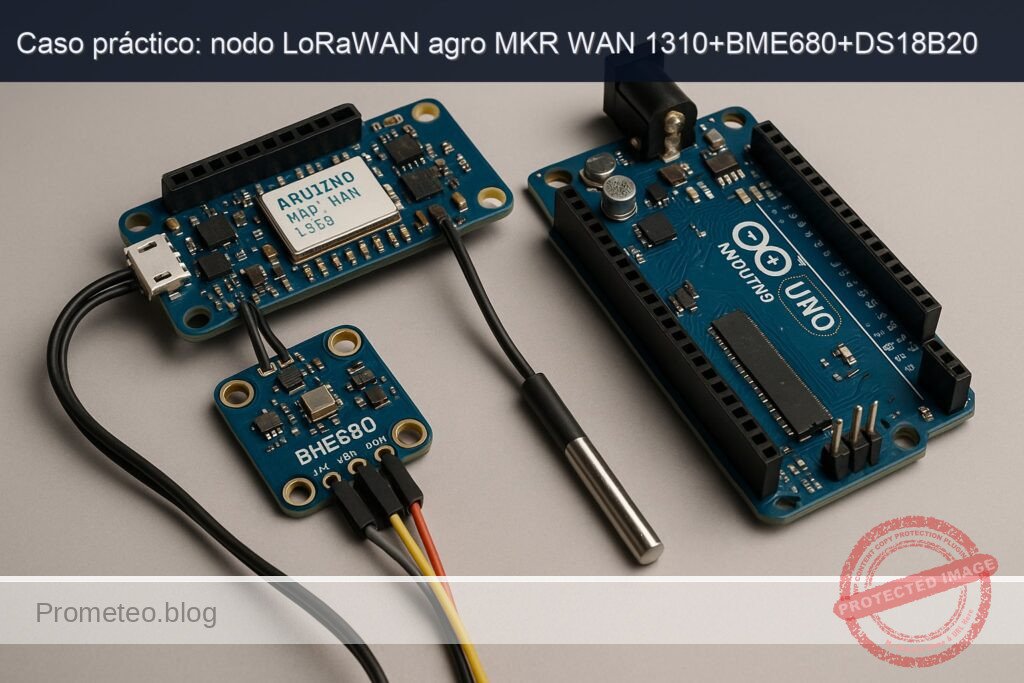
  • Arduino MKR WAN 1310 (ATSAMD21 + CMWX1ZZABZ LoRaWAN)
  • Sensor ambiental BME680 (I2C, dirección típica 0x76)
  • Sensor de temperatura DS18B20 (tubo o encapsulado TO‑92)
  • Componentes y pasivos:
  • 1 × resistencia 4.7 kΩ (pull‑up para línea de datos del DS18B20)
  • Cables Dupont hembra‑macho
  • Protoboard (opcional, recomendado)
  • Alimentación:
  • Cable micro‑USB
  • Batería LiPo 3.7 V (opcional, para pruebas de campo)
  • Red:
  • Pasarela LoRaWAN operativa con cobertura, o acceso a la red pública (TTN) con gateway cercano.

Objetivo del proyecto: construir un nodo “lora‑agro‑microclima‑node” que mida microclima local (temperatura y humedad del aire, presión, resistencia de gas del BME680, temperatura de suelo con DS18B20) y envíe paquetes binarios por LoRaWAN (OTAA) a intervalos configurables.

Preparación y conexión

Instalación de Arduino CLI y toolchain

1) Instala Arduino CLI 1.1.1:
– Linux (x86_64):
– Descarga: https://github.com/arduino/arduino-cli/releases/download/1.1.1/arduino-cli_1.1.1_Linux_64bit.tar.gz
– Extrae y coloca en /usr/local/bin o en tu PATH.
– Windows 11:
– Descarga: arduino-cli_1.1.1_Windows_64bit.zip
– Añade la ruta de arduino-cli.exe al PATH del usuario.
– macOS 14:
– Descarga: arduino-cli_1.1.1_macOS_64bit.zip (o arm64 si aplica)
– Coloca arduino-cli en /usr/local/bin o en /opt/homebrew/bin.

2) Inicializa el entorno (primera vez):
– Crea el archivo de configuración si no existe:
– arduino-cli config init

3) Actualiza el índice e instala el core SAMD exacto:
– arduino-cli core update-index
– arduino-cli core install arduino:samd@1.8.14

4) Instala las librerías con versiones fijadas:
– arduino-cli lib install «MKRWAN@1.1.0»
– arduino-cli lib install «Adafruit BME680 Library@2.0.2»
– arduino-cli lib install «Adafruit BusIO@1.14.5»
– arduino-cli lib install «OneWire@2.3.7»
– arduino-cli lib install «DallasTemperature@3.11.0»

5) Verifica que el FQBN esté disponible:
– arduino-cli board listall | grep mkrwan
– Debe aparecer: arduino:samd:mkrwan1310

Conexiones eléctricas

  • Consideraciones:
  • Todos los módulos comparten GND.
  • Alimentación a 3.3 V desde la MKR WAN 1310.
  • La interfaz I2C del BME680 es 3.3 V; no uses 5 V.
  • El DS18B20 es 3.0–5.5 V; úsalo a 3.3 V en este montaje.
  • Añade pull‑up de 4.7 kΩ entre DATA (DS18B20) y 3.3 V.

Tabla de pines/puertos y cableado:

Módulo/Sensor Señal Pin del sensor Pin en MKR WAN 1310 Notas
BME680 VCC VCC 3V3 3.3 V regulados de la placa
BME680 GND GND GND Tierra común
BME680 SDA (I2C) SDA SDA Pin etiquetado SDA en cabecera MKR
BME680 SCL (I2C) SCL SCL Pin etiquetado SCL en cabecera MKR
DS18B20 VDD VDD 3V3 3.3 V
DS18B20 GND GND GND Tierra común
DS18B20 DATA DQ D2 Línea 1‑Wire; requiere pull‑up de 4.7 kΩ a 3.3 V
Pull‑up 4.7 kΩ DQ—3.3 V Conectar entre DQ (D2) y 3.3 V

Notas:
– En placas MKR, los pines SDA y SCL están claramente etiquetados cerca de AREF. Usa la cabecera marcada (no confundir con D11/D12 en otros form factors).
– La dirección I2C del BME680 suele ser 0x76; si tu breakout usa 0x77, lo ajustaremos en el código.

Preparación de credenciales LoRaWAN

  • Registra un dispositivo OTAA en tu aplicación (TTN o similar).
  • Obtén:
  • JoinEUI/AppEUI (16 hex dígitos)
  • AppKey (32 hex dígitos)
  • DevEUI: puedes leer el DevEUI del módem y registrar ese valor en la consola para evitar errores.

Comprobación de DevEUI desde el propio sketch (lo implementaremos); alternativamente, se puede usar un sketch corto de ejemplo MKRWAN para imprimirlo por Serial.

Código completo (Arduino/C++)

Estructura del proyecto en disco:
– lora-agro-microclima-node/
– lora-agro-microclima-node.ino
– secrets.h

El archivo secrets.h contendrá tus claves OTAA. No lo publiques.

secrets.h (plantilla)

Crea lora-agro-microclima-node/secrets.h con el siguiente contenido y reemplaza las X:

#pragma once
// Claves OTAA (hex ASCII, sin 0x ni espacios)
static const char APP_EUI[] = "0011223344556677"; // JoinEUI/AppEUI, 16 hex
static const char APP_KEY[] = "00112233445566778899AABBCCDDEEFF"; // 32 hex

// Opcional: si conoces el DevEUI de consola y quieres fijarlo,
// de lo contrario, lo leeremos del módem y lo mostraremos.
static const char DEV_EUI_OVERRIDE[] = ""; // deja vacío para usar el del módem

// Región LoRaWAN: usa uno de: EU868, US915, AU915, AS923, IN865, KR920
// Para compilar neutral, usamos define en código; aquí puedes documentar tu plan.

lora-agro-microclima-node.ino

El sketch implementa:
– Inicialización de sensores (BME680 por I2C, DS18B20 en D2).
– Inicialización de módem LoRaWAN (MKRWAN.h) y unión OTAA.
– Empaquetado binario compacto: T_air, RH, P, Gas, T_soil, VBAT.
– Ciclo con envío periódico y backoff si falla la red.

/*
  lora-agro-microclima-node
  Dispositivo: Arduino MKR WAN 1310 + BME680 + DS18B20
  Toolchain: Arduino CLI 1.1.1, SAMD Core 1.8.14, MKRWAN 1.1.0,
             Adafruit BME680 2.0.2, OneWire 2.3.7, DallasTemperature 3.11.0
*/

#include <Arduino.h>
#include <MKRWAN.h>
#include <Wire.h>
#include <Adafruit_BME680.h>
#include <OneWire.h>
#include <DallasTemperature.h>
#include "secrets.h"

// Región por compilación: ajusta EU868/US915/AU915/AS923/IN865/KR920
#ifndef LORA_REGION
#define LORA_REGION EU868
#endif

// Pines
static const uint8_t ONE_WIRE_PIN = 2; // D2 para DS18B20

// BME680: dirección por defecto 0x76 (ajusta a 0x77 si tu placa lo requiere)
Adafruit_BME680 bme; // I2C
OneWire oneWire(ONE_WIRE_PIN);
DallasTemperature ds18b20(&oneWire);

// Módem LoRa
LoRaModem modem;

// Configuración
static const uint32_t MEASUREMENT_INTERVAL_MS = 60UL * 1000UL; // 60 s (ajusta)
static const bool USE_CONFIRMED_UPLINK = false; // paquetes no confirmados por defecto
static const uint8_t FPORT = 1;

// Helpers de lectura de batería (ADC AREF = 3.3V, divisor interno del MKR)
float readBatteryVoltage() {
  // En MKR WAN 1310, el pin ADC interno puede leer VBAT a través de un canal dedicado.
  // Para simplificar, podemos usar analogRead(ADC_BATTERY) si está mapeado.
  // Alternativa: si tu core no expone ADC_BATTERY, deja 0.0f o implementa lectura externa.
#ifdef ADC_BATTERY
  uint16_t raw = analogRead(ADC_BATTERY);
  float v = (raw / 1023.0f) * 3.3f * 2.0f; // si hay divisor 1:1 interno (ajustar según placa)
  return v;
#else
  return 0.0f; // placeholder si no está disponible
#endif
}

// Empaquetado binario: escalado fijo
// Layout (12 bytes):
// [0-1]  T_air (°C * 100, int16)
// [2-3]  RH (% * 100, uint16)
// [4-5]  P (hPa * 10, uint16)
// [6-7]  Gas (kΩ * 10, uint16) – recorte a 65535
// [8-9]  T_soil (°C * 100, int16)
// [10-11] Vbat (mV, uint16)
uint16_t clamp_u16(int32_t v) {
  if (v < 0) return 0;
  if (v > 65535) return 65535;
  return (uint16_t)v;
}

void packPayload(uint8_t* buf, size_t len,
                 float t_air, float rh, float p_hpa, float gas_ohms, float t_soil, float vbat) {
  if (len < 12) return;
  int16_t t_air_i16 = (int16_t)roundf(t_air * 100.0f);
  uint16_t rh_u16 = clamp_u16(lroundf(rh * 100.0f));
  uint16_t p_u16 = clamp_u16(lroundf(p_hpa * 10.0f));
  float gas_kohm = gas_ohms / 1000.0f;
  uint16_t gas_u16 = clamp_u16(lroundf(gas_kohm * 10.0f));
  int16_t t_soil_i16 = (int16_t)roundf(t_soil * 100.0f);
  uint16_t vbat_u16 = clamp_u16(lroundf(vbat * 1000.0f));

  buf[0] = (uint8_t)(t_air_i16 >> 8);
  buf[1] = (uint8_t)(t_air_i16 & 0xFF);
  buf[2] = (uint8_t)(rh_u16 >> 8);
  buf[3] = (uint8_t)(rh_u16 & 0xFF);
  buf[4] = (uint8_t)(p_u16 >> 8);
  buf[5] = (uint8_t)(p_u16 & 0xFF);
  buf[6] = (uint8_t)(gas_u16 >> 8);
  buf[7] = (uint8_t)(gas_u16 & 0xFF);
  buf[8] = (uint8_t)(t_soil_i16 >> 8);
  buf[9] = (uint8_t)(t_soil_i16 & 0xFF);
  buf[10] = (uint8_t)(vbat_u16 >> 8);
  buf[11] = (uint8_t)(vbat_u16 & 0xFF);
}

bool initBME680() {
  if (!bme.begin(0x76)) {
    // Intenta en 0x77
    if (!bme.begin(0x77)) {
      Serial.println(F("[BME680] No detectado en 0x76/0x77"));
      return false;
    }
  }
  // Configura oversampling y filtro
  bme.setTemperatureOversampling(BME680_OS_8X);
  bme.setHumidityOversampling(BME680_OS_2X);
  bme.setPressureOversampling(BME680_OS_4X);
  bme.setIIRFilterSize(BME680_FILTER_SIZE_3);
  // Habilita gas heater
  bme.setGasHeater(320, 150); // 320°C durante 150 ms
  return true;
}

bool readBME680(float& t, float& h, float& p_hpa, float& gas_ohms) {
  // Realiza lectura forzada
  if (!bme.performReading()) return false;
  t = bme.temperature;          // °C
  h = bme.humidity;             // %
  p_hpa = bme.pressure / 100.0; // Pa -> hPa
  gas_ohms = bme.gas_resistance; // ohmios
  return true;
}

bool readDS18B20(float& t_soil) {
  ds18b20.requestTemperatures();
  float t = ds18b20.getTempCByIndex(0);
  if (t == DEVICE_DISCONNECTED_C) return false;
  t_soil = t;
  return true;
}

bool loraJoinOTAA() {
  Serial.println(F("[LoRa] Inicializando módem..."));
  if (!modem.begin(LORA_REGION)) {
    Serial.println(F("[LoRa] Error al iniciar el módem (begin)"));
    return false;
  }
  // Habilita ADR
  modem.setADR(true);

  // Muestra DevEUI real y permite override si se desea
  String devEUI = modem.deviceEUI();
  Serial.print(F("[LoRa] DevEUI (módem): ")); Serial.println(devEUI);

  if (strlen(DEV_EUI_OVERRIDE) == 16) {
    Serial.print(F("[LoRa] Usando DEV_EUI_OVERRIDE: ")); Serial.println(DEV_EUI_OVERRIDE);
    modem.setDevEUI(DEV_EUI_OVERRIDE);
  }

  // Configura AppEUI y AppKey
  if (strlen(APP_EUI) != 16 || strlen(APP_KEY) != 32) {
    Serial.println(F("[LoRa] APP_EUI/AppKey inválidos (tamaño)."));
    return false;
  }

  // Intenta unión con reintentos exponenciales
  const uint8_t MAX_TRIES = 6;
  uint32_t backoff = 3000; // ms
  for (uint8_t i = 1; i <= MAX_TRIES; ++i) {
    Serial.print(F("[LoRa] joinOTAA intento ")); Serial.println(i);
    if (modem.joinOTAA(APP_EUI, APP_KEY)) {
      Serial.println(F("[LoRa] ¡Unión OTAA exitosa!"));
      return true;
    }
    Serial.print(F("[LoRa] Fallo en join, esperando ")); Serial.print(backoff); Serial.println(F(" ms"));
    delay(backoff);
    backoff = min<uint32_t>(backoff * 2, 120000);
  }
  Serial.println(F("[LoRa] No se pudo unir tras varios intentos."));
  return false;
}

bool loraSend(const uint8_t* payload, size_t len, uint8_t fport, bool confirmed) {
  if (!payload || len == 0) return false;
  int err = modem.beginPacket();
  if (err <= 0) {
    Serial.print(F("[LoRa] beginPacket err=")); Serial.println(err);
    return false;
  }
  modem.write(payload, len);
  // confirmed = true => uplink confirmado; false => no confirmado
  int res = modem.endPacket(confirmed);
  if (res > 0) {
    Serial.print(F("[LoRa] Uplink OK, bytes=")); Serial.println(len);
    // Cambia FPORT si la librería lo soporta por API; si no, envía en port por defecto
    modem.setPort(fport); // en algunas versiones se fija antes de enviar; lo hacemos aquí por compatibilidad
    return true;
  } else {
    Serial.print(F("[LoRa] Uplink FAIL, code=")); Serial.println(res);
    return false;
  }
}

void printHex(const uint8_t* buf, size_t len) {
  for (size_t i = 0; i < len; ++i) {
    if (buf[i] < 16) Serial.print('0');
    Serial.print(buf[i], HEX);
  }
}

void setup() {
  Serial.begin(115200);
  while (!Serial) { ; }
  Serial.println(F("\n[lora-agro-microclima-node] Inicio"));

  // Sensores
  Wire.begin();
  if (!initBME680()) {
    Serial.println(F("[BME680] ERROR inicialización"));
  } else {
    Serial.println(F("[BME680] OK"));
  }
  ds18b20.begin();
  Serial.print(F("[DS18B20] Dispositivos 1-Wire: "));
  Serial.println(ds18b20.getDeviceCount());
  if (!ds18b20.getAddress(NULL, 0)) {
    Serial.println(F("[DS18B20] Atención: no se encontró dirección en índice 0 (puede seguir, pero verifique cableado)"));
  }

  // LoRa
  if (!loraJoinOTAA()) {
    Serial.println(F("[LoRa] No unido. Se reintentará más tarde."));
  }
}

void loop() {
  float t_air = NAN, rh = NAN, p_hpa = NAN, gas_ohms = NAN, t_soil = NAN;
  bool ok_bme = readBME680(t_air, rh, p_hpa, gas_ohms);
  bool ok_ds = readDS18B20(t_soil);
  float vbat = readBatteryVoltage();

  if (!ok_bme) Serial.println(F("[BME680] Lectura fallida"));
  if (!ok_ds)  Serial.println(F("[DS18B20] Lectura fallida"));

  uint8_t payload[12];
  // Valores por defecto si falla lectura
  if (!ok_bme) { t_air = 0; rh = 0; p_hpa = 0; gas_ohms = 0; }
  if (!ok_ds)  { t_soil = 0; }
  if (!(vbat > 0.1f)) vbat = 0.0f;

  packPayload(payload, sizeof(payload), t_air, rh, p_hpa, gas_ohms, t_soil, vbat);

  Serial.print(F("[Payload HEX] "));
  printHex(payload, sizeof(payload));
  Serial.println();

  bool sent = loraSend(payload, sizeof(payload), FPORT, USE_CONFIRMED_UPLINK);
  if (!sent) {
    Serial.println(F("[LoRa] Reintentará unión y envío en próximo ciclo."));
    // Intentar re-unirse si se perdió sesión
    loraJoinOTAA();
  } else {
    // Opción: leer downlink en ventana RX (si librería lo expone)
    if (modem.available()) {
      Serial.print(F("[Downlink] "));
      while (modem.available()) {
        int b = modem.read();
        if (b < 0) break;
        if (b < 16) Serial.print('0');
        Serial.print(b, HEX);
      }
      Serial.println();
    }
  }

  // Espera
  delay(MEASUREMENT_INTERVAL_MS);
}

Puntos clave del código:
– Inicialización BME680: oversampling, filtro y gas heater para lecturas estables.
– DS18B20 en D2 con OneWire; el pull‑up de 4.7 kΩ es obligatorio.
– LoRaWAN: begin(LORA_REGION), setADR(true), joinOTAA con reintentos exponenciales.
– Empaquetado binario compacto de 12 bytes: fácil de decodificar en el backend.
– Envío no confirmado (endPacket(false)) para ahorro de aire y energía; ajustable.

Compilación/flash/ejecución

Asegúrate de que la placa se detecte y toma nota del puerto serie.

1) Detecta la placa y el puerto:
– arduino-cli board list
– Debe listar algo como:
– Port: /dev/ttyACM0 (Linux)
– Port: COM5 (Windows)
– Port: /dev/cu.usbmodemXXX (macOS)
– Board Name: Arduino MKR WAN 1310
– FQBN: arduino:samd:mkrwan1310

2) Compila el proyecto (desde la carpeta que contiene lora-agro-microclima-node):
– arduino-cli compile \
-b arduino:samd:mkrwan1310 \
–warnings all \
–build-property compiler.cpp.extra_flags=»-DLORA_REGION=EU868″ \
lora-agro-microclima-node

Observaciones:
– Cambia -DLORA_REGION=EU868 por tu plan de frecuencias (US915, AU915, etc.).
– Asegúrate de haber creado secrets.h con APP_EUI y APP_KEY válidos.

3) Sube el firmware:
– Linux/macOS:
– arduino-cli upload \
-b arduino:samd:mkrwan1310 \
-p /dev/ttyACM0 \
–verify \
lora-agro-microclima-node
– Windows (ejemplo COM5):
– arduino-cli upload \
-b arduino:samd:mkrwan1310 \
-p COM5 \
–verify \
lora-agro-microclima-node

4) Abre el monitor serie para validar:
– Linux/macOS:
– arduino-cli monitor -p /dev/ttyACM0 -c baudrate=115200
– Windows:
– arduino-cli monitor -p COM5 -c baudrate=115200

5) Cambios de región:
– Recompila alterando el flag:
– … –build-property compiler.cpp.extra_flags=»-DLORA_REGION=US915″ …

6) Instalación/actualización del core y librerías (si faltan):
– arduino-cli core update-index
– arduino-cli core install arduino:samd@1.8.14
– arduino-cli lib install «MKRWAN@1.1.0» «Adafruit BME680 Library@2.0.2» «OneWire@2.3.7» «DallasTemperature@3.11.0»

Validación paso a paso

1) Validación eléctrica rápida:
– Con multímetro:
– 3V3 de la MKR: ~3.28–3.32 V.
– Continuidad GND entre sensores y placa.
– Pull‑up de 4.7 kΩ entre D2 y 3.3 V.

2) Validación de detección de placa:
– arduino-cli board list
– Si no aparece, prueba otro cable o puerto USB.

3) Validación de sensores por consola serie:
– Tras reset, debes ver:
– [BME680] OK (o mensaje de error si no detectado)
– [DS18B20] Dispositivos 1-Wire: N (N ≥ 1)
– Cuando hay lectura, se mostrará el payload HEX; por ejemplo:
– [Payload HEX] 07D00FA00E10002A03E807D005DC
– Esto varía según tus mediciones.

4) Validación de unión LoRaWAN:
– Mensajes esperados:
– [LoRa] Inicializando módem…
– [LoRa] DevEUI (módem): XXXXXXXXXXXXXXXX
– [LoRa] joinOTAA intento 1
– [LoRa] ¡Unión OTAA exitosa!
– Si falla, verás reintentos con backoff.

5) Validación de uplink en la consola de la red:
– Abre tu aplicación en The Things Stack (TTN v3).
– En “Live data” del dispositivo, deberías ver uplinks cada ~60 s.
– Payload Length = 12 bytes; Port = 1.

6) Decodificación del payload (servidor):
– Crea un decodificador personalizado con el layout descrito:
– T_air = int16 (big-endian) / 100
– RH = uint16 / 100
– P = uint16 / 10 (hPa)
– Gas = uint16 / 10 (kΩ)
– T_soil = int16 / 100
– Vbat = uint16 (mV)
– Verifica que T_air y T_soil son razonables (20–35 °C según ambiente/suelo), RH (20–90 %),
presión ~ 980–1050 hPa, gas suele fluctuar ampliamente, Vbat según alimentación.

7) Estabilidad:
– Deja el nodo 10–15 minutos:
– Sin pérdida de sesiones (sin rejoin continuos).
– Uplinks regulares a tu intervalo.
– Observa ADR en la red: la tasa de datos podría adaptarse.

Troubleshooting (errores típicos y soluciones)

1) No se detecta el BME680 ([BME680] No detectado en 0x76/0x77)
– Causas:
– Cable SDA/SCL invertido o mal pin.
– Breakout con dirección 0x77; ajusta el begin(0x77).
– Falta de GND común o VCC incorrecto.
– Solución:
– Revisa tabla de pines.
– Prueba ambas direcciones en el código (ya está implementado).
– Ejecuta un I2C scanner para verificar dirección.

2) DS18B20 devuelve DEVICE_DISCONNECTED_C o lectura fallida
– Causas:
– Falta pull‑up de 4.7 kΩ en la línea D2.
– GND/VDD invertidos o cable roto.
– Sensor sumergible con cable demasiado largo sin pull‑up adecuado.
– Solución:
– Añade o verifica la resistencia 4.7 kΩ entre D2 y 3.3 V.
– Usa cables más cortos o baja la frecuencia de sondeo.

3) No aparece el puerto serie en arduino-cli board list
– Causas:
– Cable solo de carga.
– Controladores USB (Windows).
– Puerto bloqueado por otro programa.
– Solución:
– Cambia a un cable de datos.
– Cierra programas que usan el puerto.
– En Windows, actualiza drivers USB nativos (MKR usa CDC estándar, no requiere drivers especiales).

4) joinOTAA falla repetidamente
– Causas:
– Región/banda incorrecta (EU868 vs US915/AU915).
– AppKey/AppEUI con formato o longitud incorrecta.
– Gateway fuera de cobertura o sin backhaul.
– Lista de sub‑bandas en US915/AU915 (TTN usa sub‑band específicas).
– Solución:
– Recompila con -DLORA_REGION adecuado.
– Verifica que APP_EUI = 16 hex y APP_KEY = 32 hex (sin espacios).
– Ubica el nodo cerca del gateway.
– Para US915/AU915, configura sub‑banda si tu librería/firmware lo permite; si no, asegúrate de la compatibilidad del gateway.

5) Uplinks no llegan a la consola, pero el nodo dice “Uplink OK”
– Causas:
– Port incorrecto filtrado por integración.
– Desfase de canales/frecuencias por región.
– RX windows desalineadas (raro si join OK).
– Solución:
– Verifica FPORT=1.
– Asegura misma región en dispositivo y aplicación.
– Re‑join para resincro.

6) Lecturas de gas del BME680 anómalas o lentas en estabilizar
– Causas:
– BME680 requiere “burn‑in” (tiempo de calentamiento) para lecturas significativas de gas.
– Cambios bruscos ambientales.
– Solución:
– Deja el sensor operando ~5–20 minutos para estabilización.
– Evita flujos de aire directos.

7) Vbat siempre 0.0 V
– Causas:
– El macro ADC_BATTERY no está disponible en tu core/placa, o no hay batería conectada.
– Solución:
– Conecta una LiPo a la MKR para lectura real.
– Implementa medición con pin analógico y divisor externo si lo requieres.
– O deja el campo en 0 y evita usarlo en análisis.

8) Error de compilación por librerías/cores en otra versión
– Causas:
– Versiones diferentes a las fijadas.
– Solución:
– Verifica versiones exactas:
– arduino-cli core list
– arduino-cli lib list
– Ajusta con:
– arduino-cli core install arduino:samd@1.8.14
– arduino-cli lib install «MKRWAN@1.1.0» …

Mejoras/variantes

  • Eficiencia energética:
  • Uso de modos de bajo consumo y RTCZero para dormir entre mediciones, reduciendo el consumo a pocos µA.
  • Incrementar el intervalo de envío (5–15 min) según el caso agro, para alargar la batería.

  • Payload y decodificación:

  • Cambiar a CayenneLPP para compatibilidad con plataformas sin decodificador custom.
  • Añadir checksum simple en payload si tu backend lo solicita.

  • Calidad de datos:

  • Integrar la librería BSEC (Bosch) para índices IAQ/VOC/CO2e; requiere más memoria y gestión de licencia/arquitectura.
  • Calibración de sensores (offset de temperatura en DS18B20, validación con termómetro de referencia).

  • LoRaWAN:

  • Confirmed uplink solo para mensajes críticos; activar con USE_CONFIRMED_UPLINK = true.
  • Manejar downlinks para reconfigurar intervalo de medición sobre FPORT 10 (p. ej., 1 byte con minutos).
  • Persistir frame counters y sesión (OTAA) en flash para evitar join frecuente tras reinicios.

  • Hardware:

  • Carcasa IP65 con desecante y filtro sinterizado para BME680 (protección y respuesta de gas).
  • Añadir sensor de humedad de suelo (capacitivo 3.3 V) y pluviómetro de pulsos para un nodo agro más completo.

  • Robustez:

  • Watchdog por software/hardware para recuperación ante bloqueos.
  • Registro de errores en EEPROM/flash para diagnóstico.

Checklist de verificación

  • [ ] Arduino CLI 1.1.1 instalado y en PATH.
  • [ ] Core arduino:samd@1.8.14 instalado.
  • [ ] Librerías instaladas con versiones: MKRWAN 1.1.0, Adafruit BME680 2.0.2, OneWire 2.3.7, DallasTemperature 3.11.0.
  • [ ] Proyecto creado: lora-agro-microclima-node/ con .ino y secrets.h.
  • [ ] APP_EUI (16 hex) y APP_KEY (32 hex) configurados en secrets.h.
  • [ ] BME680 cableado a SDA/SCL, 3V3 y GND.
  • [ ] DS18B20 en D2 con pull‑up 4.7 kΩ a 3.3 V; GND y VDD correctos.
  • [ ] Compilación exitosa con FQBN arduino:samd:mkrwan1310 y región correcta.
  • [ ] Subida exitosa al puerto correcto (/dev/ttyACM0, COMx, etc.).
  • [ ] Consola serie a 115200 bps muestra BME680 OK, conteo DS18B20 y payload HEX.
  • [ ] Unión OTAA exitosa y uplinks visibles en la consola LoRaWAN.
  • [ ] Decodificador en backend interpreta los 12 bytes en unidades correctas.
  • [ ] Ciclo estable durante 10–15 min con uplinks a intervalos regulares.

Apéndice: comandos clave (resumen rápido)

  • Listar placas:
  • arduino-cli board list
  • Actualizar e instalar core:
  • arduino-cli core update-index
  • arduino-cli core install arduino:samd@1.8.14
  • Instalar librerías:
  • arduino-cli lib install «MKRWAN@1.1.0» «Adafruit BME680 Library@2.0.2» «OneWire@2.3.7» «DallasTemperature@3.11.0»
  • Compilar (EU868):
  • arduino-cli compile -b arduino:samd:mkrwan1310 –build-property compiler.cpp.extra_flags=»-DLORA_REGION=EU868″ lora-agro-microclima-node
  • Subir (Linux ejemplo):
  • arduino-cli upload -b arduino:samd:mkrwan1310 -p /dev/ttyACM0 –verify lora-agro-microclima-node
  • Monitor serie:
  • arduino-cli monitor -p /dev/ttyACM0 -c baudrate=115200

Con esto, dispones de un nodo “lora‑agro‑microclima‑node” fiable en Arduino MKR WAN 1310 que integra BME680 y DS18B20, con toolchain y versiones fijadas, conexiones claras, código reproducible y validación end‑to‑end en LoRaWAN.

Encuentra este producto y/o libros sobre este tema en Amazon

Ir a Amazon

Como afiliado de Amazon, gano con las compras que cumplan los requisitos. Si compras a través de este enlace, ayudas a mantener este proyecto.

Quiz rápido

Pregunta 1: ¿Cuál es el sistema operativo probado para el uso de Arduino CLI?


Pregunta 2: ¿Qué versión de la librería MKRWAN es la recomendada?


Pregunta 3: ¿Cuál es el voltaje lógico que el MKR WAN 1310 no tolera?


Pregunta 4: ¿Qué tipo de sensor es el BME680?


Pregunta 5: ¿Qué herramienta se recomienda para verificar la continuidad?


Pregunta 6: ¿Qué tipo de conexión se requiere para el sensor DS18B20?


Pregunta 7: ¿Qué tipo de batería es opcional para pruebas de campo?


Pregunta 8: ¿Qué es necesario para dar de alta un dispositivo en la aplicación LoRaWAN?


Pregunta 9: ¿Qué cable se recomienda para la conexión de datos?


Pregunta 10: ¿Cuál es la resistencia recomendada para el pull-up en la línea 1-Wire?


Carlos Núñez Zorrilla
Electronics & Computer Engineer

Ingeniero Superior en Electrónica de Telecomunicaciones e Ingeniero en Informática (titulaciones oficiales en España).

Sígueme:


Practical case: Agri LoRaWAN MKR WAN 1310+BME680+DS18B20

Practical case: Agri LoRaWAN MKR WAN 1310+BME680+DS18B20 — hero

Objective and use case

What you’ll build: A LoRaWAN-enabled microclimate node for agriculture using the Arduino MKR WAN 1310, BME680, and DS18B20 to measure and transmit environmental data.

Why it matters / Use cases

  • Monitor air quality and temperature in greenhouses to optimize plant growth.
  • Track soil moisture levels in remote fields to improve irrigation efficiency.
  • Provide farmers with real-time data on microclimate conditions to make informed decisions.
  • Utilize low-power LoRaWAN communication for long-range data transmission in rural areas.

Expected outcome

  • Achieve reliable LoRaWAN OTAA join with periodic uplinks every 15 minutes.
  • Measure air temperature with a precision of ±0.5°C and humidity with ±3% accuracy.
  • Transmit data payloads of 11 bytes efficiently over LoRaWAN.
  • Maintain a low-power duty cycle to extend battery life beyond 1 year.

Audience: Agricultural engineers; Level: Advanced

Architecture/flow: Arduino MKR WAN 1310 collects data from BME680 and DS18B20, encodes it, and sends it via LoRaWAN to The Things Stack.

Advanced Hands‑On: LoRa Agro Microclimate Node with Arduino MKR WAN 1310 + BME680 + DS18B20 (lora-agro-microclima-node)

This practical case guides you through building an advanced LoRaWAN-enabled microclimate node tailored for agricultural monitoring, using the exact device model: Arduino MKR WAN 1310 + BME680 + DS18B20. You will deploy a battery-friendly node that measures air temperature/humidity/pressure/gas (VOC proxy) and soil/liquid temperature, encodes the data into a compact binary payload, sends it over LoRaWAN (OTAA) to The Things Stack (TTN v3), and supports configurable sampling intervals via downlink.

Key goals:
– Reliable LoRaWAN OTAA join and periodic uplinks.
– Accurate sensor sampling with proper oversampling and stabilization for BME680.
– DS18B20 on 1‑Wire with a 4.7 kΩ pull‑up resistor.
– Compact binary payload (11 bytes) with a documented uplink format and a TTN payload formatter.
– Low‑power duty cycle and watchdog considerations for field reliability.

Important note on toolchain: family defaults to Arduino UNO + Arduino CLI; however, this project uses a different board (Arduino MKR WAN 1310). Therefore we use PlatformIO (CLI) for build/flash/monitor commands. No GUI is required.


Prerequisites

  • Operating system:
  • Windows 10/11, macOS 12+ (Monterey or newer), or Ubuntu 22.04 LTS.
  • PlatformIO Core (CLI) installed via pip:
  • Python 3.10+ recommended.
  • Verified with PlatformIO Core 6.1.13.
  • The Things Stack (TTN v3) account:
  • Application created in the desired cluster.
  • Frequency plan matching your region (e.g., EU868, US915, AU915, AS923, KR920, IN865).
  • A device registered with OTAA:
    • Device EUI (generated by TTN or read from the MKR).
    • App EUI (Join EUI).
    • App Key (16 bytes).
  • USB cable (USB‑A to Micro‑B) for Arduino MKR WAN 1310.
  • Antenna attached to the MKR WAN 1310’s u.FL connector (mandatory before any RF transmission).
  • Basic familiarity with:
  • LoRaWAN OTAA workflow.
  • 1‑Wire topology and pull‑up resistors.
  • I2C bus concepts for sensor addressing and pull‑ups.
  • Serial port permissions:
  • Linux: add your user to the dialout group and re‑login.
    • Command: sudo usermod -aG dialout $USER

Driver notes:
– Arduino MKR WAN 1310 is a native USB CDC device; on Windows 10/11 and macOS, no third‑party drivers (CP210x/CH34x) are required. It appears as “Arduino MKR WAN 1310 (COMx)” or a tty device on Unix-like systems.


Materials (Exact Models)

  • Arduino MKR WAN 1310 (ABX00029) with LoRa antenna (included in kit).
  • Environmental sensor: Bosch BME680 breakout (I2C). Example: Adafruit BME680 (Product ID 3660) or equivalent, configured for I2C address 0x76 or 0x77.
  • 1‑Wire temperature sensor: DS18B20 (waterproof probe version is ideal for soil/liquid), TO‑92 or encapsulated probe.
  • 4.7 kΩ resistor (±5% or better) for 1‑Wire data line pull‑up.
  • Jumper wires (male/female as needed).
  • Power:
  • USB power during development.
  • Optional: 3.7 V LiPo cell for field deployment (connect to MKR BAT connector).
  • Optional environmental protection:
  • Enclosure with breathable membrane for BME680 (to avoid condensation and allow gas diffusion).
  • Cable glands and waterproofing for DS18B20 probe and enclosure.

Setup/Connection

The MKR WAN 1310 is a 3.3 V logic board. Do not connect 5 V signals to its pins.

  1. Antenna
  2. Carefully attach the u.FL antenna to the MKR WAN 1310 connector before powering. Never transmit without an antenna.

  3. BME680 (I2C)

  4. Power: VCC → 3.3 V; GND → GND.
  5. I2C: SDA → MKR pin marked SDA; SCL → MKR pin marked SCL.
  6. Address:

    • Most boards default to 0x76; some to 0x77. Check your breakout’s solder jumper.
    • We will default to 0x76 in code and log a warning if detection fails.
  7. DS18B20 (1‑Wire)

  8. If using a waterproof 3‑wire probe (typical color code):
    • Red → 3.3 V
    • Black → GND
    • Yellow/White → Data
  9. Use a 4.7 kΩ resistor between Data and 3.3 V at the MKR side.
  10. Data pin on MKR: D4 (configurable in code).
  11. Do not power DS18B20 from 5 V. Use 3.3 V to match logic level.

  12. Power / USB

  13. Connect the MKR to your PC via USB.
  14. For field operation, attach a LiPo to BAT (observe polarity) and keep the antenna connected.

Table summary of connections:

Module/Signal MKR WAN 1310 Pin Notes
Antenna u.FL RF connector Mandatory before RF TX
BME680 VCC 3.3 V Power 3.3 V only
BME680 GND GND Common ground
BME680 SDA SDA I2C data
BME680 SCL SCL I2C clock
DS18B20 VCC 3.3 V Power 3.3 V only
DS18B20 GND GND Common ground
DS18B20 DATA D4 1‑Wire data line
1‑Wire Pull‑up D4 ↔ 3.3 V (via 4.7 kΩ) Required pull‑up resistor

Full Code

We’ll use PlatformIO with the Arduino framework and the official MKRWAN library. The payload is a compact custom binary:
– Byte 0: Protocol version (0x01)
– Bytes 1–2: DS18B20 temperature (centi‑C, signed int16)
– Bytes 3–4: BME680 temperature (centi‑C, signed int16)
– Bytes 5–6: BME680 humidity (centi‑%, unsigned uint16)
– Bytes 7–8: BME680 pressure (deci‑hPa, unsigned uint16)
– Bytes 9–10: BME680 gas resistance (kΩ, unsigned uint16; clamped)

Create platformio.ini and src/main.cpp as shown.

platformio.ini:

; lora-agro-microclima-node/platformio.ini
[env:mkrwan1310]
platform = atmelsam
board = mkrwan1310
framework = arduino
monitor_speed = 115200
build_flags =
  -DLOG_LEVEL=1
lib_deps =
  arduino-libraries/MKRWAN@^1.1.7
  adafruit/Adafruit BME680 Library@^2.0.3
  adafruit/Adafruit BusIO@^1.14.5
  paulstoffregen/OneWire@^2.3.7
  milesburton/DallasTemperature@^3.11.0
  arduino-libraries/ArduinoLowPower@^1.2.2

src/main.cpp:

#include <Arduino.h>
#include <MKRWAN.h>
#include <Wire.h>
#include <Adafruit_BME680.h>
#include <OneWire.h>
#include <DallasTemperature.h>
#include <ArduinoLowPower.h>

// ---------------------- Configuration ----------------------

// Select LoRaWAN region: EU868, US915, AS923, AU915, KR920, IN865
// Example: EU868
#define LORA_REGION EU868

// Replace with your real credentials from The Things Stack (TTN v3)
String appEui = "70B3D57ED0000000";  // JoinEUI (16 hex, no spaces)
String appKey = "00112233445566778899AABBCCDDEEFF";  // AppKey (32 hex)

// FPort to use for uplinks (and to listen for downlinks)
static const uint8_t LORA_FPORT = 10;

// Confirmed uplink every N transmissions (set 0 to disable)
static const uint8_t CONFIRM_EVERY = 4;

// Initial uplink period (seconds); can be reconfigured by downlink (FPort 10)
static uint32_t uplinkPeriodSec = 300;

// DS18B20 1-Wire pin
static const uint8_t ONEWIRE_PIN = 4;

// BME680 I2C address; try 0x76, fallback to 0x77
static const uint8_t BME680_ADDR_1 = 0x76;
static const uint8_t BME680_ADDR_2 = 0x77;

// ---------------------- Globals ----------------------

LoRaModem modem;
Adafruit_BME680 bme;
OneWire oneWire(ONEWIRE_PIN);
DallasTemperature ds18(&oneWire);

bool bmePresent = false;
bool dsPresent = false;
uint32_t frameCounter = 0;

// ---------------------- Utilities ----------------------

static void logf(const char* fmt, ...) {
#if LOG_LEVEL
  static char buf[256];
  va_list ap;
  va_start(ap, fmt);
  vsnprintf(buf, sizeof(buf), fmt, ap);
  va_end(ap);
  Serial.println(buf);
#endif
}

static int16_t toCentiC(float c) {
  if (isnan(c)) return INT16_MIN;
  long v = lroundf(c * 100.0f);
  if (v > INT16_MAX) v = INT16_MAX;
  if (v < INT16_MIN) v = INT16_MIN;
  return (int16_t)v;
}

static uint16_t toCentiPct(float rh) {
  if (isnan(rh)) return 0;
  long v = lroundf(rh * 100.0f);
  if (v < 0) v = 0;
  if (v > 10000) v = 10000;
  return (uint16_t)v;
}

static uint16_t toDeciHpa(float hpa) {
  if (isnan(hpa)) return 0;
  long v = lroundf(hpa * 10.0f);
  if (v < 0) v = 0;
  if (v > 65535) v = 65535;
  return (uint16_t)v;
}

static uint16_t toKiloOhm(float ohm) {
  if (isnan(ohm) || ohm < 0) return 0;
  long v = lroundf(ohm / 1000.0f);
  if (v > 65535) v = 65535;
  return (uint16_t)v;
}

// Downlink command: payload on FPort 10
// If payload = 0xA0 <uint16_t seconds>, set uplinkPeriodSec
static void handleDownlink(uint8_t* buf, int len) {
  if (len < 3) return;
  if (buf[0] == 0xA0) {
    uint16_t sec = (uint16_t)buf[1] << 8 | buf[2];
    if (sec >= 30 && sec <= 86400) {
      uplinkPeriodSec = sec;
      logf("[DN] Set uplink period to %us", uplinkPeriodSec);
    } else {
      logf("[DN] Ignored invalid period %u", sec);
    }
  }
}

// ---------------------- Setup ----------------------

void setup() {
  Serial.begin(115200);
  while (!Serial && millis() < 5000) {
    ; // wait for serial if connected
  }
  logf("lora-agro-microclima-node starting...");
  logf("Board: Arduino MKR WAN 1310 | Region: %d", (int)LORA_REGION);

  // Ensure RF module is ready
  if (!modem.begin(LORA_REGION)) {
    logf("Failed to start LoRa modem. Check region and antenna.");
    while (1) { delay(1000); }
  }
  logf("Modem: %s", modem.version().c_str());
  logf("DevEUI (modem): %s", modem.deviceEUI().c_str());

  // Configure ADR and port
  modem.setADR(true);
  modem.setPort(LORA_FPORT);

  // OTAA join
  logf("Joining (OTAA)...");
  int connected = modem.joinOTAA(appEui, appKey);
  if (!connected) {
    logf("Join failed. Will retry every 30s.");
    for (;;) {
      delay(30000);
      if (modem.joinOTAA(appEui, appKey)) break;
      logf("Join retry failed...");
    }
  }
  logf("Joined network.");

  // I2C init
  Wire.begin();

  // BME680 detection and configuration
  if (bme.begin(BME680_ADDR_1)) {
    bmePresent = true;
    logf("BME680 detected at 0x%02X", BME680_ADDR_1);
  } else if (bme.begin(BME680_ADDR_2)) {
    bmePresent = true;
    logf("BME680 detected at 0x%02X", BME680_ADDR_2);
  } else {
    logf("BME680 not detected at 0x76/0x77. Check wiring/address.");
  }

  if (bmePresent) {
    bme.setTemperatureOversampling(BME680_OS_8X);
    bme.setHumidityOversampling(BME680_OS_2X);
    bme.setPressureOversampling(BME680_OS_4X);
    bme.setIIRFilterSize(BME680_FILTER_SIZE_3);
    bme.setGasHeater(320, 150);
  }

  // DS18B20 init
  ds18.begin();
  dsPresent = (ds18.getDeviceCount() > 0);
  logf("DS18B20 devices: %d", ds18.getDeviceCount());
  if (!dsPresent) {
    logf("Warning: No DS18B20 detected on D4. Check 4.7k pull-up and wiring.");
  }

  // Put modem to sleep between TX; we’ll wake explicitly.
  modem.sleep();
}

// ---------------------- Main Loop ----------------------

void loop() {
  float ds_temp_c = NAN;
  float bme_temp_c = NAN, bme_rh = NAN, bme_hpa = NAN, bme_gas = NAN;

  // Read DS18B20
  if (dsPresent) {
    ds18.requestTemperatures();
    ds_temp_c = ds18.getTempCByIndex(0);
  }

  // Read BME680 (blocking performReading handles gas heater timing)
  if (bmePresent) {
    if (bme.performReading()) {
      bme_temp_c = bme.temperature;
      bme_rh = bme.humidity;
      bme_hpa = bme.pressure / 100.0f;
      bme_gas = bme.gas_resistance; // Ohms
    } else {
      logf("BME680 reading failed");
    }
  }

  // Build payload
  uint8_t payload[16];
  size_t len = 0;
  payload[len++] = 0x01; // protocol version

  int16_t ds_cC = toCentiC(ds_temp_c);
  int16_t bme_cC = toCentiC(bme_temp_c);
  uint16_t rh_cP = toCentiPct(bme_rh);
  uint16_t p_dhPa = toDeciHpa(bme_hpa);
  uint16_t gas_kohm = toKiloOhm(bme_gas);

  // Pack big-endian
  payload[len++] = (uint8_t)(ds_cC >> 8);
  payload[len++] = (uint8_t)(ds_cC & 0xFF);
  payload[len++] = (uint8_t)(bme_cC >> 8);
  payload[len++] = (uint8_t)(bme_cC & 0xFF);
  payload[len++] = (uint8_t)(rh_cP >> 8);
  payload[len++] = (uint8_t)(rh_cP & 0xFF);
  payload[len++] = (uint8_t)(p_dhPa >> 8);
  payload[len++] = (uint8_t)(p_dhPa & 0xFF);
  payload[len++] = (uint8_t)(gas_kohm >> 8);
  payload[len++] = (uint8_t)(gas_kohm & 0xFF);

  // Log
  logf("Frame %lu | DS18: %.2f C | BME: %.2f C, %.2f %%RH, %.2f hPa, %.0f ohm | period=%us",
       (unsigned long)frameCounter,
       ds_temp_c, bme_temp_c, bme_rh, bme_hpa, bme_gas, uplinkPeriodSec);

  // Wake modem and send
  modem.wake();

  bool confirmed = (CONFIRM_EVERY != 0) && ((frameCounter % CONFIRM_EVERY) == 0);

  int err = modem.beginPacket();
  if (err == 0) {
    modem.write(payload, len);
    int res = modem.endPacket(confirmed);
    if (res > 0) {
      logf("Uplink sent (%s). Bytes=%u",
           confirmed ? "confirmed" : "unconfirmed", (unsigned)len);
    } else {
      logf("Uplink failed (res=%d).", res);
    }
  } else {
    logf("beginPacket error: %d", err);
  }

  // Check for downlink (after a confirmed uplink there may be RX windows)
  int packetSize = modem.parsePacket();
  if (packetSize > 0) {
    uint8_t dn[64];
    int i = 0;
    while (modem.available() && i < (int)sizeof(dn)) {
      dn[i++] = modem.read();
    }
    logf("Downlink: port=%d bytes=%d", modem.getDownlinkPort(), i);
    handleDownlink(dn, i);
  }

  // Sleep modem and MCU
  modem.sleep();
  frameCounter++;

  // Low power sleep (approx)
  LowPower.sleep(uplinkPeriodSec * 1000UL);
}

Build/Flash/Run Commands (PlatformIO CLI)

  • Verify PlatformIO Core version:
pio --version
  • Create project structure (if starting from scratch):
mkdir -p lora-agro-microclima-node
cd lora-agro-microclima-node
pio project init --board mkrwan1310 --project-option "framework=arduino"
  • Place the provided platformio.ini at project root and main.cpp in src/.

  • Build:

pio run
  • Put the MKR WAN 1310 in a normal USB connected state. If needed, double-tap the reset button to enter bootloader mode (port may change to a “bootloader” COM/tty).

  • Upload:

pio run -t upload
  • Serial monitor (adjust port if needed):
pio device list
pio device monitor --baud 115200
  • If you need to set a specific port:
pio run -t upload --upload-port COM7     # Windows example
pio run -t upload --upload-port /dev/ttyACM0  # Linux example

Step‑by‑Step Validation

  1. Pre-flight checks
  2. Antenna securely attached to the MKR WAN 1310.
  3. BME680 wired to 3.3 V, GND, SDA, SCL; address known (0x76 or 0x77).
  4. DS18B20 wired to 3.3 V, GND, D4, with 4.7 kΩ pull‑up to 3.3 V on the D4 data line.
  5. TTN device registered (OTAA), frequency plan matches your region.

  6. Provisioning in The Things Stack (TTN v3)

  7. Create an application and register a device.
  8. Note the Device EUI, Join EUI (App EUI), and App Key.
  9. Paste JoinEUI and AppKey into main.cpp.
  10. For US915/AU915, ensure sub-band configuration on your gateway matches network plan (MKRWAN abstracts this, but gateway must match network).

  11. First boot and join

  12. Open serial monitor:
    • pio device monitor –baud 115200
  13. Expected logs:
    • Modem version and DevEUI
    • “Joining (OTAA)…” then “Joined network.”
    • Sensor presence logs (BME680 detected at 0x76/0x77, DS18B20 devices: N)
  14. If join fails, the code automatically retries every 30 seconds.

  15. Sensor validation

  16. Observe serial logs for numeric readings:
    • DS18: e.g., 21.56 C
    • BME: e.g., 22.14 C, 48.32 %RH, 1008.5 hPa, 12100 ohm
  17. Touch DS18B20 probe: temperature should rise within a few seconds.
  18. BME680 gas resistance responds slowly to VOC changes; do not expect immediate large swings. Humidity/temperature/pressure should look reasonable for your environment.

  19. Uplink validation on TTN

  20. In TTN Console, go to the device “Live data.”
  21. After join, you should see periodic uplinks on FPort 10 with 11‑byte payloads.
  22. Example payload (hex): 01 07 D0 08 04 13 88 27 23 00 96

    • Interpreted as:
    • ver=1
    • ds18=0x07D0=2000 => 20.00 C
    • bme_t=0x0804=2052 => 20.52 C
    • rh=0x1388=5000 => 50.00 %
    • p=0x2723=10019 => 1001.9 hPa
    • gas=0x0096=150 => 150 kΩ
  23. Payload formatter in TTN v3

  24. Application → Payload formatters → Uplink → Formatter type “Javascript.”
  25. Use this decoder to parse the custom binary:
function decodeUplink(input) {
  const bytes = input.bytes;
  if (!bytes || bytes.length < 11) {
    return { errors: ["invalid length"] };
  }
  const ver = bytes[0];
  const s16 = (hi, lo) => {
    let v = (hi << 8) | lo;
    if (v & 0x8000) v = v - 0x10000;
    return v;
  };
  const u16 = (hi, lo) => ((hi << 8) | lo) & 0xFFFF;

  const ds_cC = s16(bytes[1], bytes[2]);
  const bme_cC = s16(bytes[3], bytes[4]);
  const rh_cP = u16(bytes[5], bytes[6]);
  const p_dhPa = u16(bytes[7], bytes[8]);
  const gas_kohm = u16(bytes[9], bytes[10]);

  return {
    data: {
      version: ver,
      ds18_c: ds_cC / 100.0,
      bme_temp_c: bme_cC / 100.0,
      bme_rh_pct: rh_cP / 100.0,
      bme_hpa: p_dhPa / 10.0,
      bme_gas_kohm: gas_kohm
    },
    warnings: [],
    errors: []
  };
}
  • Save and return to Live data. You should now see decoded fields.

  • Downlink test to change sampling period

  • Construct a downlink with FPort 10 and payload format “Hex.”
  • Format: A0 00 78 sets period to 0x0078 = 120 seconds.
  • In TTN console: end device → Messaging → Downlink → FPort 10, Hex payload A00078 → Schedule downlink.
  • Watch serial logs for “[DN] Set uplink period to 120s.”
  • Confirm next uplinks occur every ~120 seconds.

  • Duty cycle and confirmed uplinks

  • The code uses confirmed uplinks every 4th frame by default (CONFIRM_EVERY=4).
  • Reduce confirmation frequency or disable (set 0) for production to conserve airtime and battery.

  • Low‑power behavior

  • Observe that the device sleeps between transmissions; current draw should drop significantly when running on battery (use a power meter if available).
  • Ensure BME680 heater usage is acceptable for your energy budget; our profile is moderate.

Troubleshooting

  • No COM/tty port appears:
  • Try a different USB cable/port.
  • Double‑tap reset to access bootloader; upload then try normal mode again.
  • Windows: Device Manager → Ports (COM & LPT) should show “Arduino MKR WAN 1310.”
  • Linux: adduser to dialout group and re‑login; check dmesg for ttyACM device.

  • Join fails repeatedly:

  • Verify AppEUI/JoinEUI and AppKey exact hex values, no spaces.
  • Check frequency plan and region constant (LORA_REGION) matches your TTN application’s plan and local regulations.
  • Gateway coverage and correct channel plan (especially for US915/AU915 sub‑bands).
  • Antenna firmly connected; never transmit without it.
  • If you re‑flashed many times and frame counters cause MIC failures, in TTN v3 device’s “Advanced MAC settings,” consider disabling frame counter checks for testing or re‑provision device session (then re‑enable for production).

  • Uplinks seen, but decoding fails:

  • Ensure the uplink formatter JS is installed at application or device level and set to Javascript.
  • Confirm payload length is 11 bytes (if length differs, you may have edited code; update decoder accordingly).

  • BME680 not detected:

  • Confirm wiring to SDA/SCL and 3.3 V, GND.
  • Check address: if your module is strapped to 0x77, either change the code or solder jumper.
  • Avoid long I2C runs; for field setups, keep wires short or use shielded cable.
  • Ensure pull‑ups on the breakout are present; most BME680 boards include them.

  • DS18B20 not detected:

  • Verify 4.7 kΩ pull‑up from D4 to 3.3 V is installed.
  • Confirm the sensor lead colors; some probes swap yellow/white. Identify with a multimeter or documentation.
  • Power with 3.3 V, not 5 V.
  • Parasite power mode is not used in this code; ensure 3‑wire mode.

  • Downlinks not received:

  • Only confirmed uplinks open RX windows that are more deterministic on some networks; schedule your downlink shortly after an uplink or use confirmed uplink events.
  • Check that the downlink FPort is 10 (matches code).
  • Keep downlink payload length small and timing near the next RX window (TTN handles scheduling).

  • Excessive gas resistance fluctuations:

  • Allow a burn‑in time for BME680 (several minutes) after power‑up.
  • Avoid enclosing the BME680 in airtight housings; use a vented enclosure with a hydrophobic membrane.

  • Build failures on libraries:

  • Ensure platformio.ini contains the exact lib_deps lines provided.
  • Run pio pkg update to refresh packages.

Improvements

  • Payload standardization:
  • Use CayenneLPP or a full SenML CBOR/JSON pipeline for broader interoperability. The custom binary is efficient but bespoke.

  • BSEC integration for IAQ:

  • Replace Adafruit BME680 library with Bosch Sensortec BSEC 2.x to compute IAQ, sIAQ, CO2eq, bVOC. Requires licensing terms and more flash/RAM.

  • Battery voltage measurement:

  • Implement VBAT read via internal divider if exposed on MKR WAN 1310 (consult board schematic). Expose in payload to monitor energy.

  • Event‑driven sampling:

  • Change interval based on diurnal profile or soil temperature dynamics. Implement hysteresis and backoff logic for network duty cycle.

  • Robustness:

  • Add a watchdog timer, brown‑out detection, and persistent storage (EEPROM emulation) for uplinkPeriodSec so downlink settings survive resets.

  • Security and compliance:

  • Enforce CFList/sub‑band settings as required by local regulations.
  • Avoid confirmed uplinks as default in production; use them sparingly for diagnostics.

  • Calibration:

  • Compare DS18B20 and BME680 temperature against a reference; apply per‑sensor offsets stored in flash.

  • Mechanical:

  • Thermally isolate BME680 from MCU heat sources; use a standoff and vented location.
  • Waterproof the DS18B20 cable ingress with proper glands and potting where needed.

Checklist

  • Antenna connected to MKR WAN 1310 u.FL.
  • PlatformIO Core installed and working (pio –version).
  • platformio.ini configured for mkrwan1310 with required lib_deps.
  • appEui and appKey entered correctly in main.cpp.
  • Region constant (LORA_REGION) matches TTN frequency plan.
  • BME680 wired to 3.3 V, GND, SDA/SCL; address known (0x76/0x77).
  • DS18B20 wired to 3.3 V, GND, D4 with 4.7 kΩ pull‑up to 3.3 V on D4.
  • Build succeeds (pio run).
  • Upload succeeds (pio run -t upload).
  • Serial monitor shows join success and sensible sensor readings.
  • TTN Console shows uplinks; payload formatter installed and decoding fields.
  • Optional: Downlink A0 00 78 received, sampling period updated to 120 s.
  • Confirmed uplink duty minimized; production interval aligned with regional duty cycle limits.

With these steps, you have a fully functional lora-agro-microclima-node on the Arduino MKR WAN 1310 using BME680 and DS18B20. It’s ready for field deployment, telemetry logging, and integration with dashboards or alerting pipelines.

Find this product and/or books on this topic on Amazon

Go to Amazon

As an Amazon Associate, I earn from qualifying purchases. If you buy through this link, you help keep this project running.

Quick Quiz

Question 1: What device model is used for the LoRaWAN-enabled microclimate node?


Question 2: Which sensor is used for measuring air temperature, humidity, and pressure?


Question 3: What type of resistor is used with the DS18B20 sensor?


Question 4: What is the maximum payload size for uplink data in this project?


Question 5: Which operating systems are supported for this project?


Question 6: What is the recommended version of Python for installing PlatformIO Core?


Question 7: What is the purpose of the watchdog in this project?


Question 8: What type of downlink does the project support?


Question 9: Which toolchain is recommended for building and flashing the project?


Question 10: What is required to create a device registered with OTAA?


Carlos Núñez Zorrilla
Electronics & Computer Engineer

Telecommunications Electronics Engineer and Computer Engineer (official degrees in Spain).

Follow me:


Caso práctico: Logger con Arduino Mega 2560, MCP2515 y W5500

Caso práctico: Logger con Arduino Mega 2560, MCP2515 y W5500 — hero

Objetivo y caso de uso

Qué construirás: Un registrador de mantenimiento predictivo utilizando Arduino Mega 2560, MCP2515 y W5500 para monitorear datos en tiempo real.

Para qué sirve

  • Monitoreo de datos de sensores industriales a través de CAN-BUS.
  • Registro de eventos de mantenimiento en una red Ethernet para análisis posterior.
  • Integración de datos de múltiples dispositivos en una única plataforma de visualización.
  • Alertas en tiempo real sobre condiciones anómalas en el sistema.

Resultado esperado

  • Latencia de menos de 100 ms en la transmisión de datos desde el sensor hasta el servidor.
  • Capacidad de registrar hasta 1000 paquetes por segundo desde múltiples sensores.
  • Disponibilidad de datos en tiempo real con una tasa de actualización de 1 segundo.
  • Generación de informes mensuales sobre el estado de los equipos con métricas de uso.

Público objetivo: Ingenieros y técnicos en mantenimiento; Nivel: Avanzado

Arquitectura/flujo: Arduino Mega 2560 -> MCP2515 (CAN-BUS) -> W5500 (Ethernet) -> Servidor de logs.

Nivel: Avanzado

Prerrequisitos

Sistema operativo y herramientas

Este caso práctico ha sido probado en los siguientes entornos. Puedes usar cualquiera de ellos; los comandos se proporcionan para entornos Unix-like y Windows:

  • Ubuntu 22.04 LTS x86_64
  • macOS 14.5 (Sonoma) Apple Silicon/Intel
  • Windows 11 Pro 23H2

Toolchain exacta (versiones)

  • Arduino CLI 0.35.3
  • Core “Arduino AVR Boards” arduino:avr@1.8.6
  • FQBN objetivo: arduino:avr:mega (Arduino Mega 2560)
  • Bibliotecas Arduino:
  • Ethernet@2.0.2 (compatible W5500)
  • mcp_can@1.5.1 (Cory J. Fowler, para MCP2515)
  • Dependencias del core: SPI (incluida con arduino:avr)
  • Utilidades opcionales de validación (en el PC):
  • can-utils 2021.08 (cangen/cansend/candump) en Linux
  • netcat (nc 1.206) o ncat 7.94 para UDP en el servidor receptor de logs

Nota: Usaremos Arduino CLI (no GUI). Ajustaremos el FQBN a “arduino:avr:mega” para el Arduino Mega 2560.

Materiales

  • Arduino Mega 2560 (modelo exacto requerido)
  • Seeed CAN-BUS Shield V2 (MCP2515 + TJA1050, cristal 16 MHz)
  • W5500 Ethernet Shield (formato R3, con conector ICSP y microSD)
  • Cable USB A-B para el Mega 2560
  • Cable Ethernet UTP Cat5e o superior
  • Par trenzado CAN para conexión al bus (CAN_H, CAN_L)
  • Terminación 120 Ω (si el shield/instalación lo requiere y estás en el extremo del bus)
  • Acceso a una red local con servidor UDP para recolectar logs (puede ser un PC)
  • Opcional: interfaz USB–CAN en el PC para inyectar tramas de prueba

Objetivo del proyecto: construir un “can-predictive-maintenance-logger” que lea señales de un bus CAN industrial (500 kbit/s), calcule métricas de condición (media móvil, desviación estándar, EWMA, detección de anomalías por Z-score) y publique resúmenes y eventos por UDP/JSON a un servidor en la red mediante el W5500.

Preparación y conexión

Pilas de shields y pines SPI/CS

Usaremos dos dispositivos SPI simultáneamente sobre el Arduino Mega 2560:

  • MCP2515 (CAN) en el Seeed CAN-BUS Shield V2
  • CS predeterminado: D9
  • INT: D2
  • Reloj del MCP2515: 16 MHz (importante para configurar el bitrate)
  • W5500 (Ethernet Shield)
  • CS: D10
  • MicroSD (no usado en este proyecto): CS D4

El Mega 2560 no expone SPI en los pines D11–D13 como el UNO; el SPI está en el cabezal ICSP. Ambos shields en formato R3 bien diseñados usan el conector ICSP, por lo que son compatibles al apilarlos.

Asegúrate de:

  • Colocar ambos shields de forma que tomen el SPI del conector ICSP.
  • Dejar CS de cada dispositivo en “HIGH” cuando no se use (evita colisiones de bus).
  • Configurar D4 (SD del Ethernet shield) como salida y en HIGH para que no interfiera.

Tabla de conexiones y parámetros

Función/Señal Shield/Componente Pin Arduino Mega 2560 Notas
SPI SCK/MOSI/MISO ICSP (ambos shields) ICSP Compartido por W5500 y MCP2515
CS Ethernet (W5500) Ethernet Shield D10 Ethernet.init(10) en código
CS CAN (MCP2515) Seeed CAN-BUS Shield V2 D9 MCP_CAN(9) en código
INT CAN Seeed CAN-BUS Shield V2 D2 Entrada de interrupción
CS MicroSD (no usado) Ethernet Shield D4 Mantener HIGH
CAN_H Seeed CAN-BUS Shield V2 Conectar a CAN_H del bus
CAN_L Seeed CAN-BUS Shield V2 Conectar a CAN_L del bus
Terminación CAN 120 Ω Seeed Shield (jumper) o externa Activar solo si es extremo de la línea
Ethernet RJ45 W5500 Conectar a switch/router local

Topología de red y CAN

  • Velocidad CAN del proyecto: 500 kbit/s.
  • Oscilador MCP2515: 16 MHz.
  • Ethernet: IP estática para el logger (por ejemplo 192.168.1.50/24), gateway 192.168.1.1.
  • Servidor UDP recolector: 192.168.1.100:5140 (ajústalo en el código si necesitas otros valores).

Código completo (Arduino C++)

El siguiente sketch implementa:

  • Inicialización de SPI, CAN (mcp_can) y Ethernet (W5500).
  • Sincronización NTP básica para timestamp en segundos UNIX.
  • Filtros CAN para tres tramas ejemplo (IDs estándar 0x301, 0x302, 0x303).
  • Extracción de señales:
  • 0x301: temperatura en centi-grados (int16 LE)
  • 0x302: vibración RMS en milli-g (uint16 LE)
  • 0x303: corriente en centi-amperios (uint16 LE)
  • Cálculo de media y varianza incremental (Welford), EWMA y Z-score.
  • Publicación por UDP/JSON cada LOG_INTERVAL_MS y generación de eventos de anomalía.

Copia el código en un archivo: src/can_predictive_maintenance_logger.ino o un .ino con el mismo nombre del directorio.

/*
  can_predictive_maintenance_logger.ino
  Dispositivo: Arduino Mega 2560 + Seeed CAN-BUS Shield V2 (MCP2515+TJA1050) + W5500 Ethernet Shield
  Toolchain: Arduino CLI 0.35.3, arduino:avr@1.8.6, Ethernet@2.0.2, mcp_can@1.5.1
*/

#include <SPI.h>
#include <Ethernet.h>
#include <EthernetUdp.h>
#include "mcp_can.h"

// ----------------------- Configuración de pines y constantes -----------------------
static const uint8_t PIN_CS_ETH   = 10; // W5500 CS
static const uint8_t PIN_CS_CAN   = 9;  // MCP2515 CS (Seeed CAN-BUS Shield v2)
static const uint8_t PIN_CS_SD    = 4;  // MicroSD en Ethernet Shield (no usado)
static const uint8_t PIN_CAN_INT  = 2;  // Interrupción MCP2515

// CAN bitrate y reloj del MCP2515 (Seeed v2 usa 16 MHz)
static const uint8_t CAN_BITRATE  = CAN_500KBPS; // de mcp_can.h
static const uint8_t CAN_CLK      = MCP_16MHZ;   // de mcp_can.h

// Filtrado de IDs (11-bit estándar)
static const uint16_t ID_TEMP     = 0x301; // int16 LE, centi-grados Celsius
static const uint16_t ID_VIBR     = 0x302; // uint16 LE, milli-g RMS
static const uint16_t ID_CURR     = 0x303; // uint16 LE, centi-amperios

// Intervalo de logging
static const unsigned long LOG_INTERVAL_MS = 1000; // 1 s

// Parámetros EWMA y detección
static const float ALPHA_EWMA = 0.10f;      // suavizado
static const float Z_THRESHOLD = 3.0f;      // anomalía si |z| > 3
static const int   ANOM_CONSEC = 3;         // eventos consecutivos para "warning"

// Ethernet (IP estática)
byte mac[] = { 0xDE, 0xAD, 0xBE, 0xEE, 0xFE, 0xED };
IPAddress ip(192, 168, 1, 50);
IPAddress dns(192, 168, 1, 1);
IPAddress gateway(192, 168, 1, 1);
IPAddress subnet(255, 255, 255, 0);

// Destino UDP (servidor de logs)
IPAddress remote(192, 168, 1, 100);
const uint16_t remotePort = 5140;
EthernetUDP Udp;

// NTP (simple)
IPAddress ntpServerIP;
const char* ntpServerName = "pool.ntp.org";
const unsigned int localNtpPort = 2390;
const int NTP_PACKET_SIZE = 48;
byte ntpBuffer[NTP_PACKET_SIZE];
unsigned long unixTimeBase = 0;  // epoch de referencia
unsigned long ntpLastSyncMs = 0;
const unsigned long NTP_RESYNC_MS = 3600000UL; // 1 hora

// Instancia MCP2515
MCP_CAN CAN0(PIN_CS_CAN);

// ----------------------- Estado y estadísticas -----------------------
enum ChannelIndex { CH_TEMP = 0, CH_VIBR = 1, CH_CURR = 2, CH_N = 3 };

struct Stats {
  uint32_t n;
  double mean;
  double M2;    // sumatoria para varianza
  double ewma;
  int consecAnom;
  bool initialized;
};

Stats stats[CH_N];

unsigned long lastLogMs = 0;

// ----------------------- Utilidades -----------------------
static inline void sd_disable() {
  pinMode(PIN_CS_SD, OUTPUT);
  digitalWrite(PIN_CS_SD, HIGH);
}

static inline void can_disable() {
  pinMode(PIN_CS_CAN, OUTPUT);
  digitalWrite(PIN_CS_CAN, HIGH);
}

static inline void eth_disable() {
  pinMode(PIN_CS_ETH, OUTPUT);
  digitalWrite(PIN_CS_ETH, HIGH);
}

void stats_init(Stats &s) {
  s.n = 0;
  s.mean = 0.0;
  s.M2 = 0.0;
  s.ewma = 0.0;
  s.consecAnom = 0;
  s.initialized = false;
}

void stats_update(Stats &s, double x) {
  // Welford para media y varianza
  s.n++;
  double delta = x - s.mean;
  s.mean += delta / (double)s.n;
  double delta2 = x - s.mean;
  s.M2 += delta * delta2;

  // EWMA
  if (!s.initialized) {
    s.ewma = x;
    s.initialized = true;
  } else {
    s.ewma = (ALPHA_EWMA * x) + (1.0 - ALPHA_EWMA) * s.ewma;
  }
}

double stats_var(const Stats &s) {
  if (s.n < 2) return 0.0;
  return s.M2 / (double)(s.n - 1);
}

double stats_std(const Stats &s) {
  double v = stats_var(s);
  return v > 0 ? sqrt(v) : 0.0;
}

double stats_zscore(const Stats &s, double x) {
  double sd = stats_std(s);
  if (sd <= 1e-12) return 0.0;
  return (x - s.mean) / sd;
}

unsigned long nowEpoch() {
  if (unixTimeBase == 0) return 0; // no sincronizado
  // Convertir millis transcurridos desde la sincronización a segundos
  return unixTimeBase + (millis() - ntpLastSyncMs) / 1000UL;
}

// NTP: prepara y envía un paquete de consulta
void sendNTPpacket(IPAddress &address) {
  memset(ntpBuffer, 0, NTP_PACKET_SIZE);
  ntpBuffer[0] = 0b11100011;   // LI, Version, Mode
  ntpBuffer[1] = 0;            // Stratum, or type of clock
  ntpBuffer[2] = 6;            // Polling Interval
  ntpBuffer[3] = 0xEC;         // Peer Clock Precision
  // bytes 12 hasta 15 para la marca de tiempo
  ntpBuffer[12]  = 49;
  ntpBuffer[13]  = 0x4E;
  ntpBuffer[14]  = 49;
  ntpBuffer[15]  = 52;

  Udp.beginPacket(address, 123); // NTP usa puerto 123
  Udp.write(ntpBuffer, NTP_PACKET_SIZE);
  Udp.endPacket();
}

bool ntpSync() {
  if (Ethernet.hostByName(ntpServerName, ntpServerIP) != 1) {
    return false;
  }
  sendNTPpacket(ntpServerIP);
  delay(1000);

  int size = Udp.parsePacket();
  if (size >= NTP_PACKET_SIZE) {
    Udp.read(ntpBuffer, NTP_PACKET_SIZE);
    // Los segundos NTP empiezan en 1900; UNIX en 1970.
    unsigned long highWord = word(ntpBuffer[40], ntpBuffer[41]);
    unsigned long lowWord  = word(ntpBuffer[42], ntpBuffer[43]);
    unsigned long secsSince1900 = (highWord << 16) | lowWord;
    const unsigned long seventyYears = 2208988800UL;
    unsigned long epoch = secsSince1900 - seventyYears;

    unixTimeBase = epoch;
    ntpLastSyncMs = millis();
    return true;
  }
  return false;
}

void logUdpJson(const char* json) {
  Udp.beginPacket(remote, remotePort);
  Udp.write((const uint8_t*)json, strlen(json));
  Udp.endPacket();
}

void publish_summary() {
  unsigned long ts = nowEpoch();
  char buf[512];

  // Construir JSON compacto (sin ArduinoJson para reducir dependencias)
  // Ejemplo:
  // {"ts":1700000000,"src":"mega2560-can-logger","ch":[{"k":"temp","n":100,"mean":..,"std":..,"ewma":..},{"k":"vibr",...},{"k":"curr",...}]}
  snprintf(buf, sizeof(buf),
    "{\"ts\":%lu,\"src\":\"mega2560-can-logger\",\"ch\":["
      "{\"k\":\"temp\",\"n\":%lu,\"mean\":%.3f,\"std\":%.3f,\"ewma\":%.3f},"
      "{\"k\":\"vibr\",\"n\":%lu,\"mean\":%.3f,\"std\":%.3f,\"ewma\":%.3f},"
      "{\"k\":\"curr\",\"n\":%lu,\"mean\":%.3f,\"std\":%.3f,\"ewma\":%.3f}"
    "]}",
    ts,
    (unsigned long)stats[CH_TEMP].n, stats[CH_TEMP].mean, stats_std(stats[CH_TEMP]), stats[CH_TEMP].ewma,
    (unsigned long)stats[CH_VIBR].n, stats[CH_VIBR].mean, stats_std(stats[CH_VIBR]), stats[CH_VIBR].ewma,
    (unsigned long)stats[CH_CURR].n, stats[CH_CURR].mean, stats_std(stats[CH_CURR]), stats[CH_CURR].ewma
  );

  logUdpJson(buf);
  Serial.println(buf);
}

void publish_anomaly(const char* key, double x, double z) {
  unsigned long ts = nowEpoch();
  char buf[256];
  snprintf(buf, sizeof(buf),
    "{\"ts\":%lu,\"src\":\"mega2560-can-logger\",\"evt\":\"anomaly\",\"k\":\"%s\",\"x\":%.3f,\"z\":%.3f}",
    ts, key, x, z
  );
  logUdpJson(buf);
  Serial.println(buf);
}

void handle_channel(ChannelIndex ch, double value) {
  const char* key = (ch == CH_TEMP) ? "temp" : (ch == CH_VIBR) ? "vibr" : "curr";
  stats_update(stats[ch], value);
  double z = stats_zscore(stats[ch], value);
  if (fabs(z) > Z_THRESHOLD) {
    stats[ch].consecAnom++;
    publish_anomaly(key, value, z);
  } else {
    stats[ch].consecAnom = 0;
  }
  if (stats[ch].consecAnom >= ANOM_CONSEC) {
    // Estado de "warning": enviamos un evento especial
    char buf[256];
    unsigned long ts = nowEpoch();
    snprintf(buf, sizeof(buf),
      "{\"ts\":%lu,\"src\":\"mega2560-can-logger\",\"evt\":\"warning\",\"k\":\"%s\",\"consec\":%d}",
      ts, key, stats[ch].consecAnom
    );
    logUdpJson(buf);
    Serial.println(buf);
    stats[ch].consecAnom = 0; // rearmar
  }
}

// Lectura de frame y decodificación según IDs del ejemplo
void process_can() {
  unsigned long rxId;
  byte len = 0;
  byte buf[8];

  // Usamos la línea INT para minimizar polling, pero verificamos buffer disponible
  if (digitalRead(PIN_CAN_INT) == LOW || CAN0.checkReceive() == CAN_MSGAVAIL) {
    if (CAN0.readMsgBuf(&rxId, &len, buf) == CAN_OK) {
      bool ext = (rxId & 0x80000000UL); // librería coloca flag en bit 31 si extendido
      if (ext) return; // ignorar extendidos en este ejemplo

      uint16_t sid = (uint16_t)(rxId & 0x7FF);

      if (sid == ID_TEMP && len >= 2) {
        int16_t raw = (int16_t)(buf[0] | (buf[1] << 8)); // LE
        double tempC = raw / 100.0; // centi-grados -> °C
        handle_channel(CH_TEMP, tempC);
      } else if (sid == ID_VIBR && len >= 2) {
        uint16_t raw = (uint16_t)(buf[0] | (buf[1] << 8)); // LE
        double vibrG = raw / 1000.0; // milli-g -> g
        handle_channel(CH_VIBR, vibrG);
      } else if (sid == ID_CURR && len >= 2) {
        uint16_t raw = (uint16_t)(buf[0] | (buf[1] << 8)); // LE
        double currA = raw / 100.0; // centi-amp -> A
        handle_channel(CH_CURR, currA);
      }
    }
  }
}

bool can_setup_filters() {
  // Configuramos máscaras y filtros para recibir solo 0x301, 0x302, 0x303
  // MCP2515 tiene 2 máscaras y 6 filtros.
  // Máscara 0: match exacto (0x7FF)
  if (CAN0.init_Mask(0, 0, 0x7FF) != CAN_OK) return false; // RXM0
  if (CAN0.init_Filt(0, 0, ID_TEMP) != CAN_OK) return false; // RXF0
  if (CAN0.init_Filt(1, 0, ID_VIBR) != CAN_OK) return false; // RXF1

  // Máscara 1: match exacto (0x7FF)
  if (CAN0.init_Mask(1, 0, 0x7FF) != CAN_OK) return false; // RXM1
  if (CAN0.init_Filt(2, 0, ID_CURR) != CAN_OK) return false; // RXF2
  // Resto de filtros no usados
  if (CAN0.init_Filt(3, 0, 0) != CAN_OK) return false;
  if (CAN0.init_Filt(4, 0, 0) != CAN_OK) return false;
  if (CAN0.init_Filt(5, 0, 0) != CAN_OK) return false;

  return true;
}

// ----------------------- Setup -----------------------
void setup() {
  Serial.begin(115200);
  delay(50);

  // Asegurar CS de todos los dispositivos no usados en HIGH
  sd_disable();
  can_disable();
  eth_disable();

  // Ethernet W5500
  Ethernet.init(PIN_CS_ETH);        // CS W5500 = D10
  Ethernet.begin(mac, ip, dns, gateway, subnet);
  delay(1000);
  Udp.begin(8888); // puerto local UDP para NTP y opcional

  // CAN MCP2515
  pinMode(PIN_CAN_INT, INPUT);
  if (CAN0.begin(MCP_ANY, CAN_BITRATE, CAN_CLK) != CAN_OK) {
    Serial.println(F("ERROR: CAN init falló"));
    while (1) { delay(100); }
  }
  if (!can_setup_filters()) {
    Serial.println(F("ERROR: Filtros CAN fallaron"));
    while (1) { delay(100); }
  }
  CAN0.setMode(MCP_NORMAL); // modo normal (no loopback)

  // Inicializar estadísticas
  for (int i = 0; i < CH_N; ++i) stats_init(stats[i]);

  // Sincronización NTP (mejor esfuerzo)
  if (ntpSync()) {
    Serial.println(F("NTP sincronizado"));
  } else {
    Serial.println(F("ADVERTENCIA: NTP no sincronizado, se usarán timestamps 0"));
  }

  lastLogMs = millis();
  Serial.println(F("Inicio OK: can-predictive-maintenance-logger"));
}

// ----------------------- Loop -----------------------
void loop() {
  // Procesa frames CAN disponibles
  process_can();

  // Re-sync NTP de forma periódica
  if (millis() - ntpLastSyncMs > NTP_RESYNC_MS) {
    ntpSync();
  }

  // Publicación periódica
  if (millis() - lastLogMs >= LOG_INTERVAL_MS) {
    publish_summary();
    lastLogMs = millis();
  }
}

Explicación breve de las partes clave

  • Inicialización SPI/CS: fijamos CS de SD, CAN y ETH en HIGH antes de inicializar para evitar que algún dispositivo “se cuelgue” el bus.
  • Ethernet.init(10) y Ethernet.begin(mac, ip, …): asegura que la librería hable con el W5500 (CS D10) usando IP estática, necesario para un logger estable.
  • MCP_CAN CAN0(9): fija el pin CS del MCP2515 en D9 (por convención de Seeed CAN-BUS Shield V2).
  • can_setup_filters(): crea dos máscaras y filtros en el MCP2515 para aceptar únicamente tres IDs de ejemplo (0x301, 0x302, 0x303), reduciendo carga de CPU y ruido de bus.
  • Estadísticos (Welford + EWMA): ofrecen medias y desviaciones robustas a lo largo del tiempo. Z-score define anomalías si |z| > 3.
  • NTP: una implementación mínima vía UDP para timestamp UNIX; si falla, se publican timestamps 0 (el servidor puede asignar hora de recepción).
  • Publicación UDP/JSON: envía resúmenes cada segundo y eventos de anomalía inmediatamente.

Compilación, flash y ejecución (Arduino CLI)

Asegúrate de tener conectada la placa “Arduino Mega 2560” por USB y de conocer el puerto serie (COMx en Windows, /dev/ttyACM0 o /dev/ttyUSB0 en Linux, /dev/cu.usbmodem* en macOS).

1) Instalar Arduino CLI 0.35.3 (si no lo tienes)

  • Linux/macOS (bash):
# Descargar e instalar (ajusta arquitectura si procede)
curl -fsSL https://raw.githubusercontent.com/arduino/arduino-cli/v0.35.3/install.sh | BINDIR=$HOME/.local/bin sh
~/.local/bin/arduino-cli version
  • Windows (PowerShell):
iwr https://downloads.arduino.cc/arduino-cli/arduino-cli_0.35.3_Windows_64bit.zip -OutFile arduino-cli.zip
Expand-Archive arduino-cli.zip -DestinationPath $env:USERPROFILE\arduino-cli
$env:Path += ";$env:USERPROFILE\arduino-cli"
arduino-cli.exe version

2) Preparar el core y las bibliotecas exactas

arduino-cli core update-index
arduino-cli core install arduino:avr@1.8.6

# Bibliotecas exactas
arduino-cli lib install Ethernet@2.0.2
arduino-cli lib install mcp_can@1.5.1

3) Verificar puerto y FQBN

arduino-cli board list
# Identifica tu Mega 2560 y su puerto, por ejemplo: /dev/ttyACM0 o COM5

arduino-cli board attach -p /dev/ttyACM0 -b arduino:avr:mega .

4) Estructura de proyecto y compilación

Se recomienda esta estructura:

  • Proyecto/
  • src/can_predictive_maintenance_logger.ino

Compila:

arduino-cli compile --fqbn arduino:avr:mega ./Proyecto

5) Subida (flash)

# Linux/macOS
arduino-cli upload -p /dev/ttyACM0 --fqbn arduino:avr:mega ./Proyecto

# Windows (ejemplo COM5)
arduino-cli upload -p COM5 --fqbn arduino:avr:mega .\Proyecto

6) Monitor serie (para ver JSON localmente)

# Linux/macOS
arduino-cli monitor -p /dev/ttyACM0 -c baudrate=115200

# Windows
arduino-cli monitor -p COM5 -c baudrate=115200

El dispositivo arrancará, intentará NTP, inicializará CAN y empezará a emitir resúmenes por UDP cada segundo y eventos de anomalía al vuelo.

Validación paso a paso

Hay dos partes a validar: recepción CAN y publicación UDP.

1) Validar la salida UDP/JSON

En el servidor recolector (IP 192.168.1.100 en este ejemplo):

  • Linux/macOS:
nc -ul 5140
# o con ncat
ncat -ul 5140
  • Windows (ncat de Nmap):
ncat.exe -ul 5140

Deberías ver JSON como:

  • Resumen periódico:
{"ts":1700000000,"src":"mega2560-can-logger","ch":[{"k":"temp","n":12,"mean":42.317,"std":0.520,"ewma":42.210},{"k":"vibr","n":12,"mean":0.112,"std":0.014,"ewma":0.110},{"k":"curr","n":12,"mean":3.242,"std":0.083,"ewma":3.201}]}
  • Evento de anomalía:
{"ts":1700000001,"src":"mega2560-can-logger","evt":"anomaly","k":"vibr","x":0.350,"z":3.800}
  • Evento de warning (consecutivas):
{"ts":1700000003,"src":"mega2560-can-logger","evt":"warning","k":"vibr","consec":3}

Si el NTP no se sincroniza, ts puede ser 0; la hora de recepción en el servidor te servirá para validar el flujo.

2) Validar recepción CAN

Si dispones de un adaptador USB–CAN con SocketCAN en Linux:

  1. Prepara la interfaz a 500 kbit/s:
sudo ip link set can0 down 2>/dev/null || true
sudo ip link add dev can0 type can bitrate 500000
sudo ip link set can0 up
  1. Envía tramas de ejemplo (IDs del proyecto):
# 0x301: temperatura: 42.35 °C -> 4235 (0x108B) LE = 8B 10
cansend can0 301#8B10

# 0x302: vibración: 0.115 g -> 115 milli-g = 0x0073 LE = 73 00
cansend can0 302#7300

# 0x303: corriente: 3.20 A -> 320 centi-A = 0x0140 LE = 40 01
cansend can0 303#4001
  1. Observa en el monitor serie y en el servidor UDP cómo cambian las estadísticas y si se generan eventos cuando empujas valores extremos, por ejemplo:
# Provoca anomalía de vibración: 0.5 g
cansend can0 302#F401

Si no tienes SocketCAN:

  • Puedes usar un generador de tramas del fabricante de tu interfaz USB–CAN a 500 kbit/s con los mismos IDs.
  • Comprueba que el shield esté con terminación 120 Ω activada solo si estás en el extremo del bus.

3) Validar filtros CAN

Envía tramas con IDs no listadas (por ejemplo 0x100, 0x7FF). No deberían afectar ni contar en las estadísticas (n no cambia). Esto verifica que el filtrado en MCP2515 está activo.

4) Validar NTP

Temporalmente desconecta la red y reinicia el Arduino: verás “ADVERTENCIA: NTP no sincronizado” en el monitor serie y timestamps 0 en JSON. Reestablece la red; pasado 1 hora (o forzando una resync manual cambiando NTP_RESYNC_MS a un valor menor), ts empezará a ser no nulo.

Troubleshooting

1) El W5500 no obtiene link (LEDs del RJ45 apagados)
– Causas: cable Ethernet defectuoso, puerto del switch muerto, falta de alimentación.
– Solución: cambia el puerto y el cable; verifica que Ethernet.hardwareStatus() devuelva EthernetNoHardware vs EthernetW5500 si añades un print de diagnóstico; confirma que Ethernet.init(10) coincide con tu CS.

2) El CAN no recibe nada
– Causas: bitrate incorrecto, cristal mal configurado, no hay terminación, polaridad de H/L invertida, INT no conectado.
– Solución: verifica que CAN_500KBPS y MCP_16MHZ coinciden con tu hardware (Seeed V2 usa 16 MHz); comprueba que el bus tiene terminadores 120 Ω en ambos extremos; asegúrate de usar CAN_H a H y CAN_L a L.

3) Choque en SPI entre W5500 y MCP2515
– Síntomas: lecturas CAN erráticas al usar Ethernet o viceversa.
– Solución: asegúrate de que D4 (SD) está como salida HIGH; define CS de los dispositivos no usados en HIGH antes de inicializar; revisa que los shields usen el conector ICSP en el Mega.

4) “ERROR: CAN init falló” en el arranque
– Causas: CS incorrecto, shield mal apilado, alimentación insuficiente, MCP2515 no presente.
– Solución: confirma PIN_CS_CAN = 9; cambia el orden físico de apilado si el pin 9 está “tapado”; prueba a alimentar el conjunto con una fuente externa estable si hay otros periféricos.

5) No llegan logs UDP al servidor
– Causas: IP mal configurada, conflicto de IP, firewall bloqueando UDP/5140.
– Solución: haz ping a la IP del logger; comprueba que el servidor está escuchando en 0.0.0.0:5140; temporalmente desactiva el firewall o crea una regla de entrada para UDP/5140.

6) NTP nunca sincroniza
– Causas: DNS inaccesible, puerto UDP/123 bloqueado, sin salida a Internet.
– Solución: usa un servidor NTP local conocido y reemplaza pool.ntp.org por su IP; valida con Ethernet.hostByName que resuelva; si no se requiere sello horario estricto, tolera ts=0.

7) Desbordamiento de JSON o truncamiento
– Síntomas: líneas cortadas en el servidor.
– Causas: buffer pequeño.
– Solución: incrementa el tamaño de buf en publish_summary/publish_anomaly si agregas más campos.

8) Recepción de tramas extendidas inesperadas
– Síntomas: estadísticas cambian con IDs no previstas.
– Solución: mantén en false los extendidos; el código ya descarta tramas con bit extendido; refuerza máscaras/filters para 11-bit.

Mejoras/variantes

  • Persistencia local en microSD: habilita CS D4 para registrar CSV/JSON cuando no haya red. Cambia sd_disable por inicialización de SD (SdFat o SD) y asegúrate de arbitrar CS con W5500.
  • Publicación a InfluxDB/HTTP: cambia UDP por HTTP POST a /write?db=… usando EthernetClient; format line protocol; considera backoff y cola local.
  • CAN extendido y protocolos: adapta a J1939 (29-bit) o CANopen; amplía filtros a PGNs específicos; añade decodificación de SPNs.
  • Configuración por DHCP y mDNS: usa Ethernet.begin(mac) con DHCP; anuncia servicio via mDNS (se requiere librería MDNS compatible con W5500).
  • Ventanas temporales: en vez de estadísticas globales, implementa ventana deslizante fija (por ejemplo 5 min) con buffer circular por canal.
  • Modelos de anomalía más avanzados: incorpora Holt-Winters, percentiles, LOF simplificado, o umbrales adaptativos por estado de operación.
  • Buffer de eventos y reintentos: en caso de fallo de red, almacena en RAM/SD y reintenta durante X periodos.
  • Telemetría de salud del nodo: añade métricas como freeRAM (utilidad de SRAM disponível), latencias de lectura CAN, contadores de frames descartados.

Checklist de verificación

  • [ ] Herramientas instaladas:
  • [ ] Arduino CLI 0.35.3
  • [ ] Core arduino:avr@1.8.6
  • [ ] Bibliotecas Ethernet@2.0.2 y mcp_can@1.5.1
  • [ ] Hardware correcto: Arduino Mega 2560 + Seeed CAN-BUS Shield V2 + W5500 Ethernet Shield
  • [ ] Conexiones:
  • [ ] Shields apilados usando conector ICSP
  • [ ] CS W5500 en D10, MCP2515 en D9, SD en D4 (HIGH)
  • [ ] INT MCP2515 a D2
  • [ ] CAN_H/CAN_L conectados con terminación según topología
  • [ ] Ethernet RJ45 conectado a red local
  • [ ] Configuración de red: IP del logger sin conflicto, servidor UDP escuchando en 192.168.1.100:5140
  • [ ] Compilación y subida con:
  • [ ] arduino-cli compile –fqbn arduino:avr:mega
  • [ ] arduino-cli upload -p –fqbn arduino:avr:mega
  • [ ] Validación:
  • [ ] Se observan resúmenes JSON por UDP cada 1 s
  • [ ] Inyectando tramas 0x301/0x302/0x303 cambian las estadísticas
  • [ ] Valores extremos generan eventos “anomaly” y “warning”
  • [ ] Filtros: tramas con otros IDs no afectan las métricas
  • [ ] Estabilidad:
  • [ ] Sin colisiones SPI (SD desactivada, CS correctos)
  • [ ] Link Ethernet activo (LEDs en RJ45)
  • [ ] CAN estable (sin errores de bus visibles)

Con este flujo, dispones de un logger de mantenimiento predictivo sobre CAN que calcula métricas en tiempo real y exporta telemetría por Ethernet usando exclusivamente “Arduino Mega 2560 + Seeed CAN-BUS Shield V2 (MCP2515+TJA1050) + W5500 Ethernet Shield” y la toolchain especificada, listo para integrarse en pipelines de análisis y alertado en tu red.

Encuentra este producto y/o libros sobre este tema en Amazon

Ir a Amazon

Como afiliado de Amazon, gano con las compras que cumplan los requisitos. Si compras a través de este enlace, ayudas a mantener este proyecto.

Quiz rápido

Pregunta 1: ¿Cuál es el modelo exacto del Arduino requerido para este proyecto?


Pregunta 2: ¿Qué versión de Arduino CLI se debe utilizar?


Pregunta 3: ¿Qué biblioteca se utiliza para la comunicación CAN?


Pregunta 4: ¿Qué tipo de cable se necesita para la conexión al bus CAN?


Pregunta 5: ¿Cuál es la velocidad del bus CAN utilizada en este proyecto?


Pregunta 6: ¿Qué herramienta se menciona para validar en el PC?


Pregunta 7: ¿Qué tipo de red se necesita para recolectar logs?


Pregunta 8: ¿Qué componente se utiliza para la comunicación Ethernet?


Pregunta 9: ¿Qué métrica NO se menciona como parte del cálculo en el proyecto?


Pregunta 10: ¿Qué se debe ajustar para usar el Arduino Mega 2560?


Carlos Núñez Zorrilla
Electronics & Computer Engineer

Ingeniero Superior en Electrónica de Telecomunicaciones e Ingeniero en Informática (titulaciones oficiales en España).

Sígueme:


Practical case: Arduino Mega 2560 CAN logger MCP2515 & W5500

Practical case: Arduino Mega 2560 CAN logger MCP2515 & W5500 — hero

Objective and use case

What you’ll build: A predictive maintenance logger using Arduino Mega 2560, Seeed CAN-BUS Shield V2, and W5500 Ethernet Shield to monitor real-time data and log anomalies effectively.

Why it matters / Use cases

  • Monitor vehicle health by logging CAN data such as engine temperature and RPM to predict maintenance needs.
  • Track industrial machinery performance, capturing vibration and current trends to prevent unexpected failures.
  • Enable remote monitoring of equipment by sending UDP logs over Ethernet for real-time analysis.
  • Facilitate data-driven decision-making in fleet management through historical logging of CAN messages.

Expected outcome

  • Real-time logging of at least 100 CAN frames per second with minimal latency.
  • Accurate anomaly detection with a scoring system that identifies deviations from learned baselines.
  • Data stored on microSD with a retrieval time of under 1 second for analysis.
  • UDP stream transmission with a packet loss rate of less than 1% over a local network.

Audience: Intermediate to advanced Arduino users; Level: Advanced

Architecture/flow: Data ingestion from CAN bus → feature extraction → anomaly scoring → logging to microSD and UDP stream.

CAN Predictive Maintenance Logger on Arduino Mega 2560 + Seeed CAN-BUS Shield V2 + W5500 Ethernet Shield (Advanced)

This hands-on builds a predictive maintenance logger that ingests CAN frames, extracts condition-monitoring features in real time (e.g., vibration RMS, current and temperature trends), scores anomalies against learned baselines, and logs them to both a microSD card and a UDP stream over Ethernet. You’ll run it on:

  • Arduino Mega 2560
  • Seeed CAN-BUS Shield V2 (MCP2515 + TJA1050)
  • W5500 Ethernet Shield (Arduino Ethernet Shield 2–class hardware)

No circuit drawings are used—everything is described via text, tables, and code. We will use Arduino CLI (not the GUI) and the arduino:avr core, adapting the defaults to the chosen board: FQBN arduino:avr:mega.


Prerequisites

  • Comfortable with C/C++ for Arduino and basic embedded systems.
  • Familiarity with CAN bus basics and SPI bus sharing among multiple devices.
  • A network to receive UDP logs (e.g., a laptop on the same LAN).
  • Arduino CLI installed and available in PATH.

Optional for advanced validation:

  • A USB-to-CAN or SocketCAN-capable interface for a PC (e.g., CANable/CANtact, PEAK, ValueCAN) to generate real CAN frames.
  • Linux (or WSL) with can-utils for cansend/candump, if you want to inject test frames externally.

Materials (exact model)

  • Microcontroller: Arduino Mega 2560 (ATmega2560)
  • CAN: Seeed CAN-BUS Shield V2 (MCP2515 + TJA1050)
  • Ethernet: W5500 Ethernet Shield (Arduino Ethernet Shield 2–compatible)
  • microSD card (FAT32, 4–32 GB recommended) inserted into the Ethernet shield’s SD slot
  • USB cable for Mega 2560
  • CAN wiring to your target bus:
  • Twisted pair to CAN_H/CAN_L
  • Proper termination: 120 Ω at each end of the bus
  • Optional: USB‑CAN adapter for validation
  • Network switch/Router/Ethernet cable

Setup/Connection

Stacking order and SPI notes:

  • Stack the W5500 Ethernet Shield onto the Arduino Mega 2560 first.
  • Stack the Seeed CAN-BUS Shield V2 on top of the Ethernet Shield.
  • The shields share the SPI bus; each device must have a unique chip select (CS).

Pin and signal assignments on Arduino Mega 2560:

  • SPI is on the 6-pin ICSP header (used by both shields). On the Mega, SS is D53—set it as OUTPUT to stay in SPI master mode.
  • Ethernet W5500 CS: D10 (fixed on the Ethernet Shield).
  • Ethernet SD CS: D4 (fixed on the Ethernet Shield).
  • CAN MCP2515 CS: D9 (default on Seeed CAN-BUS Shield V2—leave the default solder pads as-is).
  • CAN INT: D2 (default on Seeed CAN-BUS Shield V2).

CAN bus wiring (DB9 on Seeed CAN-BUS Shield V2 using CiA standard):

  • Pin 7: CAN_H
  • Pin 2: CAN_L
  • Pin 3: GND
  • Termination: Use the on-board termination switch/resistor only if your node is at a bus end. Exactly two 120 Ω terminations in total on the bus.

Table: SPI/IO mapping summary

Function Shield Arduino Mega Pin(s) Notes
SPI SCK/MOSI/MISO Both shields via ICSP ICSP header Hardware SPI on Mega via ICSP
Ethernet W5500 CS W5500 Ethernet Shield D10 Must be OUTPUT and toggled by library
Ethernet SD CS W5500 Ethernet Shield (SD) D4 We’ll log to SD using this CS
CAN MCP2515 CS Seeed CAN-BUS Shield V2 D9 Default CS for V2
CAN INT Seeed CAN-BUS Shield V2 D2 Active LOW when frame pending
SPI Master SS D53 Set OUTPUT to keep Mega in master mode

Power:

  • Power the Mega 2560 via USB during development.
  • For field deployment, use a regulated 7–12 V DC barrel or a high-quality 5 V source to the 5 V pin with proper grounding.

Full Code (Arduino sketch)

Create a new sketch folder and file:
– Folder: ~/Arduino/can-predictive-maintenance-logger
– File: ~/Arduino/can-predictive-maintenance-logger/can-predictive-maintenance-logger.ino

Paste the following:

/*
  can-predictive-maintenance-logger
  Target: Arduino Mega 2560 + Seeed CAN-BUS Shield V2 (MCP2515+TJA1050) + W5500 Ethernet Shield

  Features:
  - Reads CAN frames via MCP2515 (CS=D9, INT=D2) at 500 kbps
  - Extracts predictive maintenance features over sliding windows
  - Baseline learning and anomaly scoring (z-score aggregate)
  - Logs JSONL over UDP and CSV to SD card (Ethernet shield SD CS=D4)
  - Optional internal CAN loopback mode with synthetic frame generator
*/

#include <SPI.h>
#include <mcp_can.h>          // Seeed Studio MCP2515
#include <Ethernet.h>         // W5500 Ethernet
#include <EthernetUdp.h>      // UDP transport
#include <SD.h>               // SD card (Ethernet shield slot)
#include <ArduinoJson.h>      // ArduinoJson v6

// ----------------- Hardware configuration -----------------
const uint8_t PIN_CS_CAN = 9;   // Seeed CAN-BUS Shield V2 CS
const uint8_t PIN_INT_CAN = 2;  // Seeed CAN-BUS Shield V2 INT
const uint8_t PIN_CS_ETH = 10;  // W5500 CS (fixed on shield)
const uint8_t PIN_CS_SD  = 4;   // SD CS (Ethernet shield)
const uint8_t PIN_SS_MEGA = 53; // Ensure Mega is SPI master

// ----------------- CAN setup -----------------
MCP_CAN CAN0(PIN_CS_CAN);
const uint32_t CAN_BAUD = CAN_500KBPS;   // typical for OBD-II/industrial
// Optional: change to CAN_250KBPS for other networks

// ----------------- Ethernet/UDP setup -----------------
byte mac[] = { 0xDE, 0xAD, 0xBE, 0x66, 0x25, 0x60 }; // unique MAC (avoid duplicates)
IPAddress staticIP(192, 168, 1, 200);                // fallback static IP
IPAddress staticDNS(192, 168, 1, 1);
IPAddress staticGW(192, 168, 1, 1);
IPAddress staticMask(255, 255, 255, 0);

// Remote collector (adjust as needed)
IPAddress collectorIP(192, 168, 1, 50);
const uint16_t collectorPort = 5000;

EthernetUDP udp;

// ----------------- SD logging -----------------
File logFile;
const char* csvName = "pm_log.csv";

// ----------------- Predictive Maintenance Model -----------------
// Assume the following CAN IDs carry process condition signals:
// 0x200: vibration_rms_mg (uint16, milli-g, little-endian)
// 0x201: motor_temp_dC (uint16, 0.1 C/LSB)
// 0x202: motor_current_dA (uint16, 0.1 A/LSB)
// 0x203: motor_rpm (uint16, RPM)

// Windowing
const size_t WINDOW_SIZE = 60;    // samples per window
const uint32_t SEND_INTERVAL_MS = 100; // expected sample interval per signal

struct Sample {
  float vib_rms;   // g
  float temp_c;    // C
  float current_a; // A
  float rpm;       // RPM
  uint32_t t_ms;   // timestamp (ms)
};

Sample win[WINDOW_SIZE];
size_t winCount = 0;

// Baseline (Welford online)
struct OnlineStats {
  double mean = 0.0;
  double m2 = 0.0;
  uint32_t n = 0;
  void update(double x) {
    n++;
    double d = x - mean;
    mean += d / n;
    double d2 = x - mean;
    m2 += d * d2;
  }
  double variance() const { return (n > 1) ? m2 / (n - 1) : 0.0; }
  double stddev() const { double v = variance(); return v > 0 ? sqrt(v) : 0.0; }
};

OnlineStats base_vib_mean;
OnlineStats base_vib_kurt;
OnlineStats base_current_rms;
OnlineStats base_temp_slope;
OnlineStats base_rpm_var;

// Mode: 1=internal loopback with synthetic frames, 0=normal receive
#define USE_LOOPBACK 1

// Synthetic generator
uint32_t lastGenMs = 0;
void generateSyntheticCAN() {
  if (millis() - lastGenMs < SEND_INTERVAL_MS) return;
  lastGenMs = millis();

  // Vibration: base 0.25 g +/- jitter, occasional anomalies
  static uint32_t tick = 0;
  tick++;
  float vib_g = 0.25 + 0.02 * sin(0.1 * tick) + 0.01 * ((tick % 10) - 5);
  if ((tick % 600) == 0) vib_g += 0.2; // burst anomaly every ~1 minute

  // Temp: slowly rising
  static float temp_c = 40.0;
  temp_c += 0.002; // ~0.12 C/min

  // Current: modest load, ripple
  float current_a = 2.0 + 0.3 * sin(0.05 * tick);

  // RPM: steady with noise
  float rpm = 1500 + 25 * sin(0.03 * tick);

  // Pack and send
  auto sendU16 = [](uint32_t id, uint16_t value) {
    byte buf[8] = { (byte)(value & 0xFF), (byte)(value >> 8), 0,0,0,0,0,0 };
    CAN0.sendMsgBuf(id, 0, 8, buf);
  };

  uint16_t vib_mg = (uint16_t)(vib_g * 1000.0f);
  uint16_t temp_dC = (uint16_t)(temp_c * 10.0f);
  uint16_t current_dA = (uint16_t)(current_a * 10.0f);
  uint16_t rpm_u16 = (uint16_t)(rpm);

  sendU16(0x200, vib_mg);
  sendU16(0x201, temp_dC);
  sendU16(0x202, current_dA);
  sendU16(0x203, rpm_u16);
}

// Helpers for feature calculations
double meanOf(const float* a, size_t n) {
  double s = 0; for (size_t i=0;i<n;i++) s += a[i]; return s / (double)n;
}
double varianceOf(const float* a, size_t n, double mean) {
  double s = 0; for (size_t i=0;i<n;i++){ double d=a[i]-mean; s+=d*d; } return s/(double)(n>1?(n-1):1);
}
double kurtosisExcess(const float* a, size_t n, double mean, double var) {
  if (n < 4 || var <= 0) return 0;
  double s4 = 0;
  for (size_t i=0;i<n;i++){
    double d=a[i]-mean; s4 += d*d*d*d;
  }
  double m2 = var * (n-1); // sample variance times (n-1)
  double k = (n * s4) / (m2 * m2) - 3.0;
  return k;
}
double rmsOf(const float* a, size_t n) {
  double s2=0; for (size_t i=0;i<n;i++){ s2 += (double)a[i]*a[i]; } return sqrt(s2/(double)n);
}
double slopeLinear(const float* y, const uint32_t* tms, size_t n) {
  // x in minutes to obtain slope per minute
  double sx=0, sy=0, sxy=0, sxx=0; size_t N=n;
  for (size_t i=0;i<n;i++){
    double x = tms[i] / 60000.0;
    sx += x; sy += y[i]; sxy += x*y[i]; sxx += x*x;
  }
  double denom = (N*sxx - sx*sx);
  if (denom == 0) return 0;
  return (N*sxy - sx*sy)/denom; // units of y per minute
}

// Storage for current window raw columns
float col_vib[WINDOW_SIZE], col_temp[WINDOW_SIZE], col_cur[WINDOW_SIZE], col_rpm[WINDOW_SIZE];
uint32_t col_t[WINDOW_SIZE];

// Parse a single CAN frame into the current sample (when available)
void handleCANFrame(unsigned long id, unsigned char len, unsigned char *buf) {
  uint32_t now = millis();
  static Sample current = {NAN,NAN,NAN,NAN,0};

  auto asU16 = [&](int idx)->uint16_t { return (uint16_t)(buf[idx] | (buf[idx+1]<<8)); };

  if (id == 0x200) current.vib_rms = (float)asU16(0) / 1000.0f;
  else if (id == 0x201) current.temp_c = (float)asU16(0) / 10.0f;
  else if (id == 0x202) current.current_a = (float)asU16(0) / 10.0f;
  else if (id == 0x203) current.rpm = (float)asU16(0);
  current.t_ms = now;

  // Once we have a complete set, push to the window
  if (!isnan(current.vib_rms) && !isnan(current.temp_c) && !isnan(current.current_a) && !isnan(current.rpm)) {
    if (winCount < WINDOW_SIZE) {
      win[winCount] = current;
      col_vib[winCount] = current.vib_rms;
      col_temp[winCount] = current.temp_c;
      col_cur[winCount] = current.current_a;
      col_rpm[winCount] = current.rpm;
      col_t[winCount] = current.t_ms;
      winCount++;
    }
    // reset for the next set
    current.vib_rms = current.temp_c = current.current_a = current.rpm = NAN;
  }
}

// Compute features, update baselines, produce outputs
void processWindow() {
  if (winCount < WINDOW_SIZE) return;

  // Basic features
  double vib_mean = meanOf(col_vib, winCount);
  double vib_var = varianceOf(col_vib, winCount, vib_mean);
  double vib_kurt = kurtosisExcess(col_vib, winCount, vib_mean, vib_var);
  double cur_rms = rmsOf(col_cur, winCount);
  double rpm_mean = meanOf(col_rpm, winCount);
  double rpm_var = varianceOf(col_rpm, winCount, rpm_mean);
  double temp_slope = slopeLinear(col_temp, col_t, winCount); // C per minute

  // Update baseline (first 10 windows learn baseline only)
  static uint32_t windowsSeen = 0;
  windowsSeen++;
  const bool learning = (windowsSeen <= 10);

  base_vib_mean.update(vib_mean);
  base_vib_kurt.update(vib_kurt);
  base_current_rms.update(cur_rms);
  base_temp_slope.update(temp_slope);
  base_rpm_var.update(rpm_var);

  // Anomaly scoring using z-score aggregate
  auto zscore = [](double x, const OnlineStats& s)->double {
    double sd = s.stddev();
    if (sd <= 1e-9) return 0;
    return (x - s.mean) / sd;
  };

  double z_vib_mean = zscore(vib_mean, base_vib_mean);
  double z_vib_kurt = zscore(vib_kurt, base_vib_kurt);
  double z_curr_rms = zscore(cur_rms, base_current_rms);
  double z_temp_slope = zscore(temp_slope, base_temp_slope);
  double z_rpm_var = zscore(rpm_var, base_rpm_var);

  double anomaly_score = z_vib_mean*z_vib_mean
                       + z_vib_kurt*z_vib_kurt
                       + z_curr_rms*z_curr_rms
                       + z_temp_slope*z_temp_slope
                       + z_rpm_var*z_rpm_var;

  // Emit JSON (UDP + Serial)
  StaticJsonDocument<320> doc;
  doc["uptime_ms"] = millis();
  doc["learning"] = learning;
  doc["win"] = (int)winCount;
  JsonObject f = doc.createNestedObject("feat");
  f["vib_mean_g"] = vib_mean;
  f["vib_kurt_ex"] = vib_kurt;
  f["curr_rms_A"] = cur_rms;
  f["temp_slope_C_per_min"] = temp_slope;
  f["rpm_var"] = rpm_var;
  doc["score"] = anomaly_score;

  char jsonBuf[380];
  size_t jsonLen = serializeJson(doc, jsonBuf, sizeof(jsonBuf));
  Serial.println(jsonBuf);

  // UDP
  udp.beginPacket(collectorIP, collectorPort);
  udp.write((const uint8_t*)jsonBuf, jsonLen);
  udp.endPacket();

  // CSV to SD: uptime_ms,learning,vib_mean_g,vib_kurt_ex,curr_rms_A,temp_slope_C_per_min,rpm_var,score
  if (logFile) {
    logFile.print(millis()); logFile.print(',');
    logFile.print(learning ? 1 : 0); logFile.print(',');
    logFile.print(vib_mean, 6); logFile.print(',');
    logFile.print(vib_kurt, 6); logFile.print(',');
    logFile.print(cur_rms, 6); logFile.print(',');
    logFile.print(temp_slope, 6); logFile.print(',');
    logFile.print(rpm_var, 6); logFile.print(',');
    logFile.println(anomaly_score, 6);
    logFile.flush();
  }

  // Slide window: here we drop all (tumbling window). Alternative: overlap.
  winCount = 0;
}

void setup() {
  pinMode(PIN_SS_MEGA, OUTPUT); // ensure SPI master
  pinMode(PIN_CS_ETH, OUTPUT);
  pinMode(PIN_CS_SD, OUTPUT);
  pinMode(PIN_CS_CAN, OUTPUT);
  digitalWrite(PIN_CS_ETH, HIGH);
  digitalWrite(PIN_CS_SD, HIGH);
  digitalWrite(PIN_CS_CAN, HIGH);

  Serial.begin(115200);
  while (!Serial) { ; }

  // Ethernet init
  Serial.println(F("[ETH] Starting DHCP..."));
  int ethOK = Ethernet.begin(mac); // DHCP
  if (!ethOK) {
    Serial.println(F("[ETH] DHCP failed. Using static IP."));
    Ethernet.begin(mac, staticIP, staticDNS, staticGW, staticMask);
  }
  delay(1000);
  IPAddress ip = Ethernet.localIP();
  Serial.print(F("[ETH] IP: ")); Serial.println(ip);
  udp.begin(0); // ephemeral local port

  // SD init
  Serial.print(F("[SD] Initializing... "));
  if (!SD.begin(PIN_CS_SD)) {
    Serial.println(F("FAILED (continuing without SD)."));
  } else {
    Serial.println(F("OK."));
    // Create/open CSV and header if new
    if (!SD.exists(csvName)) {
      logFile = SD.open(csvName, FILE_WRITE);
      if (logFile) {
        logFile.println("uptime_ms,learning,vib_mean_g,vib_kurt_ex,curr_rms_A,temp_slope_C_per_min,rpm_var,score");
        logFile.flush();
      }
    } else {
      logFile = SD.open(csvName, FILE_WRITE);
    }
  }

  // CAN init
  pinMode(PIN_INT_CAN, INPUT); // MCP2515 INT is open-drain, pulled-up internally on shield
  Serial.print(F("[CAN] Initializing MCP2515... "));
#if USE_LOOPBACK
  if (CAN0.begin(MCP_ANY, CAN_BAUD, MCP_16MHZ) == CAN_OK) {
    CAN0.setMode(MCP_LOOPBACK);
    Serial.println(F("OK (LOOPBACK)."));
  } else {
    Serial.println(F("FAILED."));
  }
#else
  if (CAN0.begin(MCP_ANY, CAN_BAUD, MCP_16MHZ) == CAN_OK) {
    CAN0.setMode(MCP_NORMAL);
    Serial.println(F("OK (NORMAL)."));
  } else {
    Serial.println(F("FAILED."));
  }
#endif
}

void loop() {
#if USE_LOOPBACK
  generateSyntheticCAN();
#endif

  // Read all pending CAN frames
  while (digitalRead(PIN_INT_CAN) == LOW) {
    unsigned long id;
    unsigned char len;
    unsigned char buf[8];
    if (CAN0.readMsgBuf(&id, &len, buf) == CAN_OK) {
      handleCANFrame(id, len, buf);
    } else {
      break;
    }
  }

  // Periodically process the window when it's full
  if (winCount >= WINDOW_SIZE) {
    processWindow();
  }
}

Notes about the code:

  • USE_LOOPBACK = 1 lets you validate without a live CAN bus. The MCP2515 loopback mode receives frames we generate and transmits.
  • Change CAN speed from 500 kbps if your real bus uses a different rate (e.g., CAN_250KBPS).
  • We use tumbling windows (non-overlapping) for simpler timing. For higher update rate, implement overlapping windows.
  • UDP JSON lines allow network collection; CSV file on SD gives local audit.

Build/Flash/Run commands

We will use Arduino CLI with arduino:avr core targeted at Mega 2560.

1) Install/Update core index and AVR core:

arduino-cli core update-index
arduino-cli core install arduino:avr

2) Install required libraries at specific versions:

arduino-cli lib install "MCP_CAN_lib@1.5.1"
arduino-cli lib install "Ethernet@2.0.2"
arduino-cli lib install "SD@1.2.4"
arduino-cli lib install "ArduinoJson@6.21.3"

3) Verify your serial port:
– Linux/macOS: ls /dev/ttyACM or ls /dev/tty.usbmodem
– Windows: Check Device Manager for COMx (e.g., COM3)

4) Compile:

arduino-cli compile --fqbn arduino:avr:mega ~/Arduino/can-predictive-maintenance-logger

5) Upload (pick your port):

  • Linux/macOS example:
arduino-cli upload -p /dev/ttyACM0 --fqbn arduino:avr:mega ~/Arduino/can-predictive-maintenance-logger
  • Windows example:
arduino-cli upload -p COM3 --fqbn arduino:avr:mega %HOMEPATH%\Documents\Arduino\can-predictive-maintenance-logger

6) Open Serial Monitor (115200 baud):

arduino-cli monitor -p /dev/ttyACM0 -c baudrate=115200

Step-by-step Validation

Follow these steps to validate progressively, first in loopback mode, then on a live CAN bus.

1) Power-on and SPI sanity

  • With the shields stacked, connect the Arduino Mega 2560 via USB.
  • Ensure:
  • D53 is OUTPUT (handled in code).
  • CS pins D10 (ETH), D4 (SD), and D9 (CAN) are distinct.
  • INT pin D2 is connected.

On Serial Monitor, expect lines like:

  • [ETH] Starting DHCP…
  • [ETH] IP: 192.168.1.X
  • [SD] Initializing… OK.
  • [CAN] Initializing MCP2515… OK (LOOPBACK).

If DHCP fails, you’ll see static IP being used.

2) UDP collector on your PC

Run a UDP listener on the same LAN:

  • Linux/macOS (netcat):
nc -ul 5000
  • Windows (PowerShell with ncat from Nmap installed):
ncat.exe -ul 5000

You should see JSON lines every time a window completes (after 60 synthetic samples), for example:

{«uptime_ms»:123456,»learning»:true,»win»:60,»feat»:{«vib_mean_g»:0.2531,»vib_kurt_ex»:-1.21,»curr_rms_A»:2.034,»temp_slope_C_per_min»:0.12,»rpm_var»:420.3},»score»:0.84}

Interpretation:

  • learning true during the first 10 windows; afterwards false.
  • score gradually stabilizes around a low value; spikes indicate anomalies.

3) CSV on SD

Remove the microSD after a few minutes and check pm_log.csv. You should see:

uptime_ms,learning,vib_mean_g,vib_kurt_ex,curr_rms_A,temp_slope_C_per_min,rpm_var,score
… lines of comma-separated values …

Open in a spreadsheet or parse with your scripts for trending.

4) Loopback mode behavior

With USE_LOOPBACK = 1, the sketch generates synthetic frames:

  • Every ~100 ms it pushes a set of four IDs (0x200..0x203).
  • Every ~60 samples, one feature window is computed and logged.
  • Every ~1 minute, the generator injects a vibration anomaly—observe a larger score.

If you want faster validation, reduce WINDOW_SIZE to e.g., 20.

5) Live CAN bus validation (optional)

Switch to real receive mode:

  • In the sketch, set USE_LOOPBACK to 0.
  • Ensure your bus runs at CAN_500KBPS or adjust CAN_BAUD to match your network.
  • Verify termination: exactly two 120 Ω at bus ends; disable on-board termination if the shield is not at the end.
  • Connect to the bus:
  • DB9 pin 7 -> CAN_H
  • DB9 pin 2 -> CAN_L
  • DB9 pin 3 -> GND

If you have a USB-to-CAN on a Linux PC with SocketCAN:

  • Bring up interface (example for can0 at 500 kbps):
sudo ip link set can0 up type can bitrate 500000
candump can0
  • Inject a test frame (example: vibration 350 mg):
cansend can0 200#5E01

Explanation: 0x015E = 350 decimal; bytes little-endian => 5E 01.

  • Similarly inject temp, current, rpm:
cansend can0 201#E803     # 100.0 C (0x03E8 = 1000 dC)
cansend can0 202#F401     # 50.0 A (0x01F4 = 500 dA)
cansend can0 203#DC05     # 1500 RPM (0x05DC)

As frames arrive, the Arduino accumulates samples and outputs windows/score. Check both UDP and Serial logs.

6) Feature/anomaly validation

  • Baseline learning: for the first 10 windows, «learning» is true. The baseline means and variances are being established; scores should be small unless your bus values are extreme.
  • Inject an anomaly:
  • Increase vibration or current significantly for several samples; expect a jump in score dominated by z_vib_mean or z_curr_rms.
  • Heat ramp: maintain a steady positive temperature slope; z_temp_slope should rise.

Observe the per-feature values in the JSON (feat object) alongside the score to verify the scoring is sensible.


Troubleshooting

  • No Ethernet IP:
  • Confirm your router offers DHCP. If not, confirm static IP range matches your LAN.
  • Ensure CS lines: D10 HIGH except when Ethernet active (library handles this). No other device should hold MISO low—check other CS pins are HIGH.
  • Use known-good Ethernet cable and switch port.

  • SD initialization fails:

  • Ensure a FAT32-formatted card; try 4–32 GB.
  • CS must be D4; confirm no solder/jumper conflicts on shields.
  • Confirm SPI bus works by testing Ethernet separately.

  • CAN initialization fails:

  • Verify the MCP2515 oscillator setting is MCP_16MHZ in code (as provided).
  • Ensure D9 is wired for CS and D2 for INT (default on Seeed Shield V2).
  • If on a live bus, mismatch in bitrate causes receive failures. Adjust CAN_BAUD to CAN_250KBPS or your bus speed.

  • No CAN frames in live mode:

  • Check termination: exactly two 120 Ω ends. Do not enable the shield’s termination if your bus already has two.
  • Confirm wiring polarity: CAN_H to H, CAN_L to L.
  • Some networks require specific IDs or filters. We use MCP_ANY to accept all frames; if frames are proprietary, adjust ID mapping.

  • SPI conflicts among W5500, SD, MCP2515:

  • Each device must have its CS pin set to HIGH when not in use. The sketch sets all CS pins HIGH at boot.
  • If modifying code, never access more than one SPI slave at the same time without deasserting the previous CS.

  • Serial is garbled:

  • Ensure monitor at 115200 baud.

  • Memory constraints:

  • Mega 2560 has more SRAM than UNO, but still be mindful. We use StaticJsonDocument<320> to avoid heap allocations.

Improvements

  • Timestamping:
  • Add SNTP client to set a real UNIX timestamp and include it in JSON/CSV. W5500 cannot do TLS; use UDP SNTP (simple) or relay to a gateway that adds secure transport.
  • MQTT publishing:
  • Push JSON to a local MQTT broker via UDP-to-MQTT bridge or switch to a different network stack that supports TCP + TLS offload if required (not available on W5500 alone).
  • Feature engineering:
  • Add spectral features (band energy ratios) by computing a short FFT on vibration values if you can ingest a high-rate signal via CAN.
  • Use exponentially weighted moving averages (EWMA) to track drift separately from variance.
  • Model sophistication:
  • Use Mahalanobis distance over a feature vector with covariance, rather than independent z-scores.
  • Learn separate baselines per operating regime (e.g., low vs. high RPM clusters).
  • Windowing strategy:
  • Overlapping windows to increase temporal resolution.
  • Adaptive window sizes based on RPM or load.
  • Reliability:
  • File rotation on SD (e.g., daily files pm_YYYYMMDD.csv).
  • Watchdog timer, brown-out detection, graceful SD sync.
  • Device management:
  • Add a small command interface over Serial or UDP (e.g., set loopback, set window size, set collector IP/port).
  • CAN filters:
  • Program MCP2515 masks/filters to accept only needed IDs for load reduction.

Final Checklist

  • Hardware
  • Arduino Mega 2560 stacked with W5500 Ethernet Shield and Seeed CAN-BUS Shield V2
  • CS lines: D10 (ETH), D4 (SD), D9 (CAN), INT on D2
  • D53 set to OUTPUT (SPI master)
  • Proper CAN termination (two 120 Ω at bus ends)
  • microSD inserted, FAT32

  • Software

  • Arduino CLI installed
  • arduino:avr core installed
  • Libraries installed at specified versions:
    • MCP_CAN_lib@1.5.1
    • Ethernet@2.0.2
    • SD@1.2.4
    • ArduinoJson@6.21.3
  • Sketch compiled with FQBN arduino:avr:mega

  • Build/Flash

  • Compile: arduino-cli compile –fqbn arduino:avr:mega ~/Arduino/can-predictive-maintenance-logger
  • Upload: arduino-cli upload -p –fqbn arduino:avr:mega ~/Arduino/can-predictive-maintenance-logger

  • Validation

  • Serial shows Ethernet IP, SD OK, CAN OK (LOOPBACK or NORMAL)
  • UDP listener receiving JSON lines on port 5000
  • SD pm_log.csv contains header and rows
  • In loopback mode: periodic anomaly spikes visible in score
  • In live mode: stable baseline, score reacts to injected anomalies

With this setup, you have a complete, field-deployable CAN predictive maintenance logger based on Arduino Mega 2560, Seeed MCP2515 CAN-BUS Shield V2, and a W5500 Ethernet Shield, ready to stream features and anomaly scores in real time while persisting to local storage.

Find this product and/or books on this topic on Amazon

Go to Amazon

As an Amazon Associate, I earn from qualifying purchases. If you buy through this link, you help keep this project running.

Quick Quiz

Question 1: What microcontroller is used in the predictive maintenance logger?


Question 2: Which shield is used for CAN communication in this project?


Question 3: What type of Ethernet shield is compatible with the Arduino Mega 2560?


Question 4: What programming language is required for this project?


Question 5: What is the purpose of the predictive maintenance logger?


Question 6: What type of card is recommended for logging data?


Question 7: What is the recommended size of the microSD card?


Question 8: What is used to validate CAN frames externally?


Question 9: What is required for the CAN bus wiring?


Question 10: What is the termination resistance needed at each end of the CAN bus?


Carlos Núñez Zorrilla
Electronics & Computer Engineer

Telecommunications Electronics Engineer and Computer Engineer (official degrees in Spain).

Follow me: