Nivel: Básico. Observe el retardo en la activación de la lámpara debido a la autoinducción.
Objetivo y caso de uso
En esta sesión, construirá un circuito que demuestra cómo un inductor se opone a los cambios rápidos en el flujo de corriente. Al colocar un inductor grande en serie con una lámpara (con una resistencia de derivación en paralelo), creará un efecto visual de «arranque suave» donde la luz comienza tenue y gradualmente aumenta su brillo.
Por qué es útil:
* Limitación de corriente de irrupción: Utilizado en fuentes de alimentación y motores grandes para evitar que se fundan los fusibles cuando se encienden los dispositivos por primera vez.
* Circuitos de arranque suave: Protege filamentos y componentes delicados del choque térmico.
* Filtrado: Suaviza el ruido y las ondulaciones en las líneas de alimentación de CC.
Resultado esperado:
* Cuando se cierra el interruptor, la lámpara se encenderá inmediatamente pero tenuemente.
* Durante un período corto (0,5 a 2 segundos, dependiendo de la inductancia), la lámpara alcanzará su brillo máximo.
* Esto visualiza al inductor actuando inicialmente como un «circuito abierto» (bloqueando la corriente) y haciendo la transición a un «cortocircuito» (permitiendo el flujo total).
* Público objetivo: Estudiantes de electrónica básica y aficionados.
Materiales
- V1: Fuente de alimentación de 12 V CC o batería.
- S1: Interruptor mecánico SPST (de palanca o pulsador).
- L1: Inductor de núcleo de hierro de 1 H a 2 H, función: crea oposición al cambio de corriente (p. ej., un devanado primario de transformador usado como choque).
- R1: Resistencia de 220 Ω (1 Watt o superior), función: camino de derivación para contraste visual.
- X1: Lámpara incandescente de 12 V / 100 mA (bombilla pequeña), función: carga de salida visual.
Guía de conexionado
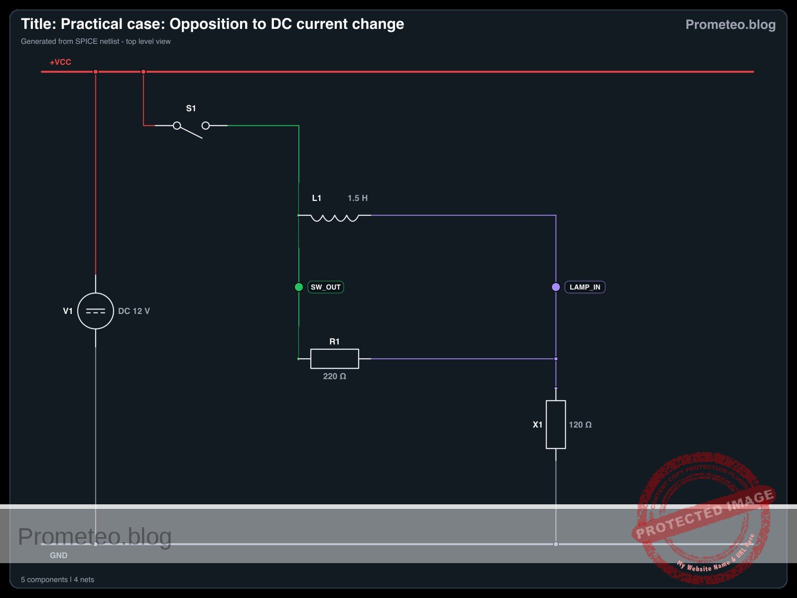
Construya el circuito utilizando las siguientes conexiones. Los nombres de los nodos (p. ej., VCC, SW_OUT) ayudan a identificar los puntos eléctricos.
- V1 (Fuente CC): Conecte el terminal positivo a
VCCy el terminal negativo a0(GND). - S1 (Interruptor): Conecte entre
VCCy el nodoSW_OUT. - L1 (Inductor): Conecte entre el nodo
SW_OUTy el nodoLAMP_IN. - R1 (Resistencia): Conecte entre el nodo
SW_OUTy el nodoLAMP_IN(esto coloca R1 en paralelo con L1). - X1 (Lámpara): Conecte entre el nodo
LAMP_INy0(GND).
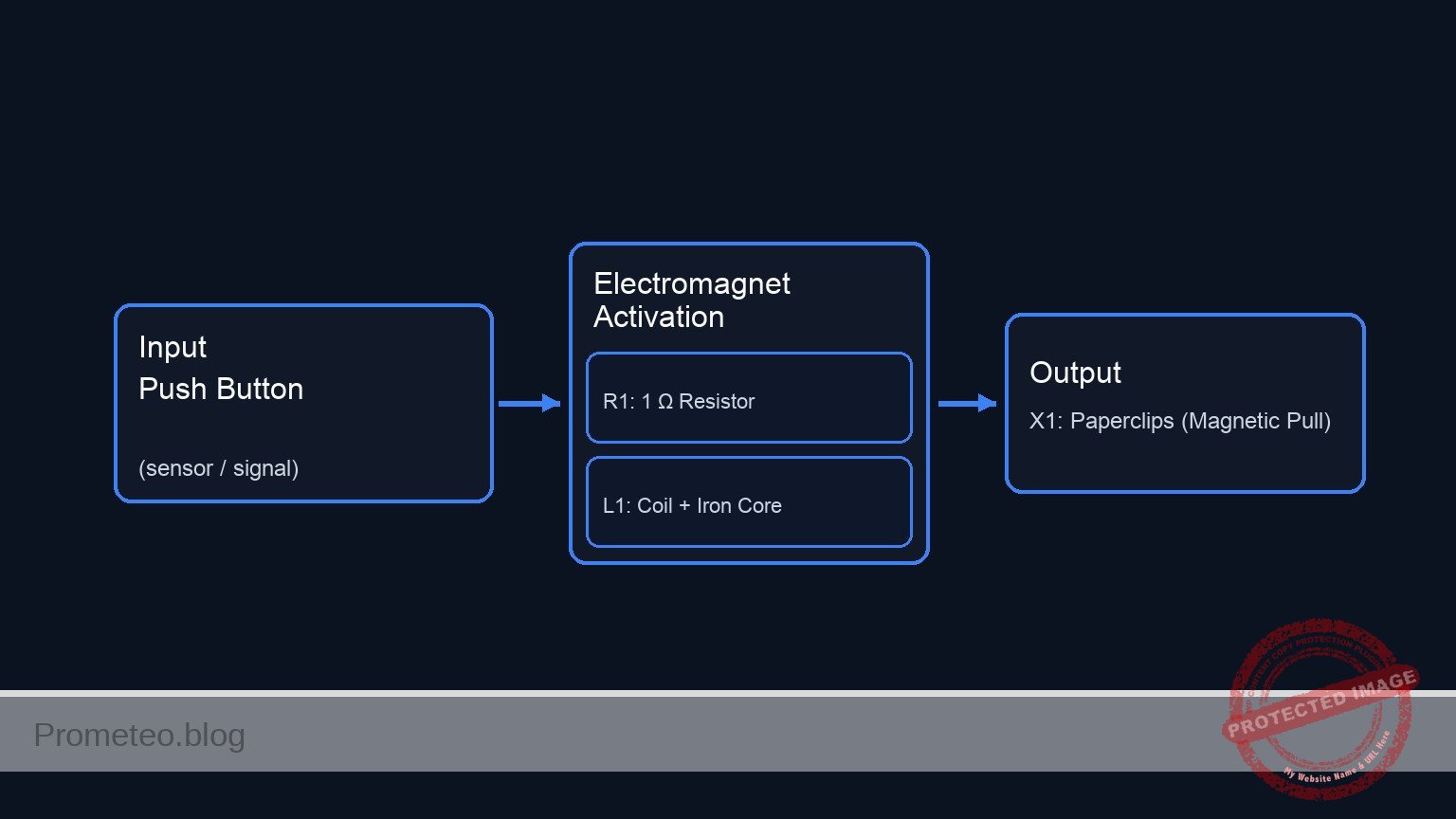
Diagrama de bloques conceptual
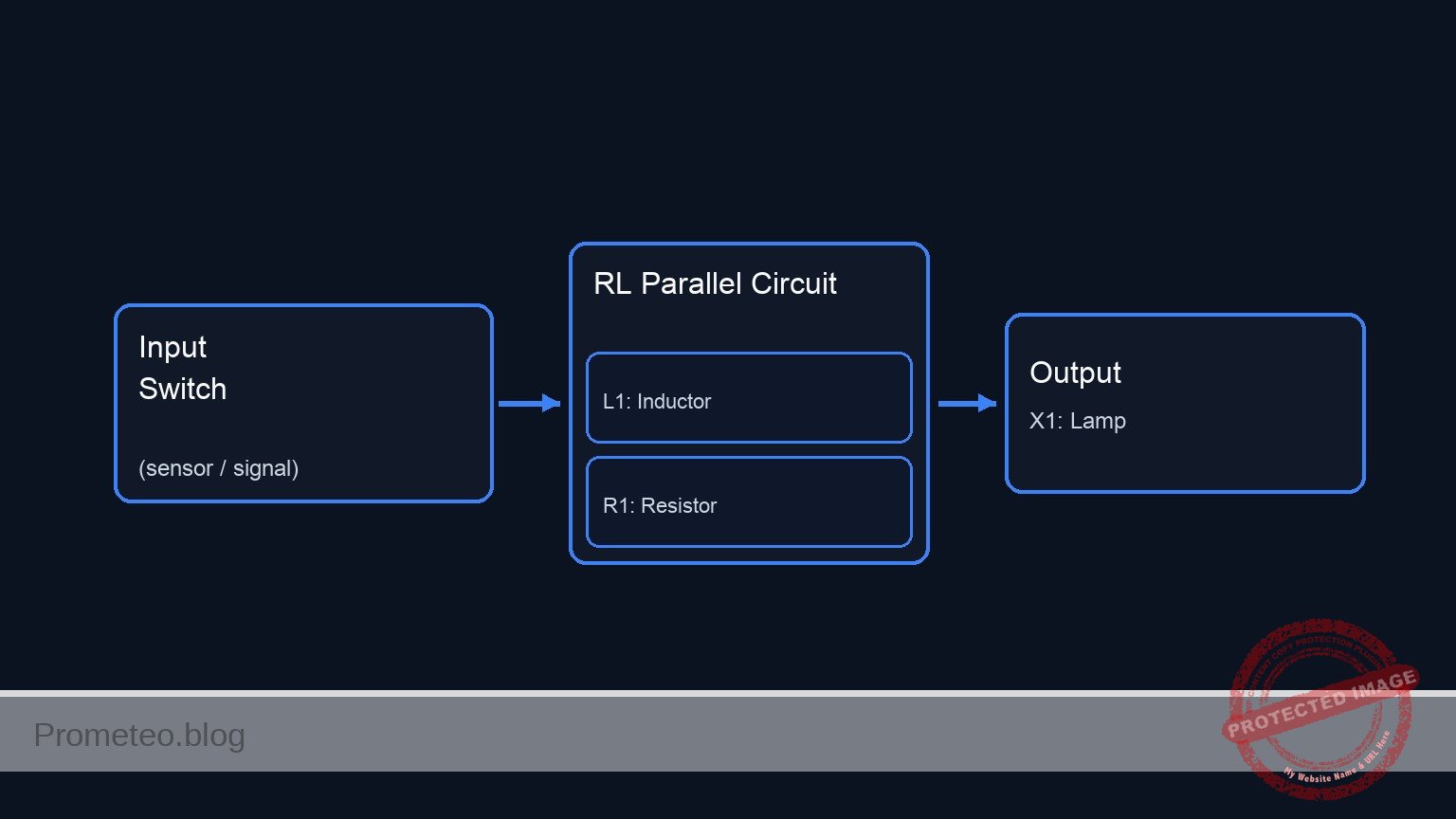
Esquemático
(Node: SW_OUT)          (Node: LAMP_IN)
                                              /--> [ L1: Inductor ] --\
[ V1: 12 V Source ] --(VCC)--> [ S1: Switch ] --                        --> [ X1: Lamp ] --> GND
                                              \--> [ R1: Resistor ] --/
Diagrama eléctrico
Mediciones y pruebas
Siga estos pasos para validar el fenómeno:
- Estado inicial: Asegúrese de que el interruptor
S1esté abierto. La lámparaX1debería estar apagada. - Observación: Mantenga la vista en la lámpara
X1. - Acción: Cierre el interruptor
S1. - Validación visual:
- Fase 1 (Instantánea): La lámpara se enciende aproximadamente al 30–50% de brillo. (La corriente fluye a través de
R1, ya queL1se opone al cambio repentino). - Fase 2 (Retardo): El brillo de la lámpara aumenta suavemente hasta el 100%. (A medida que el campo magnético en
L1se estabiliza, permite el paso total de corriente, evitandoR1).
- Fase 1 (Instantánea): La lámpara se enciende aproximadamente al 30–50% de brillo. (La corriente fluye a través de
- Medición de voltaje (Opcional): Si tiene un multímetro, coloque las sondas a través del Inductor (
SW_OUTaLAMP_IN).- En el momento del contacto, el voltaje es alto (aprox. 6–8 V).
- Después de 1–2 segundos, el voltaje cae a cerca de 0 V.
Netlist SPICE y simulación
Netlist SPICE de referencia (ngspice) — extractoNetlist SPICE completo (ngspice)
* Title: Practical case: Opposition to DC current change
.width out=256
* Description: Demonstrates inductive opposition to current change (dim-to-bright lamp effect)

* --- Power Supply ---
* 12V DC Supply
V1 VCC 0 DC 12

* --- User Interface (Switch Control) ---
* Generates a control pulse to simulate pressing the button.
* Button Press: Starts at 10ms, Duration 300ms.
V_BTN_CTRL CTRL 0 PULSE(0 5 10m 1u 1u 300m 600m)

* --- Components ---

* S1: SPST Mechanical Switch
* Connected between VCC and SW_OUT.
* Modeled as a voltage-controlled switch driven by the control pulse.
S1 VCC SW_OUT CTRL 0 SW_IDEAL

* ... (truncated in public view) ...
Copia este contenido en un archivo .cir y ejecútalo con ngspice.
* Title: Practical case: Opposition to DC current change
.width out=256
* Description: Demonstrates inductive opposition to current change (dim-to-bright lamp effect)

* --- Power Supply ---
* 12V DC Supply
V1 VCC 0 DC 12

* --- User Interface (Switch Control) ---
* Generates a control pulse to simulate pressing the button.
* Button Press: Starts at 10ms, Duration 300ms.
V_BTN_CTRL CTRL 0 PULSE(0 5 10m 1u 1u 300m 600m)

* --- Components ---

* S1: SPST Mechanical Switch
* Connected between VCC and SW_OUT.
* Modeled as a voltage-controlled switch driven by the control pulse.
S1 VCC SW_OUT CTRL 0 SW_IDEAL

* L1: 1.5H Iron-core Inductor
* Creates opposition to current change.
* Connected between SW_OUT and LAMP_IN.
L1 SW_OUT LAMP_IN 1.5

* R1: 220 Ohm Resistor
* Bypass path for visual contrast (parallel to L1).
* Connected between SW_OUT and LAMP_IN.
R1 SW_OUT LAMP_IN 220

* X1: 12V / 100mA Incandescent Lamp
* Modeled as a resistor: R = V / I = 12 / 0.1 = 120 Ohms.
* Connected between LAMP_IN and 0 (GND).
R_X1 LAMP_IN 0 120

* --- Models ---
* Ideal switch model: Low resistance when ON, High when OFF.
.model SW_IDEAL sw(vt=2.5 ron=0.01 roff=100Meg)

* --- Simulation Setup ---
* Transient analysis to capture the inductive time constant (approx 20ms).
* Simulation time: 500ms to allow full settling.
.op
.tran 1m 500m

* --- Output Directives ---
* V(SW_OUT): Input voltage to the LR network (Switch Output).
* V(LAMP_IN): Voltage across the Lamp (Visual Output).
.print tran V(SW_OUT) V(LAMP_IN) I(L1)

.end
Resultados de Simulación (Transitorio)

Show raw data table (564 rows)
Index   time            v(sw_out)       v(lamp_in)      l1#branch
0	0.000000e+00	1.439998e-05	1.439998e-05	1.199999e-07
1	1.000000e-05	1.439998e-05	1.439998e-05	1.199999e-07
2	2.000000e-05	1.439998e-05	1.439998e-05	1.199999e-07
3	4.000000e-05	1.439998e-05	1.439998e-05	1.199999e-07
4	8.000000e-05	1.439998e-05	1.439998e-05	1.199999e-07
5	1.600000e-04	1.439998e-05	1.439998e-05	1.199999e-07
6	3.200000e-04	1.439998e-05	1.439998e-05	1.199999e-07
7	6.400000e-04	1.439998e-05	1.439998e-05	1.199999e-07
8	1.280000e-03	1.439998e-05	1.439998e-05	1.199999e-07
9	2.280000e-03	1.439998e-05	1.439998e-05	1.199999e-07
10	3.280000e-03	1.439998e-05	1.439998e-05	1.199999e-07
11	4.280000e-03	1.439998e-05	1.439998e-05	1.199999e-07
12	5.280000e-03	1.439998e-05	1.439998e-05	1.199999e-07
13	6.280000e-03	1.439998e-05	1.439998e-05	1.199999e-07
14	7.280000e-03	1.439998e-05	1.439998e-05	1.199999e-07
15	8.280000e-03	1.439998e-05	1.439998e-05	1.199999e-07
16	9.280000e-03	1.439998e-05	1.439998e-05	1.199999e-07
17	1.000000e-02	1.439998e-05	1.439998e-05	1.199999e-07
18	1.000010e-02	1.439998e-05	1.439998e-05	1.199999e-07
19	1.000026e-02	1.439998e-05	1.439998e-05	1.199999e-07
20	1.000031e-02	1.439998e-05	1.439998e-05	1.199999e-07
21	1.000039e-02	1.439998e-05	1.439998e-05	1.199999e-07
22	1.000041e-02	1.439998e-05	1.439998e-05	1.199999e-07
23	1.000045e-02	1.439998e-05	1.439998e-05	1.199999e-07
... (540 more rows) ...
Errores comunes y cómo evitarlos
- Usar un LED en lugar de una lámpara incandescente: Los LED responden demasiado rápido y tienen una resistencia no lineal, haciendo que el efecto de «aumento gradual» sea muy difícil de ver. Solución: Use siempre una bombilla incandescente o un relé basado en bobina para esta demostración.
- Valor del inductor demasiado pequeño: Si usa un inductor pequeño de núcleo de aire (p. ej., 100 µH), el retardo será de microsegundos, invisible para el ojo. Solución: Use un inductor grande de núcleo de hierro, como la bobina primaria de un transformador de red (asegúrese de que esté clasificado para la corriente continua).
- Omitir la resistencia en paralelo: Sin
R1, la lámpara podría simplemente permanecer apagada por una fracción de segundo y luego encenderse de golpe, lo cual puede parecer un rebote del interruptor en lugar de una transición suave. Solución:R1proporciona un estado de referencia inmediato «tenue», haciendo que la transición a «brillante» sea mucho más obvia.
Solución de problemas
- La lámpara se enciende con brillo máximo al instante: El valor del inductor es demasiado bajo o el inductor está en cortocircuito. Verifique si está usando una bobina de núcleo de aire; cambie a una de núcleo de hierro.
- La lámpara nunca alcanza el brillo máximo: El inductor podría tener una resistencia interna de CC muy alta (cable fino). Mida la resistencia de la bobina del inductor; si es comparable a la resistencia
R1, la corriente nunca evitará completamente la resistencia. - Chispas en el interruptor al apagar: Los inductores generan voltaje de fuerza contraelectromotriz (back-EMF) cuando el circuito se interrumpe.
R1actúa como un amortiguador (snubber) aquí, pero si las chispas persisten, asegúrese de que su interruptor esté clasificado para cargas inductivas.
Posibles mejoras y extensiones
- Visualización con osciloscopio: Conecte el canal 1 de un osciloscopio a través de la Lámpara. Verá una curva exponencial ascendente, permitiéndole calcular la Constante de Tiempo (\tau = L / R).
- Retardo variable: Reemplace
R1con un potenciómetro y experimente cómo el cambio de la resistencia en paralelo afecta el brillo inicial «tenue» y la velocidad de transición percibida.
Más Casos Prácticos en Prometeo.blog
Encuentra este producto y/o libros sobre este tema en Amazon
Como afiliado de Amazon, gano con las compras que cumplan los requisitos. Si compras a través de este enlace, ayudas a mantener este proyecto.
Quiz rápido

Ingeniero Superior en Electrónica de Telecomunicaciones e Ingeniero en Informática (titulaciones oficiales en España).