Level: Medium. Implement an industrial safety circuit that activates an alarm only when both temperature and pressure sensors exceed critical safety limits.
Objective and use case
In this session, you will build a conditional logic circuit using an LM393 comparator to digitize analog sensor signals and a 74HC08 AND gate to process the safety logic.
- Industrial Boiler Safety: Prevents catastrophic failure by detecting when a boiler is both overheating and over-pressurized.
- Hydraulic Systems: Monitors fluid states to prevent pump damage or pipe bursts during high-stress operations.
- Chemical Reactor Monitoring: Ensures reaction conditions remain within safe zones, triggering emergency cooling only when multiple critical variables spike.
Expected outcome:
* Safe State: LED remains OFF if only one or neither variable exceeds the limit.
* Critical State: Red LED turns ON (Logic High) only when Temp > Limit AND Pressure > Limit.
* Logic Level: The 74HC08 output shifts from ~0V to ~5V.
* Target Audience: Engineering students and hobbyists familiar with operational amplifiers/comparators and basic digital logic.
Materials
- V1: 5 V DC supply
- U1: 74HC08, function: Quad 2-Input AND Gate
- U2: LM393, function: Dual Differential Comparator
- RT1: 10 kΩ NTC thermistor, function: Temperature sensor
- R1: 10 kΩ resistor, function: Voltage divider bottom for NTC
- RP1: 10 kΩ linear potentiometer, function: Pressure sensor simulator
- RP2: 10 kΩ potentiometer, function: Temperature reference threshold (V_REF_T)
- RP3: 10 kΩ potentiometer, function: Pressure reference threshold (V_REF_P)
- R2: 4.7 kΩ resistor, function: Pull-up for Comparator A output (required for LM393)
- R3: 4.7 kΩ resistor, function: Pull-up for Comparator B output (required for LM393)
- R4: 330 Ω resistor, function: LED current limiting
- D1: Red LED, function: Critical Alert indicator
Pin-out of the IC used
Selected Chip: 74HC08 (Quad 2-Input AND Gate)
| Pin | Name | Logic function | Connection in this case |
|---|---|---|---|
| 1 | 1A | Input A | Connected to Temperature Comparator Output |
| 2 | 1B | Input B | Connected to Pressure Comparator Output |
| 3 | 1Y | Output | Connected to LED (via R4) |
| 7 | GND | Ground | Connected to 0V supply rail |
| 14 | VCC | Power Supply | Connected to +5V supply rail |
Note: The LM393 Comparator is also used but the logic decision happens in the 74HC08.
Wiring guide
Construct the circuit using the following node connections:
- Power Rail: Connect
V1positive terminal to nodeVCCand negative terminal to node0(GND). Connect pin 14 ofU1and pin 8 ofU2toVCC. Connect pin 7 ofU1and pin 4 ofU2to0. - Temperature Sensor Input (
V_TEMP): ConnectRT1betweenVCCandV_TEMP. ConnectR1betweenV_TEMPand0. (As Temp rises, resistance drops,V_TEMPrises). - Pressure Sensor Input (
V_PRESS): Connect the wiper ofRP1to nodeV_PRESS. Connect the outer legs ofRP1toVCCand0. - Reference Thresholds: Connect the wiper of
RP2to nodeV_REF_T(Temp Limit). Connect the wiper ofRP3to nodeV_REF_P(Pressure Limit). - Comparator Stage (Digitization):
- Connect
V_TEMPtoU2pin 3 (Non-inverting input A). - Connect
V_REF_TtoU2pin 2 (Inverting input A). - Connect
V_PRESStoU2pin 5 (Non-inverting input B). - Connect
V_REF_PtoU2pin 6 (Inverting input B).
- Connect
- Comparator Outputs (
LOGIC_TandLOGIC_P):- Connect
U2pin 1 (Output A) to nodeLOGIC_T. Connect pull-up resistorR2betweenLOGIC_TandVCC. - Connect
U2pin 7 (Output B) to nodeLOGIC_P. Connect pull-up resistorR3betweenLOGIC_PandVCC.
- Connect
- Logic Gate:
- Connect
LOGIC_TtoU1pin 1 (Input 1A). - Connect
LOGIC_PtoU1pin 2 (Input 1B). - Connect
U1pin 3 (Output 1Y) to nodeALERT.
- Connect
- Indicator: Connect
R4betweenALERTand the anode ofD1. Connect the cathode ofD1to0.
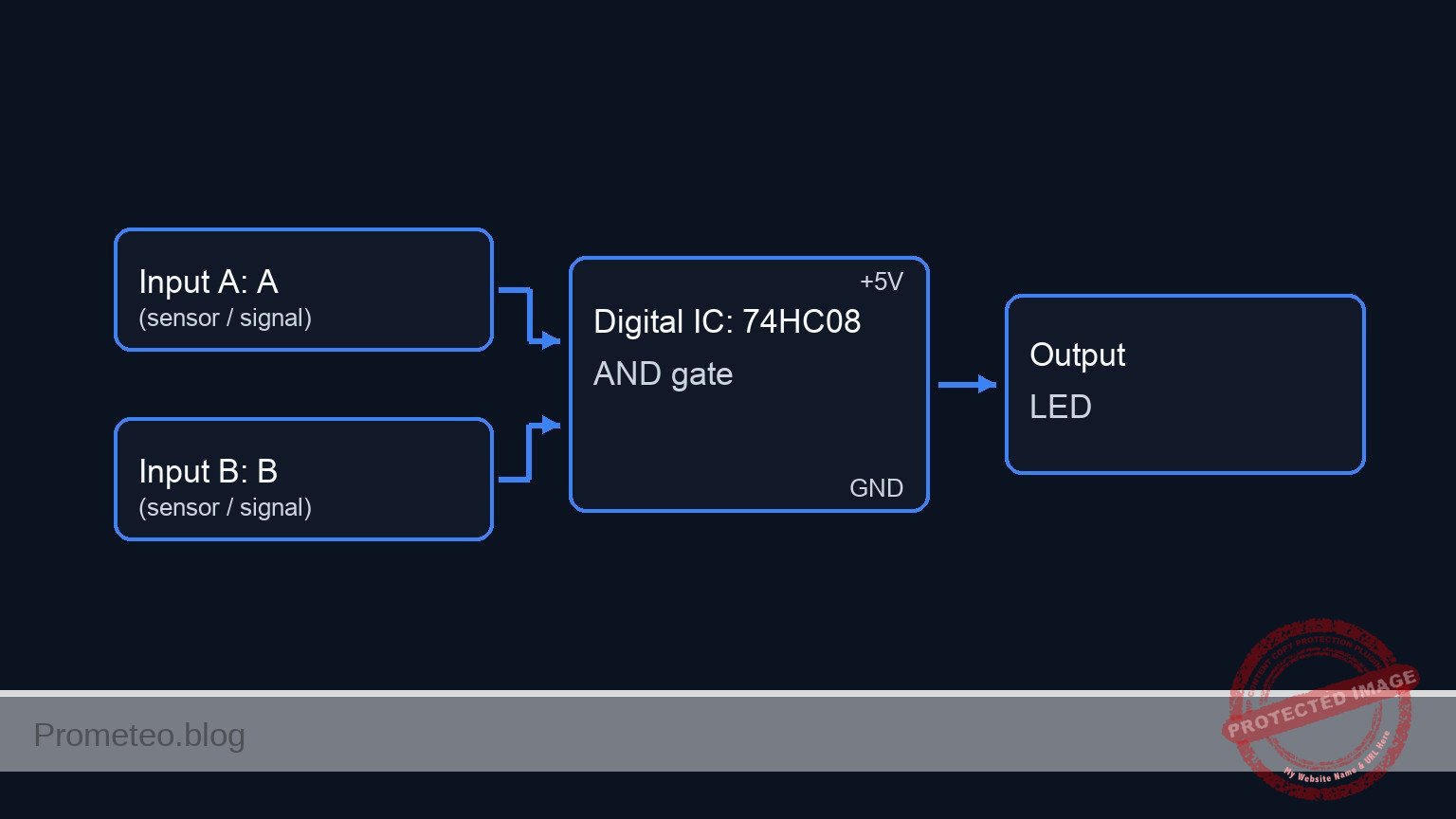
Conceptual block diagram
Schematic
[ ANALOG INPUTS ]                  [ COMPARATORS ]                  [ LOGIC GATE ]               [ OUTPUT ]

[ Temp Sensor (RT1/R1) ] --(V_TEMP)---->+------------------+
                                        | U2: Comparator A |
                                        | (LM393)          |--(LOGIC_T)-->+
[ Temp Ref Pot (RP2)   ] --(V_REF_T)--->| w/ Pull-up R2    |              |
                                        +------------------+              |
                                                                          v
                                                                   +----------------+
                                                                   | U1: AND Gate   |
                                                                   | (74HC08)       |--(ALERT)--> [ Resistor R4 ] --> [ LED D1 ] --> GND
                                                                   +----------------+
                                                                          ^
                                        +------------------+              |
[ Press Sensor (RP1)   ] --(V_PRESS)--->| U2: Comparator B |              |
                                        | (LM393)          |--(LOGIC_P)-->+
[ Press Ref Pot (RP3)  ] --(V_REF_P)--->| w/ Pull-up R3    |
                                        +------------------+
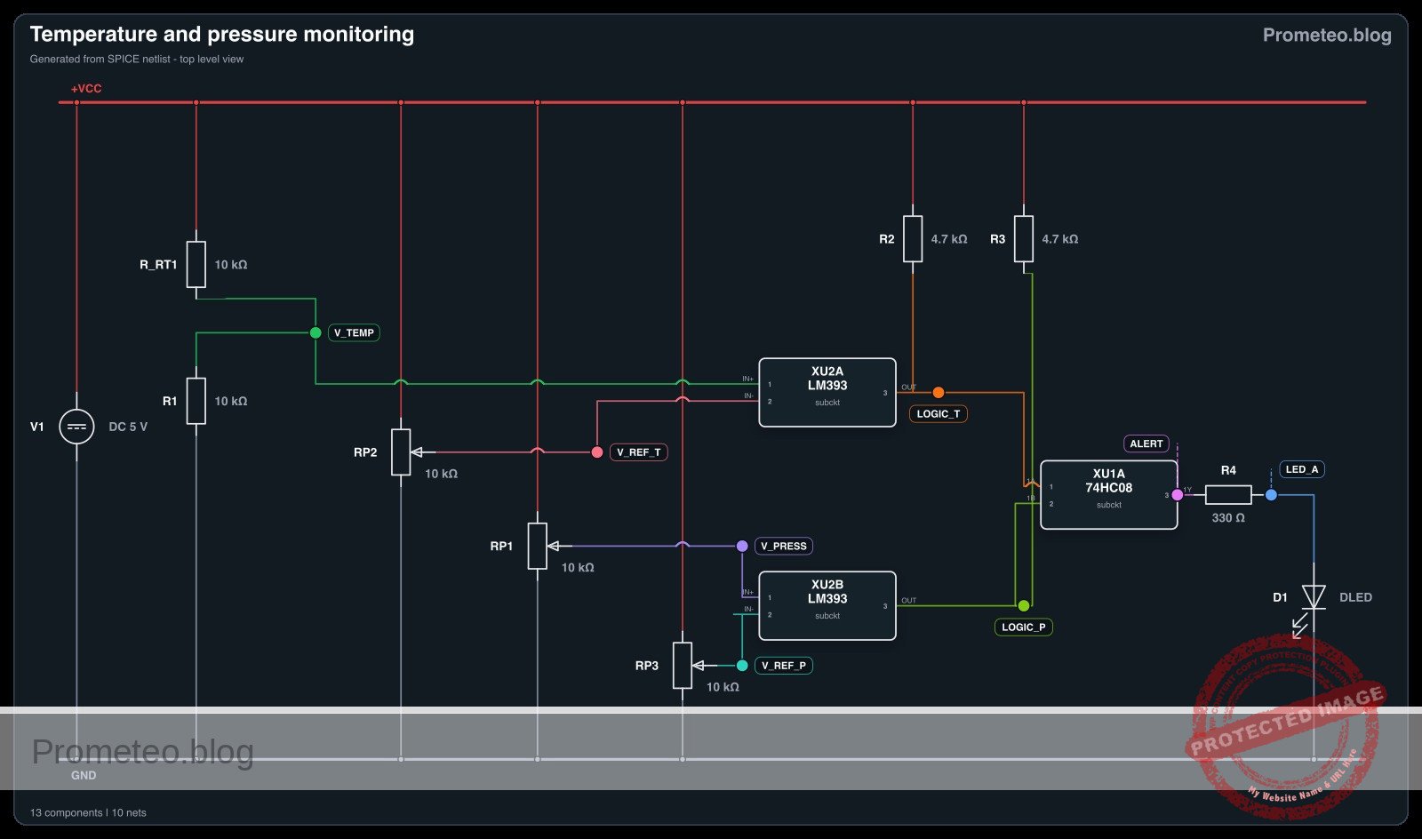
Electrical diagram
Truth table
This table represents the logic states at the inputs of the 74HC08 (after the comparator stage) and the final output.
| Sensor: Temperature | Sensor: Pressure | Input 1A (Temp Alert) | Input 1B (Press Alert) | Output 1Y (System Alarm) | LED State |
|---|---|---|---|---|---|
| Low (< Ref) | Low (< Ref) | 0 | 0 | 0 | OFF |
| Low (< Ref) | High (> Ref) | 0 | 1 | 0 | OFF |
| High (> Ref) | Low (< Ref) | 1 | 0 | 0 | OFF |
| High (> Ref) | High (> Ref) | 1 | 1 | 1 | ON |
Measurements and tests
- Calibrate Thresholds: Use a voltmeter to set
V_REF_T(atRP2wiper) to 3.0V andV_REF_P(atRP3wiper) to 3.0V. - Test Temperature Logic: Heat
RT1(or simulate by shorting R1 slightly) untilV_TEMP> 3.0V. MeasureLOGIC_T; it should be High (~5V). Verify LED is OFF (since Pressure is Low). - Test Pressure Logic: Turn
RP1untilV_PRESS> 3.0V. MeasureLOGIC_P; it should be High (~5V). - System Alert Test: Create a condition where
V_TEMP> 3.0V ANDV_PRESS> 3.0V simultaneously.- Measure Voltage at
ALERT(U1 Pin 3): Expected ~5V. - Visual: The Red LED
D1must turn ON.
- Measure Voltage at
SPICE netlist and simulation
Reference SPICE Netlist (ngspice) — excerptFull SPICE netlist (ngspice)
* Practical case: Temperature and Pressure Monitoring

* --- Power Supply ---
* V1: 5 V DC supply
V1 VCC 0 DC 5

* --- Sensors and Inputs ---
* Temperature Sensor (RT1 NTC + R1 Divider)
* RT1: 10 kΩ NTC thermistor (Modeled as R_RT1)
* Connected between VCC and V_TEMP
R_RT1 VCC V_TEMP 10k
* R1: 10 kΩ resistor (Voltage divider bottom)
* Connected between V_TEMP and 0 (GND)
R1 V_TEMP 0 10k

* Pressure Sensor (RP1 Potentiometer)
* RP1: 10 kΩ linear potentiometer
* Modeled as two resistors (Top/Bot) representing the wiper position.
* Outer legs to VCC and 0, wiper to V_PRESS.
R_RP1_TOP VCC V_PRESS 5k
R_RP1_BOT V_PRESS 0 5k

* --- Dynamic Stimuli (Simulation) ---
* These voltage sources drive the sensor nodes to simulate physical changes
* over time, verifying the logic thresholds (sweeping 1V to 4V).
* They effectively override the static resistor dividers for transient analysis.
V_TEMP_STIM V_TEMP 0 PULSE(1 4 0.5m 100u 100u 1m 3m)
V_PRESS_STIM V_PRESS 0 PULSE(1 4 1m 100u 100u 1.5m 4m)

* --- Reference Thresholds ---
* ... (truncated in public view) ...
Copy this content into a .cir file and run with ngspice.
* Practical case: Temperature and Pressure Monitoring

* --- Power Supply ---
* V1: 5 V DC supply
V1 VCC 0 DC 5

* --- Sensors and Inputs ---
* Temperature Sensor (RT1 NTC + R1 Divider)
* RT1: 10 kΩ NTC thermistor (Modeled as R_RT1)
* Connected between VCC and V_TEMP
R_RT1 VCC V_TEMP 10k
* R1: 10 kΩ resistor (Voltage divider bottom)
* Connected between V_TEMP and 0 (GND)
R1 V_TEMP 0 10k

* Pressure Sensor (RP1 Potentiometer)
* RP1: 10 kΩ linear potentiometer
* Modeled as two resistors (Top/Bot) representing the wiper position.
* Outer legs to VCC and 0, wiper to V_PRESS.
R_RP1_TOP VCC V_PRESS 5k
R_RP1_BOT V_PRESS 0 5k

* --- Dynamic Stimuli (Simulation) ---
* These voltage sources drive the sensor nodes to simulate physical changes
* over time, verifying the logic thresholds (sweeping 1V to 4V).
* They effectively override the static resistor dividers for transient analysis.
V_TEMP_STIM V_TEMP 0 PULSE(1 4 0.5m 100u 100u 1m 3m)
V_PRESS_STIM V_PRESS 0 PULSE(1 4 1m 100u 100u 1.5m 4m)

* --- Reference Thresholds ---
* RP2: 10 kΩ potentiometer (Temperature Reference)
* Configured as divider, wiper to V_REF_T. Set to ~2.5V.
R_RP2_TOP VCC V_REF_T 5k
R_RP2_BOT V_REF_T 0 5k

* RP3: 10 kΩ potentiometer (Pressure Reference)
* Configured as divider, wiper to V_REF_P. Set to ~2.5V.
R_RP3_TOP VCC V_REF_P 5k
R_RP3_BOT V_REF_P 0 5k

* --- Comparator Stage (U2: LM393) ---
* U2: Dual Differential Comparator
* Connections based on Wiring Guide:
*   Comp A (Temp): In+ (3)=V_TEMP, In- (2)=V_REF_T, Out (1)=LOGIC_T
*   Comp B (Press): In+ (5)=V_PRESS, In- (6)=V_REF_P, Out (7)=LOGIC_P
*   Power: VCC (8), GND (4)
XU2 LOGIC_T V_REF_T V_TEMP 0 V_PRESS V_REF_P LOGIC_P VCC LM393

* Pull-up resistors (Required for Open Collector Outputs)
* R2: 4.7 kΩ pull-up for Comparator A
R2 VCC LOGIC_T 4.7k
* R3: 4.7 kΩ pull-up for Comparator B
R3 VCC LOGIC_P 4.7k

* --- Logic Stage (U1: 74HC08) ---
* U1: Quad 2-Input AND Gate
* Connections:
*   Gate 1: Input 1A (1)=LOGIC_T, Input 1B (2)=LOGIC_P, Output 1Y (3)=ALERT
*   Power: VCC (14), GND (7)
*   Unused inputs (4,5,9,10,12,13) connected to 0 (GND) to prevent floating.
XU1 LOGIC_T LOGIC_P ALERT 0 0 0 0 0 0 0 0 0 0 VCC 74HC08

* --- Indicator ---
* R4: 330 Ω resistor (LED current limiting)
R4 ALERT LED_A 330
* D1: Red LED (Cathode to GND)
D1 LED_A 0 DLED

* --- Models and Subcircuits ---

* LED Model
.model DLED D(IS=1e-14 N=1.7 RS=10)

* LM393 Subcircuit (Behavioral Open Collector)
.subckt LM393 1 2 3 4 5 6 7 8
* Pinout: 1=OutA, 2=InA-, 3=InA+, 4=GND, 5=InB+, 6=InB-, 7=OutB, 8=VCC
* Logic: If In+ > In-, Output is High-Z (Pull-up High).
*        If In+ < In-, Output is Low (GND).
* Implementation uses Voltage Controlled Switch to GND.
* Control V = In(-) - In(+). If V > 0 (In- > In+), Switch Closed (Low).
B_A_CTRL 10 0 V = V(2) - V(3)
S_A 1 4 10 0 SW_OC
B_B_CTRL 20 0 V = V(6) - V(5)
S_B 7 4 20 0 SW_OC
.model SW_OC SW(Vt=0 Vh=1m Ron=10 Roff=100Meg)
.ends LM393

* 74HC08 Subcircuit (Behavioral AND Gate)
.subckt 74HC08 1 2 3 4 5 6 7 8 9 10 11 12 13 14
* Pinout: 1=1A, 2=1B, 3=1Y, 7=GND, 14=VCC ...
* Gate 1 Logic: Output High (VCC) if V(1)>2.5 and V(2)>2.5
B_Y1 3 7 V = V(14) * (1 / (1 + exp(-50*(V(1)-2.5)))) * (1 / (1 + exp(-50*(V(2)-2.5))))
.ends 74HC08

* --- Simulation Directives ---
.tran 10u 5ms
.print tran V(V_TEMP) V(V_PRESS) V(LOGIC_T) V(LOGIC_P) V(ALERT)

.end
Simulation Results (Transient Analysis)

Show raw data table (1124 rows)
Index   time            v(v_temp)       v(v_press)      v(logic_t)
0	0.000000e+00	1.000000e+00	1.000000e+00	1.061571e-02
1	1.000000e-07	1.000000e+00	1.000000e+00	1.061571e-02
2	2.000000e-07	1.000000e+00	1.000000e+00	1.061571e-02
3	4.000000e-07	1.000000e+00	1.000000e+00	1.061571e-02
4	8.000000e-07	1.000000e+00	1.000000e+00	1.061571e-02
5	1.600000e-06	1.000000e+00	1.000000e+00	1.061571e-02
6	3.200000e-06	1.000000e+00	1.000000e+00	1.061571e-02
7	6.400000e-06	1.000000e+00	1.000000e+00	1.061571e-02
8	1.280000e-05	1.000000e+00	1.000000e+00	1.061571e-02
9	2.280000e-05	1.000000e+00	1.000000e+00	1.061571e-02
10	3.280000e-05	1.000000e+00	1.000000e+00	1.061571e-02
11	4.280000e-05	1.000000e+00	1.000000e+00	1.061571e-02
12	5.280000e-05	1.000000e+00	1.000000e+00	1.061571e-02
13	6.280000e-05	1.000000e+00	1.000000e+00	1.061571e-02
14	7.280000e-05	1.000000e+00	1.000000e+00	1.061571e-02
15	8.280000e-05	1.000000e+00	1.000000e+00	1.061571e-02
16	9.280000e-05	1.000000e+00	1.000000e+00	1.061571e-02
17	1.028000e-04	1.000000e+00	1.000000e+00	1.061571e-02
18	1.128000e-04	1.000000e+00	1.000000e+00	1.061571e-02
19	1.228000e-04	1.000000e+00	1.000000e+00	1.061571e-02
20	1.328000e-04	1.000000e+00	1.000000e+00	1.061571e-02
21	1.428000e-04	1.000000e+00	1.000000e+00	1.061571e-02
22	1.528000e-04	1.000000e+00	1.000000e+00	1.061571e-02
23	1.628000e-04	1.000000e+00	1.000000e+00	1.061571e-02
... (1100 more rows) ...
Common mistakes and how to avoid them
- Missing Pull-up Resistors on Comparators: The LM393 has open-collector outputs. If you omit
R2andR3, the inputs to the 74HC08 will float or remain low, preventing the circuit from working. Solution: Always install pull-ups (4.7kΩ to 10kΩ) from the output pin to VCC. - Incorrect NTC Wiring: Connecting the NTC to ground and the fixed resistor to VCC creates a voltage that drops as temperature rises. Solution: Connect the NTC to VCC and the fixed resistor to Ground to ensure voltage increases with temperature, matching the non-inverting comparator logic.
- Floating Inputs on 74HC08: Leaving unused inputs on the logic chip connected to nothing can cause noise and higher power consumption. Solution: Connect unused inputs (e.g., pins 4, 5, 9, 10, 12, 13) to GND.
Troubleshooting
- LED never turns ON: Check if
R2orR3are missing. Without them, the AND gate inputs see Logic 0. Verify the orientation of the LED. - LED is always ON: Check
RP2andRP3. If the reference voltage is set to 0V, the sensors will always appear «High» relative to the reference. - Erratic/Flickering LED: The voltage at the comparator inputs might be hovering exactly at the threshold. This creates noise. Adding a hysteresis feedback resistor can solve this, but ensuring clean power connections usually suffices for basic tests.
Possible improvements and extensions
- Add Hysteresis: Connect a high-value resistor (e.g., 100kΩ) between the comparator output and the non-inverting input. This prevents the «chattering» effect when sensor values hover near the threshold.
- Audible Alarm: Connect a buzzer with a transistor driver (like a 2N2222) to the output of the 74HC08 alongside the LED for an audible warning in a noisy industrial environment.
More Practical Cases on Prometeo.blog
Find this product and/or books on this topic on Amazon
As an Amazon Associate, I earn from qualifying purchases. If you buy through this link, you help keep this project running.
Quick Quiz

Telecommunications Electronics Engineer and Computer Engineer (official degrees in Spain).