

Level: Medium. Design a safety interlock circuit that activates a conveyor belt only when the operator is present and a load is detected.
Objective and use case
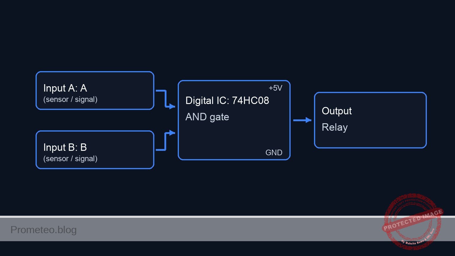
In this practical case, you will build a safety logic circuit using a 74HC08 AND gate to control the activation of a DC motor via a relay. The system ensures the conveyor belt only runs when two distinct safety conditions are met simultaneously.
- Real-world application: Industrial safety interlocks preventing machinery from starting without an operator at the controls.
- Efficiency: Automated energy saving by ensuring the belt only runs when a product (load) is actually present on the line.
- Machine protection: Preventing «dry runs» that might wear out mechanical components unnecessarily.
Expected outcome:
* Logic Output: The 74HC08 output pin goes HIGH (approx. 5V) only when both inputs are HIGH.
* Motor State: The DC motor turns ON only when the Operator Button is held AND the Optical Sensor detects an object.
* Current Drive: A transistor amplifies the weak logic signal to switch the 5V relay coil.
* Target Audience: Engineering students and maintenance technicians (Medium level).
Materials
- V1: 5V DC Power Supply, function: Main circuit power.
- U1: 74HC08 Quad 2-Input AND Gate, function: Safety logic processing.
- S1: Push button (Normally Open), function: Simulates «Operator Presence».
- S2: Switch (SPST) or Phototransistor module, function: Simulates «Optical Load Sensor» (Active High).
- R1: 10 kΩ resistor, function: Pull-down for Operator input (S1).
- R2: 10 kΩ resistor, function: Pull-down for Sensor input (S2).
- R3: 1 kΩ resistor, function: Base current limiting for Q1.
- Q1: 2N2222 NPN Transistor, function: Relay driver switch.
- D1: 1N4007 Diode, function: Flyback protection for the relay coil.
- K1: 5V Relay (SPDT), function: High-current switch for the motor.
- M1: 5V DC Motor, function: Conveyor belt drive.
- C1: 100 nF capacitor, function: Decoupling for U1 power supply.
Pin-out of the IC used
Chip: 74HC08 (Quad 2-Input AND Gate)
| Pin | Name | Logic function | Connection in this case |
|---|---|---|---|
| 1 | 1A | Input A | Connected to Operator Button (S1) |
| 2 | 1B | Input B | Connected to Optical Sensor (S2) |
| 3 | 1Y | Output | Connected to Transistor Base Resistor (R3) |
| 7 | GND | Ground | Connected to 0V (GND) |
| 14 | VCC | Power | Connected to +5V (VCC) |
Note: Pins 4-6 and 8-13 are unused in this single-gate application and should technically be tied to GND in a permanent noise-sensitive environment, but are left open for this basic prototype.
Wiring guide
Use the following nodes for your connections: VCC, 0 (Ground), OP_SIGNAL, LOAD_SIGNAL, LOGIC_OUT.
- Power: Connect
VCCto the positive rail of V1 and0to the negative rail. - Input S1 (Operator): Connect one side of S1 to
VCC. Connect the other side to nodeOP_SIGNAL. - Pull-down R1: Connect R1 between
OP_SIGNALand0. - Input S2 (Sensor): Connect one side of S2 to
VCC. Connect the other side to nodeLOAD_SIGNAL. - Pull-down R2: Connect R2 between
LOAD_SIGNALand0. - Logic U1:
- Connect U1 Pin 14 to
VCCand Pin 7 to0. - Connect C1 between
VCCand0near U1. - Connect
OP_SIGNALto U1 Pin 1 (Input 1A). - Connect
LOAD_SIGNALto U1 Pin 2 (Input 1B). - Connect U1 Pin 3 (Output 1Y) to node
LOGIC_OUT.
- Connect U1 Pin 14 to
- Driver Stage:
- Connect R3 between
LOGIC_OUTand the Base of Q1. - Connect the Emitter of Q1 to
0. - Connect the Collector of Q1 to the Relay coil (K1 pin 1).
- Connect R3 between
- Relay & Motor:
- Connect the other side of the Relay coil (K1 pin 2) to
VCC. - Connect D1 across the Relay coil (Cathode to
VCC, Anode to Q1 Collector). - Connect Relay Common (COM) to
VCC. - Connect Relay Normally Open (NO) to the positive terminal of M1.
- Connect the negative terminal of M1 to
0.
- Connect the other side of the Relay coil (K1 pin 2) to
Conceptual block diagram
Schematic
[ INPUTS ]                       [ LOGIC ]                        [ OUTPUT STAGE ]

    (VCC)                                                                    (VCC)
      |                                                                        |
    [ S1: Operator ]--(OP_SIGNAL)-->+-------------+                       +----+----+
      |                             |  Pin 1 (A)  |                       | K1 Coil | (Parallel D1)
    [ R1: 10k ]                     |             |                       +----+----+
      |                             |   74HC08    |                            ^
    (GND)                           |     U1      |                            |
                                    |             |--(Pin 3)-->[ R3: 1k ]-->[ Q1: NPN ]
    (VCC)                           |             |          (LOGIC_OUT)       |
      |                             |             |                            v
    [ S2: Sensor ]--(LOAD_SIGNAL)-->|  Pin 2 (B)  |                          (GND)
      |                             |             |
    [ R2: 10k ]                     +-------------+                          (VCC)
      |                                    |                                   |
    (GND)                               [ C1 ]                           [ K1 Switch ]
                                           |                                   |
                                         (GND)                                 v
                                                                         [ M1: Motor ]
                                                                               |
                                                                             (GND)
Truth table
This table represents the logic states required to start the motor.
| Operator (S1) | Load Detected (S2) | U1 Output (Pin 3) | Transistor Q1 | Motor State |
|---|---|---|---|---|
| Low (0) | Low (0) | Low (0) | OFF (Cut-off) | STOP |
| Low (0) | High (1) | Low (0) | OFF (Cut-off) | STOP |
| High (1) | Low (0) | Low (0) | OFF (Cut-off) | STOP |
| High (1) | High (1) | High (1) | ON (Sat) | RUN |
Measurements and tests
Validate the circuit operation using a multimeter:
- Input Verification: Measure voltage at
OP_SIGNALrelative to GND. It should be 0V when S1 is open and 5V when pressed. Repeat forLOAD_SIGNAL(S2). - Logic Output: With S1 and S2 active, measure voltage at
LOGIC_OUT. It should be approximately equal to VCC (Logic High). If either is released, it should drop to ~0V. - Base Current (I_b): Set your multimeter to Ammeter mode. Place it in series with R3. When logic is High, you should measure approximately 4.3mA (calculated as $(5V – 0.7V) / 1000\Omega$). This confirms the transistor is being driven hard enough to saturate.
- Relay Actuation: Listen for the «click» of the relay when both inputs are active. Measure voltage across the Motor terminals; it should read 5V.
SPICE netlist and simulation
Reference SPICE Netlist (ngspice) — excerptFull SPICE netlist (ngspice)
* Title: Practical case: Conveyor belt start system

* --- Power Supply ---
* V1: 5V DC Power Supply
V1 VCC 0 DC 5

* --- Input S1: Operator Presence ---
* Component: Push button (NO) modeled as Voltage-Controlled Switch
* Wiring: VCC -> S1 -> OP_SIGNAL -> R1 -> 0
S1 VCC OP_SIGNAL CTRL_OP 0 SW_BTN
R1 OP_SIGNAL 0 10k
* Stimulus: Simulate button press (High) from t=1ms to t=4ms
V_ACT_S1 CTRL_OP 0 PULSE(0 5 1m 10u 10u 3m 10m)

* --- Input S2: Optical Load Sensor ---
* Component: Switch/Sensor modeled as Voltage-Controlled Switch
* Wiring: VCC -> S2 -> LOAD_SIGNAL -> R2 -> 0
S2 VCC LOAD_SIGNAL CTRL_LOAD 0 SW_BTN
R2 LOAD_SIGNAL 0 10k
* Stimulus: Simulate sensor active (High) from t=2ms to t=5ms
V_ACT_S2 CTRL_LOAD 0 PULSE(0 5 2m 10u 10u 3m 10m)

* --- Logic U1: 74HC08 Quad AND Gate ---
* Wiring: Pin 14=VCC, Pin 7=0, Pin 1=OP_SIGNAL, Pin 2=LOAD_SIGNAL, Pin 3=LOGIC_OUT
* Decoupling Capacitor C1
C1 VCC 0 100n
* Instantiation of Logic Gate Subcircuit
XU1 OP_SIGNAL LOAD_SIGNAL LOGIC_OUT VCC 0 74HC08_GATE

* --- Driver Stage ---
* ... (truncated in public view) ...
Copy this content into a .cir file and run with ngspice.
* Title: Practical case: Conveyor belt start system

* --- Power Supply ---
* V1: 5V DC Power Supply
V1 VCC 0 DC 5

* --- Input S1: Operator Presence ---
* Component: Push button (NO) modeled as Voltage-Controlled Switch
* Wiring: VCC -> S1 -> OP_SIGNAL -> R1 -> 0
S1 VCC OP_SIGNAL CTRL_OP 0 SW_BTN
R1 OP_SIGNAL 0 10k
* Stimulus: Simulate button press (High) from t=1ms to t=4ms
V_ACT_S1 CTRL_OP 0 PULSE(0 5 1m 10u 10u 3m 10m)

* --- Input S2: Optical Load Sensor ---
* Component: Switch/Sensor modeled as Voltage-Controlled Switch
* Wiring: VCC -> S2 -> LOAD_SIGNAL -> R2 -> 0
S2 VCC LOAD_SIGNAL CTRL_LOAD 0 SW_BTN
R2 LOAD_SIGNAL 0 10k
* Stimulus: Simulate sensor active (High) from t=2ms to t=5ms
V_ACT_S2 CTRL_LOAD 0 PULSE(0 5 2m 10u 10u 3m 10m)

* --- Logic U1: 74HC08 Quad AND Gate ---
* Wiring: Pin 14=VCC, Pin 7=0, Pin 1=OP_SIGNAL, Pin 2=LOAD_SIGNAL, Pin 3=LOGIC_OUT
* Decoupling Capacitor C1
C1 VCC 0 100n
* Instantiation of Logic Gate Subcircuit
XU1 OP_SIGNAL LOAD_SIGNAL LOGIC_OUT VCC 0 74HC08_GATE

* --- Driver Stage ---
* Wiring: LOGIC_OUT -> R3 -> Q1 Base
R3 LOGIC_OUT Q1_BASE 1k
* Wiring: Q1 Collector -> Relay Coil, Emitter -> 0
Q1 RELAY_COIL_LOW Q1_BASE 0 2N2222MOD

* --- Relay K1 ---
* Wiring: VCC -> Coil -> Q1 Collector (RELAY_COIL_LOW)
* Coil modeled as Inductance + Resistance
L_K1 VCC K1_INT 10m
R_K1 K1_INT RELAY_COIL_LOW 100

* Flyback Diode D1
* Wiring: Cathode to VCC, Anode to Q1 Collector
D1 RELAY_COIL_LOW VCC 1N4007MOD

* Relay Contact (Switch)
* Wiring: COM (VCC) -> NO (MOTOR_POS)
* Controlled by voltage across the coil: V(VCC) - V(RELAY_COIL_LOW)
* FIXED: Connected negative control node to Ground (0) to fix Singular Matrix error
E_K1_SENSE K1_CTRL_P 0 VOL = 'V(VCC) - V(RELAY_COIL_LOW)'
S_K1 VCC MOTOR_POS K1_CTRL_P 0 SW_RELAY

* --- Motor M1 ---
* Wiring: MOTOR_POS -> Motor -> 0
* Modeled as an inductive load
R_M1 MOTOR_POS M1_INT 10
L_M1 M1_INT 0 1m

* --- Models & Subcircuits ---

* Button/Sensor Switch Model
.model SW_BTN SW(Vt=2.5 Vh=0.1 Ron=0.1 Roff=10Meg)

* Relay Contact Switch Model (Activates when coil voltage > 3.5V)
.model SW_RELAY SW(Vt=3.5 Vh=0.5 Ron=0.05 Roff=100Meg)

* Transistor Model
.model 2N2222MOD NPN(IS=1E-14 BF=200 VAF=100 IKF=0.3 XTB=1.5 BR=3 CJC=8p CJE=25p)

* Diode Model
.model 1N4007MOD D(IS=7n RS=0.03 N=1.2 BV=1000 IBV=5u CJO=10p TT=100n)

* 74HC08 AND Gate Behavioral Model
* Pins: A B Y VCC GND
.subckt 74HC08_GATE A B Y VCC GND
* Continuous Sigmoid function for convergence: 5V * sigmoid(A) * sigmoid(B)
B_AND Y GND V = V(VCC) * (1 / (1 + exp(-50*(V(A)-2.5)))) * (1 / (1 + exp(-50*(V(B)-2.5))))
.ends

* --- Simulation Directives ---
.op
* Transient analysis: 10us step, 8ms total time
.tran 10u 8m
* Print required voltages
.print tran V(OP_SIGNAL) V(LOAD_SIGNAL) V(LOGIC_OUT) V(RELAY_COIL_LOW) V(MOTOR_POS)

.end
Simulation Results (Transient Analysis)

Show raw data table (7686 rows)
Index   time            v(op_signal)    v(load_signal)  v(logic_out)
0	0.000000e+00	4.995005e-03	4.995005e-03	2.199277e-108
1	1.000000e-07	4.995005e-03	4.995005e-03	2.199277e-108
2	2.000000e-07	4.995005e-03	4.995005e-03	2.199277e-108
3	4.000000e-07	4.995005e-03	4.995005e-03	2.199277e-108
4	8.000000e-07	4.995005e-03	4.995005e-03	2.199277e-108
5	1.600000e-06	4.995005e-03	4.995005e-03	2.199277e-108
6	3.200000e-06	4.995005e-03	4.995005e-03	2.199277e-108
7	6.400000e-06	4.995005e-03	4.995005e-03	2.199277e-108
8	1.280000e-05	4.995005e-03	4.995005e-03	2.199277e-108
9	2.280000e-05	4.995005e-03	4.995005e-03	2.199277e-108
10	3.280000e-05	4.995005e-03	4.995005e-03	2.199277e-108
11	4.280000e-05	4.995005e-03	4.995005e-03	2.199277e-108
12	5.280000e-05	4.995005e-03	4.995005e-03	2.199277e-108
13	6.280000e-05	4.995005e-03	4.995005e-03	2.199277e-108
14	7.280000e-05	4.995005e-03	4.995005e-03	2.199277e-108
15	8.280000e-05	4.995005e-03	4.995005e-03	2.199277e-108
16	9.280000e-05	4.995005e-03	4.995005e-03	2.199277e-108
17	1.028000e-04	4.995005e-03	4.995005e-03	2.199277e-108
18	1.128000e-04	4.995005e-03	4.995005e-03	2.199277e-108
19	1.228000e-04	4.995005e-03	4.995005e-03	2.199277e-108
20	1.328000e-04	4.995005e-03	4.995005e-03	2.199277e-108
21	1.428000e-04	4.995005e-03	4.995005e-03	2.199277e-108
22	1.528000e-04	4.995005e-03	4.995005e-03	2.199277e-108
23	1.628000e-04	4.995005e-03	4.995005e-03	2.199277e-108
... (7662 more rows) ...
Common mistakes and how to avoid them
- Directly driving the motor: Students often connect the motor directly to the 74HC08 output. The chip can only source ~20mA, while a motor needs hundreds of mA. Solution: Always use a transistor (Q1) and relay interface.
- Floating Inputs: Forgetting resistors R1 and R2 causes the inputs to «float,» leading to erratic motor behavior triggered by static electricity. Solution: Ensure pull-down resistors are firmly connected to Ground.
- Missing Flyback Diode: Omitting D1 allows high-voltage spikes from the relay coil to destroy the transistor Q1 when it turns off. Solution: Install D1 in parallel with the coil, cathode pointing to VCC.
Troubleshooting
- Motor does not run: Check if the relay clicks. If no click, check voltage at U1 Pin 3 (Logic Out). If Logic Out is 5V but relay doesn’t click, check Q1 orientation.
- Logic Output always High: Check if R1 or R2 are disconnected (floating inputs often read as High in some logic families, though 74HC usually floats random). Verify S1/S2 wiring.
- Chip gets hot: Check if U1 is wired backwards (Pin 14 must be VCC, Pin 7 GND). Ensure outputs are not shorted to ground.
Possible improvements and extensions
- Self-Latching Circuit: Replace the logic with a latch or add a feedback loop so the operator can press a «Start» button once, and the belt keeps running until «Stop» is pressed or the load is removed.
- Emergency Stop: Add a 74HC04 NOT gate or use a NAND configuration to include a «Normally Closed» Emergency Stop button that immediately cuts power to the relay regardless of other inputs.
More Practical Cases on Prometeo.blog
Find this product and/or books on this topic on Amazon
As an Amazon Associate, I earn from qualifying purchases. If you buy through this link, you help keep this project running.
Quick Quiz

Telecommunications Electronics Engineer and Computer Engineer (official degrees in Spain).

