
Level: Basic. Demonstrate how a resistor protects a sensitive component (LED) by limiting current flow according to Ohm’s Law.
Objective and use case
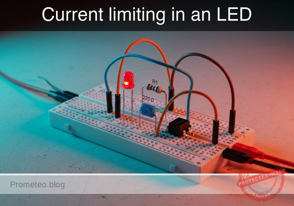
In this case, you will build a fundamental series circuit connecting a DC voltage source, a current-limiting resistor, and a Light Emitting Diode (LED).
Why it is useful:
* Component Protection: Prevents the LED from drawing excessive current and burning out instantly.
* Ohm’s Law Application: Visually demonstrates the relationship between Voltage, Current, and Resistance ($I = V/R$).
* Status Indication: Forms the basis for power indicators on almost every electronic device.
* Diagnostic Tooling: Simple LED circuits are often used to debug logic levels in complex systems.
Expected outcome:
* The LED lights up steadily without overheating.
* The current flowing through the circuit remains within the safe range (typically 10–20 mA).
* The voltage drop across the resistor corresponds to the supply voltage minus the LED forward voltage.
Target audience and level: Beginners and students starting with basic component analysis.
Materials
- V1: 5 V DC supply
- R1: 220 Ω resistor, function: current limiting
- D1: Red LED, function: light emission
- M1: Multimeter, function: current measurement (A)
- M2: Multimeter, function: voltage measurement (V)
Wiring guide
This circuit uses a series topology. We define the nodes as VCC (5V Source), 0 (Ground), and NODE_A (Intermediate connection).
- V1 (DC Source): Positive terminal connects to node
VCC. Negative terminal connects to node0. - R1 (Resistor): Connects between node
VCCand nodeNODE_A. - D1 (LED): Anode connects to node
NODE_A. Cathode connects to node0.
Conceptual block diagram

Schematic
[ SOURCE ]                  [ CURRENT CONTROL ]              [ OUTPUT / LOAD ]

    [ V1: 5V DC ] --(VCC)--> [ R1: 220 Ohm ] --(Node A)--> [ D1: Red LED ] --(0)--> [ GND ]
Measurements and tests
To validate Ohm’s Law and component safety:
- Calculate Expected Current:
- Assume LED Forward Voltage ($V_f$) $\approx$ 2.0 V.
- Voltage across R1: $V_{R1} = V_{source} – V_f = 5V – 2V = 3V$.
- Expected Current: $I = V_{R1} / R1 = 3V / 220\Omega \approx 13.6 mA$.
- Voltage Measurement: Set multimeter M2 to DC Volts. Measure across R1 (leads on
VCCandNODE_A). The reading should be approximately 3 V. - Current Measurement: Break the circuit at node
VCCor0and insert multimeter M1 in series (Amperemeter mode). The reading should be close to 13–14 mA. - Visual Check: The LED should emit a steady, bright red light.
SPICE netlist and simulation
Reference SPICE Netlist (ngspice) — excerptFull SPICE netlist (ngspice)
* Practical case: Current limiting in an LED

* --- Power Supply ---
* V1: 5V DC Supply connected between VCC and 0 (GND)
V1 VCC 0 DC 5

* --- Components ---
* R1: 220 Ohm Resistor
* Function: Current limiting
* Connected between VCC and NODE_A
R1 VCC NODE_A 220

* D1: Red LED
* Function: Light emission
* Anode connected to NODE_A, Cathode connected to 0 (GND)
D1 NODE_A 0 DLED

* --- Models ---
* Model for D1 (Red LED)
* Parameters: IS (Saturation Current), N (Emission Coefficient), RS (Series Resistance)
* ... (truncated in public view) ...
Copy this content into a .cir file and run with ngspice.
* Practical case: Current limiting in an LED

* --- Power Supply ---
* V1: 5V DC Supply connected between VCC and 0 (GND)
V1 VCC 0 DC 5

* --- Components ---
* R1: 220 Ohm Resistor
* Function: Current limiting
* Connected between VCC and NODE_A
R1 VCC NODE_A 220

* D1: Red LED
* Function: Light emission
* Anode connected to NODE_A, Cathode connected to 0 (GND)
D1 NODE_A 0 DLED

* --- Models ---
* Model for D1 (Red LED)
* Parameters: IS (Saturation Current), N (Emission Coefficient), RS (Series Resistance)
* Tuned for approximately 1.8V - 2.0V forward voltage drop
.model DLED D (IS=1e-14 N=2.5 RS=5 BV=5 IBV=10u)

* --- Analysis Directives ---
* Calculate DC operating point
.op

* Transient analysis (Required for .print output generation)
* Step: 100us, Stop: 10ms
.tran 100u 10m

* --- Output / Measurements ---
* Simulating M2 (Multimeter - Voltage): Probing NODE_A (Voltage across LED)
* Simulating M1 (Multimeter - Current): Probing I(V1) (Total circuit current)
* Note: I(V1) will be negative as current flows out of the voltage source.
.print tran V(VCC) V(NODE_A) I(V1)

.end
Simulation Results (Transient Analysis)

Show raw data table (108 rows)
Index   time            v(vcc)          v(node_a)       v1#branch
0	0.000000e+00	5.000000e+00	1.880179e+00	-1.41810e-02
1	1.000000e-06	5.000000e+00	1.880178e+00	-1.41810e-02
2	2.000000e-06	5.000000e+00	1.880178e+00	-1.41810e-02
3	4.000000e-06	5.000000e+00	1.880178e+00	-1.41810e-02
4	8.000000e-06	5.000000e+00	1.880178e+00	-1.41810e-02
5	1.600000e-05	5.000000e+00	1.880178e+00	-1.41810e-02
6	3.200000e-05	5.000000e+00	1.880178e+00	-1.41810e-02
7	6.400000e-05	5.000000e+00	1.880178e+00	-1.41810e-02
8	1.280000e-04	5.000000e+00	1.880178e+00	-1.41810e-02
9	2.280000e-04	5.000000e+00	1.880178e+00	-1.41810e-02
10	3.280000e-04	5.000000e+00	1.880178e+00	-1.41810e-02
11	4.280000e-04	5.000000e+00	1.880178e+00	-1.41810e-02
12	5.280000e-04	5.000000e+00	1.880178e+00	-1.41810e-02
13	6.280000e-04	5.000000e+00	1.880178e+00	-1.41810e-02
14	7.280000e-04	5.000000e+00	1.880178e+00	-1.41810e-02
15	8.280000e-04	5.000000e+00	1.880178e+00	-1.41810e-02
16	9.280000e-04	5.000000e+00	1.880178e+00	-1.41810e-02
17	1.028000e-03	5.000000e+00	1.880178e+00	-1.41810e-02
18	1.128000e-03	5.000000e+00	1.880178e+00	-1.41810e-02
19	1.228000e-03	5.000000e+00	1.880178e+00	-1.41810e-02
20	1.328000e-03	5.000000e+00	1.880178e+00	-1.41810e-02
21	1.428000e-03	5.000000e+00	1.880178e+00	-1.41810e-02
22	1.528000e-03	5.000000e+00	1.880178e+00	-1.41810e-02
23	1.628000e-03	5.000000e+00	1.880178e+00	-1.41810e-02
... (84 more rows) ...
Common mistakes and how to avoid them
- Reversed LED Polarity: Connecting the LED cathode to positive. Solution: Ensure the longer leg (Anode) faces the positive voltage side (towards R1).
- Omitting the Resistor: Connecting the LED directly to 5V. Solution: Always verify the resistor is in series before applying power to prevent destroying the LED.
- Measuring Current in Parallel: Attempting to measure current by probing across the LED like a voltmeter. Solution: Always break the circuit path and place the meter in series for current measurements.
Troubleshooting
- Symptom: LED does not light up.
- Cause: LED connected backwards or broken circuit.
- Fix: Check orientation (Anode/Cathode) and ensure all breadboard connections are tight.
- Symptom: LED flashes once and dies.
- Cause: No current limiting resistor used (LED burned out).
- Fix: Replace the LED and ensure R1 (220 Ω) is correctly installed.
- Symptom: LED is very dim.
- Cause: Resistance value is too high (e.g., using 10 kΩ instead of 220 Ω).
- Fix: Verify the resistor color bands or measure R1 with a multimeter.
- Symptom: Multimeter reads 0 A.
- Cause: Blown fuse in the multimeter or improper mode selection.
- Fix: Check probe connections (Com/mA) and ensure the meter dial is set to DC Current.
Possible improvements and extensions
- Variable Brightness: Replace R1 with a 1 kΩ potentiometer in series with a 100 Ω safety resistor to manually adjust the brightness.
- Multiple Colors: Swap the Red LED for Blue or Green and measure the change in current (different colors have different forward voltages, affecting the calculation).
More Practical Cases on Prometeo.blog
Find this product and/or books on this topic on Amazon
As an Amazon Associate, I earn from qualifying purchases. If you buy through this link, you help keep this project running.
Quick Quiz

Telecommunications Electronics Engineer and Computer Engineer (official degrees in Spain).

