
Level: Basic. Learn how to isolate a low-power control signal from a high-power motor circuit using an electromagnetic relay.
Objective and use case
In this practical case, you will build a circuit that utilizes a small pushbutton and a relay to control a high-current DC motor. The relay acts as an electromagnetic switch, allowing the low-power control side to activate the high-power load side without direct electrical connection between the distinct power rails (if separate grounds are used) or simply to handle currents exceeding the switch’s rating.
Why it is useful:
* Automotive systems: Used in starter motors where a small ignition key switch triggers a massive solenoid (relay) to crank the engine.
* Industrial automation: Allows low-voltage PLCs (24 V) to switch high-voltage AC or DC motors (110 V/220 V) safely.
* Safety isolation: Keeps high voltages away from the user interface (buttons and switches).
* Component protection: Prevents burning out delicate switches by offloading the high current switching to the relay contacts.
Expected outcome:
* When the pushbutton is pressed, the relay makes an audible «click.»
* The DC motor starts spinning immediately upon the click.
* Voltage across the relay coil measures 5 V (or rated control voltage).
* The flyback diode protects the switch from high-voltage spikes when the button is released.
Target audience and level: Students and hobbyists understanding basic electromechanical switching (Basic).
Materials
- V1: 5 V DC voltage source, function: Control circuit power supply.
- V2: 12 V DC voltage source, function: Motor (Power) circuit supply.
- S1: Momentary Pushbutton (Normally Open), function: Control switch.
- K1: SPDT Relay (5 V Coil), function: Electromechanical isolation and switching.
- D1: 1N4007 Diode, function: Flyback/Freewheeling diode for coil protection.
- M1: 12 V DC Motor, function: High-power load.
Wiring guide
This guide uses SPICE-friendly node names to define the connections. The nodes are: V_CTRL (5 V), V_PWR (12 V), COIL_IN, MOTOR_IN, and 0 (Ground).
- V1 (Positive): Connects to node
V_CTRL. - V1 (Negative): Connects to node
0. - V2 (Positive): Connects to node
V_PWR. - V2 (Negative): Connects to node
0. - S1: Connects between node
V_CTRLand nodeCOIL_IN. - K1 (Coil terminal A): Connects to node
COIL_IN. - K1 (Coil terminal B): Connects to node
0. - D1 (Cathode/Striped side): Connects to node
COIL_IN. - D1 (Anode): Connects to node
0. - K1 (Common/COM Contact): Connects to node
V_PWR. - K1 (Normally Open/NO Contact): Connects to node
MOTOR_IN. - M1 (Positive): Connects to node
MOTOR_IN. - M1 (Negative): Connects to node
0.
Note: In a physical application requiring galvanic isolation, the ground 0 for the control side (V1) and the power side (V2) would be kept separate. For this basic simulation model, they share a common reference.
Conceptual block diagram
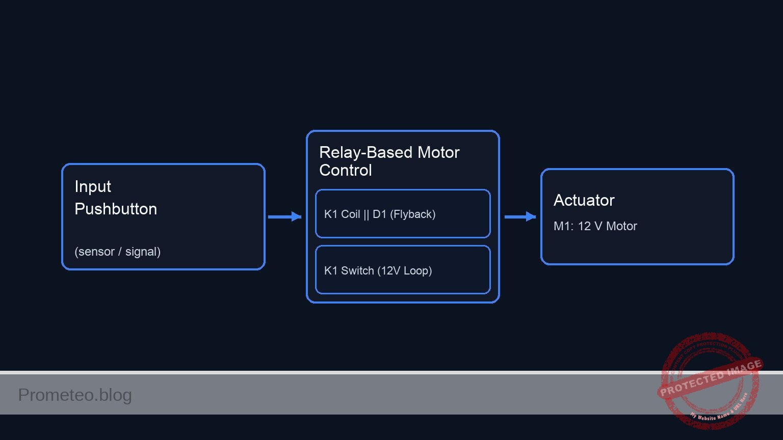
Schematic
+---------------------------------------------------------------------------------------------------------+
|                          DC MOTOR CONTROL WITH RELAY (UNIFIED DIAGRAM)                                  |
+---------------------------------------------------------------------------------------------------------+

      (High Power Loop: 12 V)
      [ V2: 12 V Source ] --(Node: V_PWR)--> [ K1: Relay Switch (COM->NO) ] --(Node: MOTOR_IN)--> [ M1: 12 V Motor ] --> [ GND ]
                                                        ^
                                                        |
                                                 (Magnetic Link)
                                                        |
      (Control Loop: 5 V)                                |
      [ V1: 5 V Source ] --(Node: V_CTRL)--> [ S1: Pushbutton ] --(Node: COIL_IN)--> [ Parallel: K1 Coil || D1 (Rev) ] --> [ GND ]

+---------------------------------------------------------------------------------------------------------+
|  LEGEND & NOTES:                                                                                        |
|  -->  : Signal/Power Flow                                                                               |
|  ||   : Components in Parallel (Coil and Diode share Node COIL_IN and GND)                              |
|  Rev  : Diode D1 is Reverse Biased (Cathode to COIL_IN, Anode to GND) to suppress flyback voltage.      |
|  Link : The current in the Control Loop generates the magnetic field to close the Switch in the Power Loop. |
+---------------------------------------------------------------------------------------------------------+
Measurements and tests
Follow these steps to validate your circuit assembly:
-
Coil Voltage Check:
- Set your multimeter to DC Voltage (20 V range).
- Connect probes across the relay coil terminals (
COIL_INand0). - Press S1. The reading should jump from 0 V to approx. 5 V.
-
Audible Confirmation:
- Press and release S1. Listen for the mechanical «click» of the relay armature moving. If you do not hear it, the coil is not energizing.
-
Load Voltage Verification:
- Connect the multimeter across the motor terminals.
- Press S1. The multimeter should read approx. 12 V (voltage of V2) and the motor should spin.
- Release S1. The voltage should drop to 0 V and the motor should coast to a stop.
-
Flyback Diode Test (Advanced):
- Without D1, monitoring
COIL_INwith an oscilloscope would reveal a large negative voltage spike when S1 is released. With D1 installed, this spike is clamped to approx. -0.7 V, protecting S1.
- Without D1, monitoring
SPICE netlist and simulation
Reference SPICE Netlist (ngspice) — excerptFull SPICE netlist (ngspice)
* Practical case: DC motor control with relay and pushbutton

* --- Models ---
* Generic Pushbutton Switch Model (Voltage Controlled)
.model SW_PB SW(Vt=2.5 Vh=0.1 Ron=0.01 Roff=10Meg)
* Relay Contact Switch Model (Controlled by Coil Voltage)
.model SW_RELAY SW(Vt=3.5 Vh=0.2 Ron=0.05 Roff=10Meg)
* 1N4007 Diode Model
.model D1N4007 D(IS=7.07e-9 RS=0.034 N=1.7 BV=1000 IBV=5e-6 CJO=1e-11 TT=1e-7)

* --- Power Supplies ---
* V1: Control Circuit Power (5V)
V1 V_CTRL 0 DC 5
* V2: Motor Circuit Power (12V)
V2 V_PWR 0 DC 12

* --- Control Circuit (Input) ---
* S1: Pushbutton.
* Modeled as a voltage-controlled switch driven by a PULSE source (V_ACT)
* to simulate the physical act of pressing the button.
* ... (truncated in public view) ...
Copy this content into a .cir file and run with ngspice.
* Practical case: DC motor control with relay and pushbutton

* --- Models ---
* Generic Pushbutton Switch Model (Voltage Controlled)
.model SW_PB SW(Vt=2.5 Vh=0.1 Ron=0.01 Roff=10Meg)
* Relay Contact Switch Model (Controlled by Coil Voltage)
.model SW_RELAY SW(Vt=3.5 Vh=0.2 Ron=0.05 Roff=10Meg)
* 1N4007 Diode Model
.model D1N4007 D(IS=7.07e-9 RS=0.034 N=1.7 BV=1000 IBV=5e-6 CJO=1e-11 TT=1e-7)

* --- Power Supplies ---
* V1: Control Circuit Power (5V)
V1 V_CTRL 0 DC 5
* V2: Motor Circuit Power (12V)
V2 V_PWR 0 DC 12

* --- Control Circuit (Input) ---
* S1: Pushbutton.
* Modeled as a voltage-controlled switch driven by a PULSE source (V_ACT)
* to simulate the physical act of pressing the button.
* Wiring: Connects V_CTRL to COIL_IN.
V_ACT ACT_NODE 0 PULSE(0 5 10m 1u 1u 245m 1s)
S1 V_CTRL COIL_IN ACT_NODE 0 SW_PB

* K1: Relay Coil
* Wiring: Coil Terminal A to COIL_IN, Coil Terminal B to 0.
* Modeled as Inductor + Resistor in series.
R_K1_COIL COIL_IN K1_INT 60
L_K1_COIL K1_INT 0 100m

* D1: Flyback Diode
* Wiring: Cathode to COIL_IN, Anode to 0.
* SPICE Syntax: D
D1 0 COIL_IN D1N4007

* --- Power Circuit (Output) ---
* K1: Relay Contact (Switch)
* Wiring: Common (COM) to V_PWR, Normally Open (NO) to MOTOR_IN.
* Controlled by the voltage at node COIL_IN.
S_K1_SW V_PWR MOTOR_IN COIL_IN 0 SW_RELAY

* M1: DC Motor
* Wiring: Positive to MOTOR_IN, Negative to 0.
* Modeled as an RL load (Resistance + Inductance).
R_M1 MOTOR_IN M1_INT 20
L_M1 M1_INT 0 10m

* --- Analysis Directives ---
.op
.tran 0.1m 250m

* --- Output Printing ---
* Must define INPUT (COIL_IN) and OUTPUT (MOTOR_IN)
.print tran V(COIL_IN) V(MOTOR_IN) V(ACT_NODE) I(L_M1)

.end
Simulation Results (Transient Analysis)

Show raw data table (2535 rows)
Index   time            v(coil_in)      v(motor_in)     v(act_node)     l_m1#branch
0	0.000000e+00	2.999953e-05	2.399995e-05	0.000000e+00	1.199998e-06
1	1.000000e-06	2.999953e-05	2.399995e-05	0.000000e+00	1.199998e-06
2	2.000000e-06	2.999953e-05	2.399995e-05	0.000000e+00	1.199998e-06
3	4.000000e-06	2.999953e-05	2.399995e-05	0.000000e+00	1.199998e-06
4	8.000000e-06	2.999953e-05	2.399995e-05	0.000000e+00	1.199998e-06
5	1.600000e-05	2.999953e-05	2.399995e-05	0.000000e+00	1.199998e-06
6	3.200000e-05	2.999953e-05	2.399995e-05	0.000000e+00	1.199998e-06
7	6.400000e-05	2.999953e-05	2.399995e-05	0.000000e+00	1.199998e-06
8	1.280000e-04	2.999953e-05	2.399995e-05	0.000000e+00	1.199998e-06
9	2.280000e-04	2.999953e-05	2.399995e-05	0.000000e+00	1.199998e-06
10	3.280000e-04	2.999953e-05	2.399995e-05	0.000000e+00	1.199998e-06
11	4.280000e-04	2.999953e-05	2.399995e-05	0.000000e+00	1.199998e-06
12	5.280000e-04	2.999953e-05	2.399995e-05	0.000000e+00	1.199998e-06
13	6.280000e-04	2.999953e-05	2.399995e-05	0.000000e+00	1.199998e-06
14	7.280000e-04	2.999953e-05	2.399995e-05	0.000000e+00	1.199998e-06
15	8.280000e-04	2.999953e-05	2.399995e-05	0.000000e+00	1.199998e-06
16	9.280000e-04	2.999953e-05	2.399995e-05	0.000000e+00	1.199998e-06
17	1.028000e-03	2.999953e-05	2.399995e-05	0.000000e+00	1.199998e-06
18	1.128000e-03	2.999953e-05	2.399995e-05	0.000000e+00	1.199998e-06
19	1.228000e-03	2.999953e-05	2.399995e-05	0.000000e+00	1.199998e-06
20	1.328000e-03	2.999953e-05	2.399995e-05	0.000000e+00	1.199998e-06
21	1.428000e-03	2.999953e-05	2.399995e-05	0.000000e+00	1.199998e-06
22	1.528000e-03	2.999953e-05	2.399995e-05	0.000000e+00	1.199998e-06
23	1.628000e-03	2.999953e-05	2.399995e-05	0.000000e+00	1.199998e-06
... (2511 more rows) ...
Common mistakes and how to avoid them
-
Omitting the Flyback Diode (D1):
- Error: Leaving out the diode across the relay coil.
- Consequence: The collapsing magnetic field generates a high-voltage spike (back EMF) that can arc across the switch contacts or destroy transistor drivers in future circuits.
- Solution: Always install a diode in reverse bias (Cathode to positive) across inductive loads.
-
Using the Wrong Relay Contacts (NC vs NO):
- Error: Connecting the motor to the Normally Closed (NC) pin instead of Normally Open (NO).
- Consequence: The motor runs continuously when the button is not pressed and stops when it is pressed.
- Solution: Identify the NO pin using the datasheet or a continuity test before soldering.
-
Mixing Power Rails:
- Error: Connecting the 12 V motor supply directly to the 5 V coil.
- Consequence: The relay coil will overheat and likely burn out due to over-voltage.
- Solution: Ensure the coil voltage matches the control supply (V1) and the contact rating matches the motor supply (V2).
Troubleshooting
-
Symptom: Relay clicks, but motor does not run.
- Cause: Burnt relay contacts or loose wire between COM/NO and the motor.
- Fix: Check continuity across COM and NO while the relay is held active.
-
Symptom: Relay does not click when S1 is pressed.
- Cause: Coil wiring error or S1 is faulty.
- Fix: Measure voltage at the coil terminals while pressing S1. If 0 V, check S1.
-
Symptom: Circuit resets or sparks occur at S1.
- Cause: Lack of flyback diode causing arcing.
- Fix: Install D1 immediately across the coil terminals.
Possible improvements and extensions
- Transistor Driver: Replace the direct pushbutton connection with an NPN transistor (e.g., 2N2222) to control the relay using a weak signal from an Arduino or microcontroller.
- Self-Latching Circuit: Add a second relay contact or wire the relay in a «latching» configuration with a separate «Stop» button (NC), so you don’t have to hold S1 to keep the motor running.
More Practical Cases on Prometeo.blog
Find this product and/or books on this topic on Amazon
As an Amazon Associate, I earn from qualifying purchases. If you buy through this link, you help keep this project running.
Quick Quiz

Telecommunications Electronics Engineer and Computer Engineer (official degrees in Spain).

