
Level: Basic – Understand how to use two SPDT relays to change polarity and direction of a DC motor.
Objective and use case
In this case, you will build a relay-based H-bridge circuit to control a DC motor. By using two Single Pole Double Throw (SPDT) relays, you will be able to drive the motor clockwise, counter-clockwise, or brake it using simple pushbuttons.
- Real-world scenarios:
- Automotive Power Windows: Reversing the motor to raise or lower the glass.
- Robotics: Controlling wheel direction for forward and backward movement.
- Industrial Conveyors: Changing the direction of a belt to route products.
-
Motorized Curtains: Opening and closing mechanisms.
-
Expected outcome:
- Idle State: When no buttons are pressed, the motor terminals are grounded (0 V difference), resulting in a dynamic brake (motor stops).
- Forward State: Pressing Button A applies +5 V to the motor; it spins Clockwise (CW).
- Reverse State: Pressing Button B applies -5 V (polarity swap) to the motor; it spins Counter-Clockwise (CCW).
- Braking/Safety: If both buttons are pressed simultaneously, both motor terminals connect to VCC, resulting in 0 V difference and the motor remains stopped.
Target audience: Hobbyists and students getting started with electromechanical control.
Materials
- V1: 5 V DC Power Supply, function: Main energy source.
- M1: 5 V DC Motor, function: The actuator to be controlled.
- K1: 5 V SPDT Relay, function: Controls the «Positive» side of the motor.
- K2: 5 V SPDT Relay, function: Controls the «Negative» side of the motor.
- S1: Momentary Pushbutton (NO), function: Activates Relay K1 (Forward).
- S2: Momentary Pushbutton (NO), function: Activates Relay K2 (Reverse).
- D1: 1N4007 Diode, function: Flyback protection for K1 coil.
- D2: 1N4007 Diode, function: Flyback protection for K2 coil.
Wiring guide
This guide uses node names to describe connections.
Nodes: VCC (5 V Supply), 0 (Ground), COIL_A, COIL_B, MOT_A, MOT_B.
- Power Supply:
- V1 (+): Connects to node
VCC. -
V1 (-): Connects to node
0. -
Control Circuit (Coils):
- S1: Connects between
VCCandCOIL_A. - K1 (Coil): Connects between
COIL_Aand0. - D1: Cathode to
COIL_A, Anode to0(Protects against inductive spikes). - S2: Connects between
VCCandCOIL_B. - K2 (Coil): Connects between
COIL_Band0. -
D2: Cathode to
COIL_B, Anode to0. -
Power Circuit (Motor Drive):
- K1 (Normally Open – NO): Connects to
VCC. - K1 (Normally Closed – NC): Connects to
0. - K1 (Common – COM): Connects to node
MOT_A. - K2 (Normally Open – NO): Connects to
VCC. - K2 (Normally Closed – NC): Connects to
0. - K2 (Common – COM): Connects to node
MOT_B. - M1: Connects between
MOT_AandMOT_B.
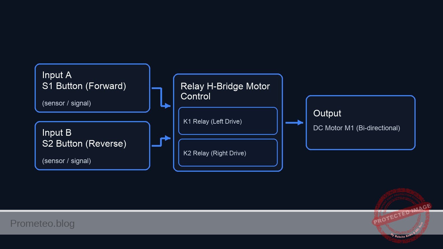
Conceptual block diagram
Schematic
+-------------------------------------------------------------------------+
|                DC MOTOR REVERSING CIRCUIT (H-BRIDGE)                    |
+-------------------------------------------------------------------------+

[ CONTROL SUBSYSTEM ]                                [ POWER SUBSYSTEM ]

      (Forward Input)                                   (Left Side Drive)
VCC --> [ S1 Button ]                                  VCC (NO)
            |                                             |
            v                                             v
    [ Node: COIL_A ]                               [ K1 Switch (COM) ] --(MOT_A)--+
            |                                      [  (Relay 1)      ]            |
            +--> [ K1 Coil || D1 ] --> GND                ^                       |
            |    (D1 is Reverse Biased)                   |                       |
            |                                             |                       |
            +----------(Magnetic Link)--------------------+                       |
                                                          |                       |
                                                  GND (NC) +                      |
                                                                                  v
                                                                           [ DC MOTOR ]
                                                                           [    M1    ]
                                                                                  ^
                                                  GND (NC) +                      |
                                                          |                       |
            +----------(Magnetic Link)--------------------+                       |
            |                                             |                       |
            |    (D2 is Reverse Biased)                   |                       |
            +--> [ K2 Coil || D2 ] --> GND         [ K2 Switch (COM) ] --(MOT_B)--+
            |                                      [  (Relay 2)      ]
    [ Node: COIL_B ]                                      ^
            ^                                             |
            |                                             |
VCC --> [ S2 Button ]                                  VCC (NO)
      (Reverse Input)                                   (Right Side Drive)

+-------------------------------------------------------------------------+
| LOGIC KEY:                                                              |
| 1. Idle: Both Switches connect COM to NC (GND). Motor is braked (0 V).   |
| 2. Press S1: K1 switches to NO (VCC). Current: VCC->MOT_A->MOT_B->GND.  |
| 3. Press S2: K2 switches to NO (VCC). Current: VCC->MOT_B->MOT_A->GND.  |
+-------------------------------------------------------------------------+
Measurements and tests
To validate the circuit, perform the following steps using a multimeter and visual inspection:
- Idle Check: Ensure neither S1 nor S2 is pressed. Measure voltage between
MOT_AandMOT_B.- Result: Should be 0 V. Both terminals are connected to GND via the NC contacts. The motor is locked (hard to turn by hand due to back EMF shorting).
- Forward Actuation: Press and hold S1.
- Result: K1 clicks. Measure voltage from
MOT_A(Red probe) toMOT_B(Black probe). Voltage should be approximately +5 V. Motor spins Clockwise.
- Result: K1 clicks. Measure voltage from
- Reverse Actuation: Release S1, then press and hold S2.
- Result: K2 clicks. Measure voltage from
MOT_AtoMOT_B. Voltage should be approximately -5 V. Motor spins Counter-Clockwise.
- Result: K2 clicks. Measure voltage from
- Double Press (Safety Test): Press both S1 and S2 simultaneously.
- Result: Both relays click. Voltage between
MOT_AandMOT_Bis 0 V (Both at 5 V potential). Motor does not move.
- Result: Both relays click. Voltage between
SPICE netlist and simulation
Reference SPICE Netlist (ngspice) — excerptFull SPICE netlist (ngspice)
* Practical case: DC Motor Reversing
.width out=256
* Ngspice Netlist
*
* Description: H-Bridge configuration using two SPDT relays to control a DC motor.
* Logic:
* - S1 Pressed -> K1 Active -> MOT_A = 5V, MOT_B = 0V (Forward)
* - S2 Pressed -> K2 Active -> MOT_A = 0V, MOT_B = 5V (Reverse)
* - None Pressed -> MOT_A = 0V, MOT_B = 0V (Stop/Brake)
*
* Simulation Time: 10ms (Captures S1 pulse at 1ms and S2 pulse at 5ms)
.tran 10u 10m

* -----------------------------------------------------------------------------
* Power Supply
* -----------------------------------------------------------------------------
* V1: 5V DC Power Supply, function: Main energy source.
* Connected between VCC (+) and 0 (-).
V1 VCC 0 DC 5

* ... (truncated in public view) ...
Copy this content into a .cir file and run with ngspice.
* Practical case: DC Motor Reversing
.width out=256
* Ngspice Netlist
*
* Description: H-Bridge configuration using two SPDT relays to control a DC motor.
* Logic:
* - S1 Pressed -> K1 Active -> MOT_A = 5V, MOT_B = 0V (Forward)
* - S2 Pressed -> K2 Active -> MOT_A = 0V, MOT_B = 5V (Reverse)
* - None Pressed -> MOT_A = 0V, MOT_B = 0V (Stop/Brake)
*
* Simulation Time: 10ms (Captures S1 pulse at 1ms and S2 pulse at 5ms)
.tran 10u 10m

* -----------------------------------------------------------------------------
* Power Supply
* -----------------------------------------------------------------------------
* V1: 5V DC Power Supply, function: Main energy source.
* Connected between VCC (+) and 0 (-).
V1 VCC 0 DC 5

* -----------------------------------------------------------------------------
* User Inputs (Pushbuttons)
* -----------------------------------------------------------------------------
* Modeled as Voltage Controlled Switches (S1, S2) driven by Pulse Sources.
* This strictly simulates the user pressing the button at specific times.

* Stimulus for S1 (Forward Request)
* Pulse: 0V to 5V, starts at 1ms, duration 2ms.
V_USER_S1 CTRL_S1 0 PULSE(0 5 1m 1u 1u 2m 10m)

* Stimulus for S2 (Reverse Request)
* Pulse: 0V to 5V, starts at 5ms, duration 2ms.
V_USER_S2 CTRL_S2 0 PULSE(0 5 5m 1u 1u 2m 10m)

* S1: Momentary Pushbutton (NO)
* Connects VCC to COIL_A when activated by V_USER_S1.
S1 VCC COIL_A CTRL_S1 0 SW_PUSH

* S2: Momentary Pushbutton (NO)
* Connects VCC to COIL_B when activated by V_USER_S2.
S2 VCC COIL_B CTRL_S2 0 SW_PUSH

* -----------------------------------------------------------------------------
* Control Circuit (Relay Coils)
* -----------------------------------------------------------------------------
* Relay K1 Coil Circuit
* K1 Coil: Connects between COIL_A and 0. Modeled as L+R.
L_K1 COIL_A K1_INT 10m
R_K1 K1_INT 0 100
* D1: 1N4007 Diode, function: Flyback protection.
* Cathode to COIL_A, Anode to 0.
D1 0 COIL_A D_1N4007

* Relay K2 Coil Circuit
* K2 Coil: Connects between COIL_B and 0. Modeled as L+R.
L_K2 COIL_B K2_INT 10m
R_K2 K2_INT 0 100
* D2: 1N4007 Diode, function: Flyback protection.
* Cathode to COIL_B, Anode to 0.
D2 0 COIL_B D_1N4007

* -----------------------------------------------------------------------------
* Power Circuit (Motor Drive via Relay Contacts)
* -----------------------------------------------------------------------------
* Relay K1 Contacts (SPDT)
* COM: MOT_A
* NO: VCC (Connected when Coil is Energized/High)
* NC: 0   (Connected when Coil is De-energized/Low)
S_K1_NO VCC MOT_A COIL_A 0 SW_NO_RELAY
S_K1_NC MOT_A 0   COIL_A 0 SW_NC_RELAY

* Relay K2 Contacts (SPDT)
* COM: MOT_B
* NO: VCC (Connected when Coil is Energized/High)
* NC: 0   (Connected when Coil is De-energized/Low)
S_K2_NO VCC MOT_B COIL_B 0 SW_NO_RELAY
S_K2_NC MOT_B 0   COIL_B 0 SW_NC_RELAY

* M1: 5 V DC Motor
* Modeled as a resistive load (50 Ohms) to visualize voltage polarity.
* Connects between MOT_A and MOT_B.
R_M1 MOT_A MOT_B 50

* -----------------------------------------------------------------------------
* Component Models
* -----------------------------------------------------------------------------
* Standard Diode Model
.model D_1N4007 D(IS=1N N=1 RS=0.1 BV=1000 IBV=10u)

* Pushbutton Switch Model (Normally Open)
* Closes (Low R) when Control Voltage > 2.5V
.model SW_PUSH SW(Vt=2.5 Vh=0.1 Ron=0.01 Roff=10Meg)

* Relay Contact Models
* NO (Normally Open): Conducts when Coil > 2.5V
.model SW_NO_RELAY SW(Vt=2.5 Vh=0.1 Ron=0.01 Roff=10Meg)

* NC (Normally Closed): Conducts when Coil < 2.5V
* SPICE SW Logic: If V < Vt, R = Roff. If V > Vt, R = Ron.
* For NC: We want Low R when V < Vt. So Roff=0.01, Ron=10Meg.
.model SW_NC_RELAY SW(Vt=2.5 Vh=0.1 Ron=10Meg Roff=0.01)

* -----------------------------------------------------------------------------
* Output Directives
* -----------------------------------------------------------------------------
* Outputs: Motor Terminals (MOT_A, MOT_B)
* Inputs: Coil Control Voltages (COIL_A, COIL_B)
.print tran V(MOT_A) V(MOT_B) V(COIL_A) V(COIL_B) I(L_K1)

.op
.end
Simulation Results (Transient Analysis)

Show raw data table (1104 rows)
Index   time            v(mot_a)        v(mot_b)        v(coil_a)       v(coil_b)       l_k1#branch
0	0.000000e+00	5.000000e-09	5.000000e-09	4.999931e-05	4.999931e-05	4.999931e-07
1	1.000000e-07	5.000000e-09	5.000000e-09	4.999931e-05	4.999931e-05	4.999931e-07
2	2.000000e-07	5.000000e-09	5.000000e-09	4.999931e-05	4.999931e-05	4.999931e-07
3	4.000000e-07	5.000000e-09	5.000000e-09	4.999931e-05	4.999931e-05	4.999931e-07
4	8.000000e-07	5.000000e-09	5.000000e-09	4.999931e-05	4.999931e-05	4.999931e-07
5	1.600000e-06	5.000000e-09	5.000000e-09	4.999931e-05	4.999931e-05	4.999931e-07
6	3.200000e-06	5.000000e-09	5.000000e-09	4.999931e-05	4.999931e-05	4.999931e-07
7	6.400000e-06	5.000000e-09	5.000000e-09	4.999931e-05	4.999931e-05	4.999931e-07
8	1.280000e-05	5.000000e-09	5.000000e-09	4.999931e-05	4.999931e-05	4.999931e-07
9	2.280000e-05	5.000000e-09	5.000000e-09	4.999931e-05	4.999931e-05	4.999931e-07
10	3.280000e-05	5.000000e-09	5.000000e-09	4.999931e-05	4.999931e-05	4.999931e-07
11	4.280000e-05	5.000000e-09	5.000000e-09	4.999931e-05	4.999931e-05	4.999931e-07
12	5.280000e-05	5.000000e-09	5.000000e-09	4.999931e-05	4.999931e-05	4.999931e-07
13	6.280000e-05	5.000000e-09	5.000000e-09	4.999931e-05	4.999931e-05	4.999931e-07
14	7.280000e-05	5.000000e-09	5.000000e-09	4.999931e-05	4.999931e-05	4.999931e-07
15	8.280000e-05	5.000000e-09	5.000000e-09	4.999931e-05	4.999931e-05	4.999931e-07
16	9.280000e-05	5.000000e-09	5.000000e-09	4.999931e-05	4.999931e-05	4.999931e-07
17	1.028000e-04	5.000000e-09	5.000000e-09	4.999931e-05	4.999931e-05	4.999931e-07
18	1.128000e-04	5.000000e-09	5.000000e-09	4.999931e-05	4.999931e-05	4.999931e-07
19	1.228000e-04	5.000000e-09	5.000000e-09	4.999931e-05	4.999931e-05	4.999931e-07
20	1.328000e-04	5.000000e-09	5.000000e-09	4.999931e-05	4.999931e-05	4.999931e-07
21	1.428000e-04	5.000000e-09	5.000000e-09	4.999931e-05	4.999931e-05	4.999931e-07
22	1.528000e-04	5.000000e-09	5.000000e-09	4.999931e-05	4.999931e-05	4.999931e-07
23	1.628000e-04	5.000000e-09	5.000000e-09	4.999931e-05	4.999931e-05	4.999931e-07
... (1080 more rows) ...
Common mistakes and how to avoid them
- Wiring the Motor to NO/NC instead of COM:
- Mistake: Connecting the motor to the Normally Open or Closed pins, and power to the Common pin.
- Solution: Always connect the Load (Motor) to the Common (COM) pin of the SPDT relay for H-bridge configurations. Power and Ground go to NO and NC.
- Omitting Flyback Diodes:
- Mistake: Forgetting D1 and D2 across the relay coils.
- Solution: Always install diodes in reverse bias across coils to prevent high-voltage spikes from damaging switches or power supplies when the relay turns off.
- Using SPST Relays:
- Mistake: Attempting this topology with 4-pin relays that lack a Normally Closed contact.
- Solution: Ensure you use 5-pin SPDT relays so the motor can be grounded when the relay is off.
Troubleshooting
- Motor vibrates but does not spin:
- Cause: Power supply current is insufficient.
- Fix: Check the current rating of your power supply; motors draw high current upon startup.
- Relay clicks but motor does not move:
- Cause: Burnt internal contacts or loose wiring on the COM/NO/NC terminals.
- Fix: Verify continuity between COM and NO when the relay is active using a multimeter.
- Sparks visible inside the relay:
- Cause: Inductive load kickback from the motor.
- Fix: While not always fatal, adding a small capacitor (e.g., 100 nF) across the motor terminals can reduce arcing and noise.
Possible improvements and extensions
- Limit Switches: Add Normally Closed limit switches in series with the relay coils (
COIL_AandCOIL_B) to automatically stop the motor when a mechanism reaches its end of travel. - Speed Control: Insert a high-wattage rheostat or a PWM transistor driver in series with the main
VCCsupply to the relay contacts (not the coils) to vary the motor speed.
More Practical Cases on Prometeo.blog
Find this product and/or books on this topic on Amazon
As an Amazon Associate, I earn from qualifying purchases. If you buy through this link, you help keep this project running.
Quick Quiz

Telecommunications Electronics Engineer and Computer Engineer (official degrees in Spain).

