
Level: Basic. Implement a logic circuit where an alarm sounds only if two distinct sensors are activated simultaneously.
Objective and use case
In this tutorial, you will build a security logic circuit using a 74HC08 (AND gate) integrated circuit. The circuit processes signals from two independent switches (simulating a door and a window sensor) and activates an output LED only when both switches are closed at the same time.
Why it is useful:
* Safety Interlocks: Ensures machinery operates only when an operator presses two buttons simultaneously, keeping both hands away from danger.
* Security Systems: Triggers a specific high-priority alarm only when multiple zones are breached simultaneously.
* Data Validation: Logic gates are fundamental for validating that two necessary conditions (e.g., «System Ready» AND «Start Command») are met before executing an action.
Expected outcome:
* Input A (Low) + Input B (Low): LED remains OFF (0 V output).
* Input A (High) + Input B (Low): LED remains OFF (0 V output).
* Input A (Low) + Input B (High): LED remains OFF (0 V output).
* Input A (High) + Input B (High): LED turns ON (~5 V output).
* Target audience: Electronics students and hobbyists getting started with digital logic.
Materials
- V1: 5 V DC supply, function: Main power source.
- S1: SPST Switch, function: Sensor A (Door).
- S2: SPST Switch, function: Sensor B (Window).
- R1: 10 kΩ resistor, function: Pull-down for Sensor A (prevents floating state).
- R2: 10 kΩ resistor, function: Pull-down for Sensor B.
- U1: 74HC08 Quad 2-Input AND Gate, function: Logic decision core.
- R3: 330 Ω resistor, function: LED current limiting.
- D1: Red LED, function: Alarm visual indicator.
Pin-out of the IC used
Selected Chip: 74HC08 (Quad 2-Input AND Gate).
Note: This chip contains four independent gates. We will use only one.
| Pin | Name | Logic function | Connection in this case |
|---|---|---|---|
| 1 | 1A | Input A | Connect to Node SENSOR_A |
| 2 | 1B | Input B | Connect to Node SENSOR_B |
| 3 | 1Y | Output | Connect to Node ALARM_OUT |
| 7 | GND | Ground | Connect to Node 0 (GND) |
| 14 | VCC | Power Supply | Connect to Node VCC (+5 V) |
Wiring guide
Construct the circuit following these connections using specific node names:
- V1: Connect positive terminal to node
VCCand negative terminal to node0. - U1 Power: Connect Pin 14 to
VCCand Pin 7 to0. - S1: Connect one side to
VCCand the other side to nodeSENSOR_A. - R1: Connect between node
SENSOR_Aand node0. - S2: Connect one side to
VCCand the other side to nodeSENSOR_B. - R2: Connect between node
SENSOR_Band node0. - U1 Logic:
- Connect Pin 1 to node
SENSOR_A. - Connect Pin 2 to node
SENSOR_B. - Connect Pin 3 to node
ALARM_OUT.
- Connect Pin 1 to node
- Output Stage:
- R3: Connect between node
ALARM_OUTand nodeLED_ANODE. - D1: Connect Anode to node
LED_ANODEand Cathode to node0.
- R3: Connect between node
Conceptual block diagram
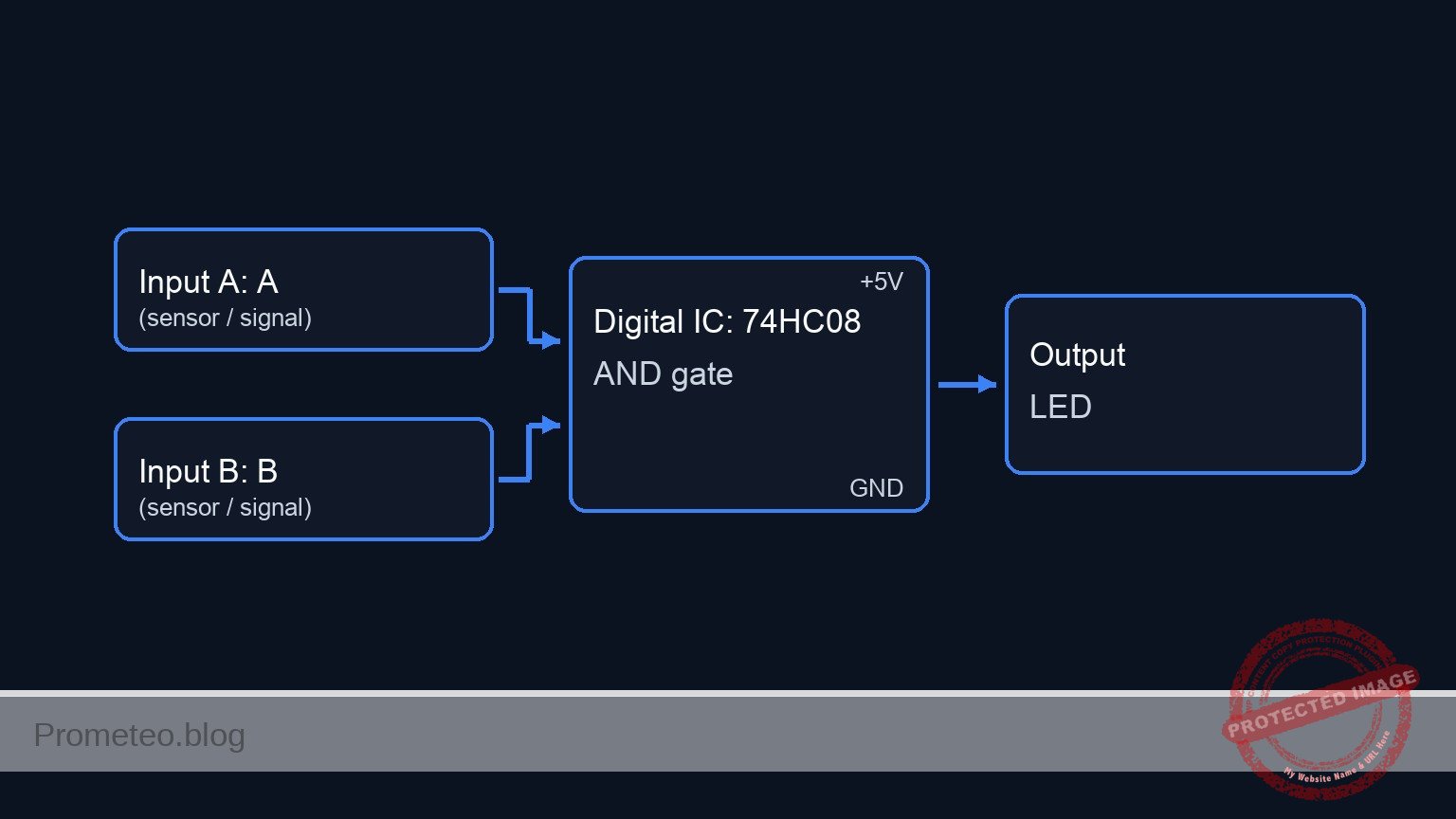
Schematic
[ INPUT SENSORS ]                          [ LOGIC CORE ]                       [ OUTPUT ALARM ]

                                                   +--------------+
    [ VCC ] --> [ S1: Door ] --(SENSOR_A)--------->| Pin 1        |
                                   |               |              |
                                   +-> [ R1: 10k ] |              |
                                          |        |  U1: 74HC08  |
                                       [ GND ]     |  (AND Gate)  |--(ALARM_OUT)--> [ R3: 330 Ω ] --> [ D1: LED ] --> [ GND ]
                                                   |              |
                                                   |              |
    [ VCC ] --> [ S2: Window ] --(SENSOR_B)------->| Pin 2        |
                                   |               |              |
                                   +-> [ R2: 10k ] | Power:       |
                                          |        | 14(VCC), 7(0)|
                                       [ GND ]     +--------------+
Truth table
The 74HC08 output is High (1) only if both inputs are High (1).
| Sensor A (S1) | Sensor B (S2) | Output (Pin 3) | LED State |
|---|---|---|---|
| 0 (Open) | 0 (Open) | 0 (Low) | OFF |
| 0 (Open) | 1 (Closed) | 0 (Low) | OFF |
| 1 (Closed) | 0 (Open) | 0 (Low) | OFF |
| 1 (Closed) | 1 (Closed) | 1 (High) | ON |
Measurements and tests
- Power Verification: Measure voltage between
VCCand0. It should be stable at 5 V. - Idle State: Ensure both S1 and S2 are open. Measure voltage at Pin 1 and Pin 2 of U1. Both should be 0 V (Logic 0). The LED should be OFF.
- Single Trigger Test: Close S1 only. Pin 1 should read 5 V, Pin 2 should read 0 V. Measure Pin 3 (Output); it should remain 0 V. Repeat for S2 only.
- Alarm Activation: Close both S1 and S2. Measure Pin 1 and Pin 2; both must be 5 V. Measure Pin 3; it should jump to ~5 V (Logic 1).
- Output Current: Check that D1 lights up brightly. The voltage drop across R3 should be approximately 3 V (depending on LED color).
SPICE netlist and simulation
Reference SPICE Netlist (ngspice) — excerptFull SPICE netlist (ngspice)
* Title: Practical case: Dual sensor alarm activation

* ==============================================================================
* Models
* ==============================================================================
* Generic Red LED Model
* IS: Saturation current, N: Emission coefficient, RS: Series resistance
.model DLED D(IS=1e-14 N=1.5 RS=5 BV=5 IBV=10u CJO=10p TT=10n)

* Voltage Controlled Switch Model (for S1, S2)
* Simulates a physical SPST switch
* Vt: Threshold voltage (2.5V), Ron: On resistance (1 ohm), Roff: Off resistance (100Meg)
.model SW_SENSOR SW(Vt=2.5 Ron=1 Roff=100Meg)

* ==============================================================================
* Subcircuits
* ==============================================================================
* U1: 74HC08 Quad 2-Input AND Gate (Single Gate Implementation)
* Pins: 1=A, 2=B, 3=Y, 7=GND, 14=VCC
.subckt 74HC08_GATE 1 2 3 7 14
* Behavioral implementation using continuous sigmoid functions for convergence robustness.
* Logic: V_out = VCC * sigmoid(A) * sigmoid(B)
* The slope factor (50) ensures a sharp transition near the 2.5V threshold.
B_LOGIC 3 7 V = V(14) * (1 / (1 + exp(-50 * (V(1) - 2.5)))) * (1 / (1 + exp(-50 * (V(2) - 2.5))))
.ends

* ==============================================================================
* Main Circuit
* ==============================================================================

* ... (truncated in public view) ...
Copy this content into a .cir file and run with ngspice.
* Title: Practical case: Dual sensor alarm activation

* ==============================================================================
* Models
* ==============================================================================
* Generic Red LED Model
* IS: Saturation current, N: Emission coefficient, RS: Series resistance
.model DLED D(IS=1e-14 N=1.5 RS=5 BV=5 IBV=10u CJO=10p TT=10n)

* Voltage Controlled Switch Model (for S1, S2)
* Simulates a physical SPST switch
* Vt: Threshold voltage (2.5V), Ron: On resistance (1 ohm), Roff: Off resistance (100Meg)
.model SW_SENSOR SW(Vt=2.5 Ron=1 Roff=100Meg)

* ==============================================================================
* Subcircuits
* ==============================================================================
* U1: 74HC08 Quad 2-Input AND Gate (Single Gate Implementation)
* Pins: 1=A, 2=B, 3=Y, 7=GND, 14=VCC
.subckt 74HC08_GATE 1 2 3 7 14
* Behavioral implementation using continuous sigmoid functions for convergence robustness.
* Logic: V_out = VCC * sigmoid(A) * sigmoid(B)
* The slope factor (50) ensures a sharp transition near the 2.5V threshold.
B_LOGIC 3 7 V = V(14) * (1 / (1 + exp(-50 * (V(1) - 2.5)))) * (1 / (1 + exp(-50 * (V(2) - 2.5))))
.ends

* ==============================================================================
* Main Circuit
* ==============================================================================

* --- Power Supply ---
* V1: 5 V DC supply (Main Power)
V1 VCC 0 DC 5

* --- Actuation Control Signals (Simulation Stimuli) ---
* These voltage sources act as the "hand" pressing the switches.
* They define the timing for the Truth Table test.
* ACT_A: Period 200us (High 0-100us)
V_ACT_A ACT_A 0 PULSE(0 5 0 1u 1u 100u 200u)
* ACT_B: Period 400us (High 0-200us)
V_ACT_B ACT_B 0 PULSE(0 5 0 1u 1u 200u 400u)

* --- Input A: Door Sensor ---
* S1: SPST Switch. Connects VCC to SENSOR_A when ACT_A is High (>2.5V).
S1 VCC SENSOR_A ACT_A 0 SW_SENSOR
* R1: 10 kΩ resistor. Pull-down for Sensor A.
R1 SENSOR_A 0 10k

* --- Input B: Window Sensor ---
* S2: SPST Switch. Connects VCC to SENSOR_B when ACT_B is High (>2.5V).
S2 VCC SENSOR_B ACT_B 0 SW_SENSOR
* R2: 10 kΩ resistor. Pull-down for Sensor B.
R2 SENSOR_B 0 10k

* --- Logic Core: U1 (74HC08) ---
* Instantiating the logic gate subcircuit.
* Mapping: Pin 1->SENSOR_A, Pin 2->SENSOR_B, Pin 3->ALARM_OUT, Pin 7->0, Pin 14->VCC
XU1 SENSOR_A SENSOR_B ALARM_OUT 0 VCC 74HC08_GATE

* --- Output Stage ---
* R3: 330 Ω resistor (Current limiting)
R3 ALARM_OUT LED_ANODE 330
* D1: Red LED (Visual indicator)
D1 LED_ANODE 0 DLED

* ==============================================================================
* Analysis Directives
* ==============================================================================
* Transient analysis: Step 1us, Stop 500us
* This duration covers all combinations of the input pulses (00, 01, 10, 11).
.tran 1u 500u

* Print required nodes for log output
.print tran V(SENSOR_A) V(SENSOR_B) V(ALARM_OUT) V(LED_ANODE)

* Calculate DC operating point
.op

.end
Simulation Results (Transient Analysis)

Show raw data table (1294 rows)
Index   time            v(sensor_a)     v(sensor_b)     v(alarm_out)
0	0.000000e+00	4.999500e-04	4.999500e-04	1.403014e-108
1	1.000000e-08	4.999500e-04	4.999500e-04	1.403014e-108
2	2.000000e-08	4.999500e-04	4.999500e-04	1.403014e-108
3	4.000000e-08	4.999500e-04	4.999500e-04	1.403014e-108
4	8.000000e-08	4.999500e-04	4.999500e-04	1.403014e-108
5	1.600000e-07	4.999500e-04	4.999500e-04	1.403014e-108
6	3.200000e-07	4.999500e-04	4.999500e-04	1.403014e-108
7	3.562500e-07	4.999500e-04	4.999500e-04	1.403014e-108
8	4.196875e-07	4.999500e-04	4.999500e-04	1.403014e-108
9	4.372461e-07	4.999500e-04	4.999500e-04	1.403014e-108
10	4.679736e-07	4.999500e-04	4.999500e-04	1.403014e-108
11	4.795524e-07	4.999500e-04	4.999500e-04	1.403014e-108
12	4.902290e-07	4.999500e-04	4.999500e-04	1.403014e-108
13	5.023412e-07	4.999500e+00	4.999500e+00	5.000000e+00
14	5.138119e-07	4.999500e+00	4.999500e+00	5.000000e+00
15	5.256739e-07	4.999500e+00	4.999500e+00	5.000000e+00
16	5.378128e-07	4.999500e+00	4.999500e+00	5.000000e+00
17	5.539238e-07	4.999500e+00	4.999500e+00	5.000000e+00
18	5.828205e-07	4.999500e+00	4.999500e+00	5.000000e+00
19	6.384927e-07	4.999500e+00	4.999500e+00	5.000000e+00
20	7.166884e-07	4.999500e+00	4.999500e+00	5.000000e+00
21	8.730798e-07	4.999500e+00	4.999500e+00	5.000000e+00
22	1.000000e-06	4.999500e+00	4.999500e+00	5.000000e+00
23	1.031278e-06	4.999500e+00	4.999500e+00	5.000000e+00
... (1270 more rows) ...
Common mistakes and how to avoid them
- Floating Inputs: Omitting R1 or R2 causes the inputs to «float» when switches are open. The 74HC08 may pick up noise and trigger erratically. Solution: Always use pull-down resistors (10 kΩ) connected to ground.
- Missing Power to IC: Students often wire the logic pins but forget Pins 14 (VCC) and 7 (GND). Solution: Always wire power rails first.
- No Current Limiting: Connecting the LED directly to the IC output without R3 will damage the LED or the 74HC08. Solution: Ensure a 220 Ω to 470 Ω resistor is in series with the LED.
Troubleshooting
- LED never turns ON:
- Check if the LED polarity is correct (Anode to resistor, Cathode to ground).
- Verify the 74HC08 has power on Pin 14.
- Ensure both switches are making good contact.
- LED acts erratically or turns ON when switches are OFF:
- Check for missing pull-down resistors R1 and R2.
- Verify that you are using a 74HC08 (AND) and not a 74HC32 (OR) or 74HC00 (NAND).
- LED is very dim:
- R3 value might be too high (e.g., 100 kΩ instead of 330 Ω).
- Source voltage V1 might be too low (< 3 V).
Possible improvements and extensions
- Audible Alarm: Connect a 5 V active buzzer in parallel with the LED (and its resistor) or use a transistor driver to sound a noise when the alarm triggers.
- Memory Latch: Feed the output into a Set-Reset (SR) Latch or Flip-Flop so that once the alarm is triggered, it stays ON even if the sensors are closed again, requiring a manual reset button.
More Practical Cases on Prometeo.blog
Find this product and/or books on this topic on Amazon
As an Amazon Associate, I earn from qualifying purchases. If you buy through this link, you help keep this project running.
Quick Quiz

Telecommunications Electronics Engineer and Computer Engineer (official degrees in Spain).

