
Level: Basic — Implement a logic circuit that triggers an alarm if either of two sensors detects an intrusion.
Objective and use case
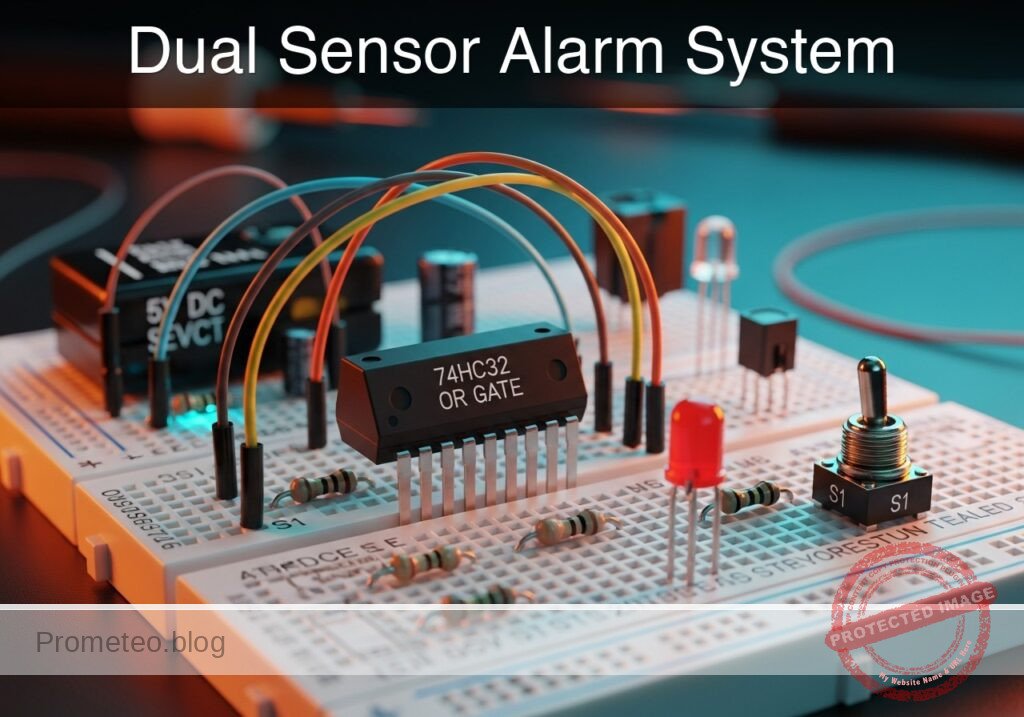
In this practical case, you will build a digital logic circuit using a 74HC32 (OR gate) integrated circuit. The circuit monitors two switches representing door sensors; if either switch is activated (logic HIGH), the output LED (alarm) turns on.
Why it is useful:
* Home Security: Simulates a system where opening either the front door or the back door triggers the siren.
* Automotive Safety: Functions like the dashboard «door open» light, which illuminates if any passenger door is not fully closed.
* Industrial Controls: Acts as a simplified fault monitor where multiple error signals can trigger a single warning light.
Expected outcome:
* Standby State: When both switches are open (0 V input), the LED remains OFF.
* Active State 1: When Switch A is closed (5 V input), the LED turns ON.
* Active State 2: When Switch B is closed (5 V input), the LED turns ON.
* Dual Active State: When both switches are closed, the LED remains ON.
* Target Audience: Electronics students and hobbyists learning basic digital logic gates.
Materials
- V1: 5 V DC power supply or battery pack
- U1: 74HC32 Quad 2-input OR gate IC
- S1: SPST toggle switch or push-button, function: Front Door Sensor (Input A)
- S2: SPST toggle switch or push-button, function: Back Door Sensor (Input B)
- R1: 10 kΩ resistor, function: pull-down for Input A
- R2: 10 kΩ resistor, function: pull-down for Input B
- R3: 330 Ω resistor, function: LED current limiting
- D1: Red LED, function: Alarm indicator
- Breadboard and hook-up wires
Pin-out of the IC used
Selected Chip: 74HC32 (Quad 2-input OR gate)
| Pin | Name | Logic function | Connection in this case |
|---|---|---|---|
| 1 | 1A | Input A (Gate 1) | Connected to S1 and R1 |
| 2 | 1B | Input B (Gate 1) | Connected to S2 and R2 |
| 3 | 1Y | Output (Gate 1) | Connected to R3 (LED driver) |
| 7 | GND | Ground | Connected to 0 (Negative rail) |
| 14 | VCC | Positive Supply | Connected to 5 V rail |
Wiring guide
Construct the circuit on the breadboard following these connections. The node names (e.g., IN_A, VCC) indicate electrical junctions.
- Power Supply:
- V1: Positive terminal to node
VCC. - V1: Negative terminal to node
0(GND).
- V1: Positive terminal to node
- IC Power:
- U1 (Pin 14): Connect to
VCC. - U1 (Pin 7): Connect to
0.
- U1 (Pin 14): Connect to
- Sensor A (Front Door):
- S1: Connect between
VCCand nodeIN_A. - R1: Connect between node
IN_Aand0(Functions as a pull-down resistor to ensure logic 0 when switch is open). - U1 (Pin 1): Connect to node
IN_A.
- S1: Connect between
- Sensor B (Back Door):
- S2: Connect between
VCCand nodeIN_B. - R2: Connect between node
IN_Band0(Functions as a pull-down resistor). - U1 (Pin 2): Connect to node
IN_B.
- S2: Connect between
- Output Stage:
- U1 (Pin 3): Connect to node
SIG_OUT. - R3: Connect between node
SIG_OUTand nodeLED_ANODE. - D1: Anode to node
LED_ANODE, Cathode to0.
- U1 (Pin 3): Connect to node
Conceptual block diagram
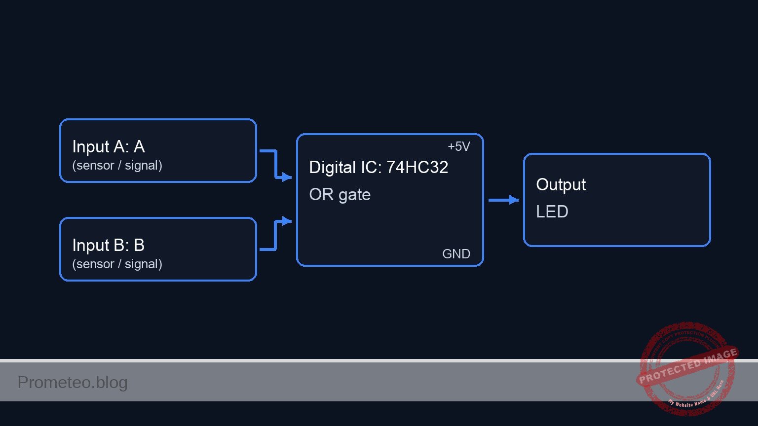
Schematic
[ INPUT SENSORS ]                        [ LOGIC PROCESSING ]                  [ OUTPUT ALARM ]

[ VCC ] --> [ S1: Front Door ] --+--(IN_A)--> [ Pin 1 ] --+
                                 |                        |
                           [ R1: 10k ]                    |
                                 |                        v
                               [ GND ]             +-------------+
                                                   |  U1: 74HC32 |
                                                   |  (OR Gate)  | --(Pin 3)--> [ R3: 330 ] --> [ D1: LED ] --> GND
                                                   +-------------+
                               [ GND ]                    ^
                                 |                        |
                           [ R2: 10k ]                    |
                                 |                        |
[ VCC ] --> [ S2: Back Door  ] --+--(IN_B)--> [ Pin 2 ] --+
Truth table
The 74HC32 behaves according to the standard OR logic:
| Sensor A (S1) | Sensor B (S2) | Pin 1 (Volts) | Pin 2 (Volts) | Output Pin 3 (Volts) | LED State |
|---|---|---|---|---|---|
| Open | Open | 0 V | 0 V | 0 V (LOW) | OFF |
| Open | Closed | 0 V | 5 V | 5 V (HIGH) | ON |
| Closed | Open | 5 V | 0 V | 5 V (HIGH) | ON |
| Closed | Closed | 5 V | 5 V | 5 V (HIGH) | ON |
Measurements and tests
- Supply Check: Before inserting the IC, power up the rails and measure the voltage between
VCCand0. It should read approximately 5 V. - Input Verification:
- Keep U1 inserted. Measure voltage at Pin 1 relative to GND. It should be 0 V.
- Press S1. The voltage at Pin 1 should jump to ~5 V.
- Repeat for S2 and Pin 2.
- Logic Logic Test:
- Ensure both switches are open. Measure Pin 3 (Output); it should be close to 0 V.
- Close S1 only. Measure Pin 3; it should be close to 5 V. The LED should light up.
- Close S2 only. Measure Pin 3; it should be close to 5 V. The LED should light up.
SPICE netlist and simulation
Reference SPICE Netlist (ngspice) — excerptFull SPICE netlist (ngspice)
* Practical case: Dual Sensor Alarm System
* Corrected SPICE Netlist based on BOM and Wiring Guide

* ==============================================================================
* POWER SUPPLY
* ==============================================================================
* V1: 5V DC Supply
* Wiring: Positive to VCC, Negative to 0 (GND)
V1 VCC 0 DC 5

* ==============================================================================
* INPUT SENSORS
* ==============================================================================
* Sensor A: Front Door (S1, R1)
* Wiring: S1 connects VCC to IN_A. R1 connects IN_A to 0 (Pull-down).
* Simulation: S1 is modeled as a voltage-controlled switch driven by a control pulse
* to simulate a button press sequence.
V_CTRL_A CTRL_A 0 PULSE(0 5 10u 1u 1u 100u 200u)
S1 VCC IN_A CTRL_A 0 SW_GEN
R1 IN_A 0 10k

* Sensor B: Back Door (S2, R2)
* Wiring: S2 connects VCC to IN_B. R2 connects IN_B to 0 (Pull-down).
* Simulation: S2 control pulse is offset to test all truth table combinations.
V_CTRL_B CTRL_B 0 PULSE(0 5 10u 1u 1u 200u 400u)
S2 VCC IN_B CTRL_B 0 SW_GEN
R2 IN_B 0 10k

* ==============================================================================
* LOGIC IC: U1 (74HC32)
* ... (truncated in public view) ...
Copy this content into a .cir file and run with ngspice.
* Practical case: Dual Sensor Alarm System
* Corrected SPICE Netlist based on BOM and Wiring Guide

* ==============================================================================
* POWER SUPPLY
* ==============================================================================
* V1: 5V DC Supply
* Wiring: Positive to VCC, Negative to 0 (GND)
V1 VCC 0 DC 5

* ==============================================================================
* INPUT SENSORS
* ==============================================================================
* Sensor A: Front Door (S1, R1)
* Wiring: S1 connects VCC to IN_A. R1 connects IN_A to 0 (Pull-down).
* Simulation: S1 is modeled as a voltage-controlled switch driven by a control pulse
* to simulate a button press sequence.
V_CTRL_A CTRL_A 0 PULSE(0 5 10u 1u 1u 100u 200u)
S1 VCC IN_A CTRL_A 0 SW_GEN
R1 IN_A 0 10k

* Sensor B: Back Door (S2, R2)
* Wiring: S2 connects VCC to IN_B. R2 connects IN_B to 0 (Pull-down).
* Simulation: S2 control pulse is offset to test all truth table combinations.
V_CTRL_B CTRL_B 0 PULSE(0 5 10u 1u 1u 200u 400u)
S2 VCC IN_B CTRL_B 0 SW_GEN
R2 IN_B 0 10k

* ==============================================================================
* LOGIC IC: U1 (74HC32)
* ==============================================================================
* Wiring: Pin 1=IN_A, Pin 2=IN_B, Pin 3=SIG_OUT, Pin 7=0, Pin 14=VCC
* Uses a subcircuit to model the OR gate logic
XU1 IN_A IN_B SIG_OUT 0 VCC 74HC32

* ==============================================================================
* OUTPUT STAGE
* ==============================================================================
* Wiring: SIG_OUT -> R3 -> LED_ANODE -> D1 -> 0
R3 SIG_OUT LED_ANODE 330
D1 LED_ANODE 0 LED_RED

* ==============================================================================
* MODELS & SUBCIRCUITS
* ==============================================================================

* Model for Switch (Idealized Push-Button)
.model SW_GEN SW(Vt=2.5 Ron=0.1 Roff=10Meg)

* Model for Red LED
.model LED_RED D(IS=1u N=3 RS=5)

* Subcircuit for 74HC32 (Quad 2-Input OR Gate)
* Implements OR logic: Y = A OR B
* Mathematical implementation using De Morgan's Law for continuous signals:
* Y = 1 - ( (1-A) * (1-B) )  (normalized 0-1 logic)
.subckt 74HC32 A B Y GND_PIN VCC_PIN
    * Sigmoid function to normalize inputs: 1/(1+exp(-20*(V(in)-2.5)))
    * Logic formula: V(Y) = V(VCC) * (1 - ( (1-Sig(A)) * (1-Sig(B)) ))
    B_OR Y GND_PIN V = V(VCC_PIN) * (1 - ( (1 - 1/(1+exp(-20*(V(A)-2.5)))) * (1 - 1/(1+exp(-20*(V(B)-2.5)))) ))
.ends

* ==============================================================================
* ANALYSIS
* ==============================================================================
* Transient analysis to verify truth table (00, 10, 01, 11)
.tran 1u 500u

* Monitor Input and Output Voltages
.print tran V(IN_A) V(IN_B) V(SIG_OUT) V(LED_ANODE)

* Compute DC Operating Point
.op

.end
Simulation Results (Transient Analysis)

Show raw data table (1202 rows)
Index   time            v(in_a)         v(in_b)         v(sig_out)
0	0.000000e+00	4.995005e-03	4.995005e-03	5.000000e+00
1	1.000000e-08	4.995005e-03	4.995005e-03	5.000000e+00
2	2.000000e-08	4.995005e-03	4.995005e-03	5.000000e+00
3	4.000000e-08	4.995005e-03	4.995005e-03	5.000000e+00
4	8.000000e-08	4.995005e-03	4.995005e-03	5.000000e+00
5	1.600000e-07	4.995005e-03	4.995005e-03	5.000000e+00
6	3.200000e-07	4.995005e-03	4.995005e-03	5.000000e+00
7	6.400000e-07	4.995005e-03	4.995005e-03	5.000000e+00
8	1.280000e-06	4.995005e-03	4.995005e-03	5.000000e+00
9	2.280000e-06	4.995005e-03	4.995005e-03	5.000000e+00
10	3.280000e-06	4.995005e-03	4.995005e-03	5.000000e+00
11	4.280000e-06	4.995005e-03	4.995005e-03	5.000000e+00
12	5.280000e-06	4.995005e-03	4.995005e-03	5.000000e+00
13	6.280000e-06	4.995005e-03	4.995005e-03	5.000000e+00
14	7.280000e-06	4.995005e-03	4.995005e-03	5.000000e+00
15	8.280000e-06	4.995005e-03	4.995005e-03	5.000000e+00
16	9.280000e-06	4.995005e-03	4.995005e-03	5.000000e+00
17	1.000000e-05	4.995005e-03	4.995005e-03	5.000000e+00
18	1.010000e-05	4.995005e-03	4.995005e-03	5.000000e+00
19	1.026000e-05	4.995005e-03	4.995005e-03	5.000000e+00
20	1.030750e-05	4.995005e-03	4.995005e-03	5.000000e+00
21	1.039062e-05	4.995005e-03	4.995005e-03	5.000000e+00
22	1.041363e-05	4.995005e-03	4.995005e-03	5.000000e+00
23	1.045390e-05	4.995005e-03	4.995005e-03	5.000000e+00
... (1178 more rows) ...
Common mistakes and how to avoid them
- Floating Inputs: Forgetting R1 or R2 (pull-down resistors).
- Solution: Logic gates behave unpredictably if inputs are not connected to a definite voltage. Always use pull-down resistors (to ground) or pull-up resistors (to VCC) for mechanical switches.
- Missing LED Resistor: Connecting the LED directly to the IC output.
- Solution: Always include R3 (330 Ω) to limit current. Without it, you may damage the LED or the 74HC32 output stage.
- Incorrect IC Orientation: Inserting the 74HC32 backwards.
- Solution: Locate the notch or dot on the IC package. The notch indicates the end with Pin 1 and Pin 14.
Troubleshooting
- LED is always ON:
- Check if R1 or R2 is disconnected (floating inputs often drift HIGH).
- Verify S1 or S2 are not wired as «normally closed» by mistake.
- Check for short circuits between VCC and Pin 1/Pin 2.
- LED never turns ON:
- Check if the IC is powered (Pin 14 at 5V, Pin 7 at GND).
- Verify LED polarity (Anode must face the resistor/IC, Cathode to GND).
- LED is very dim:
- The value of R3 might be too high (e.g., using 10 kΩ instead of 330 Ω).
- Power supply voltage might be too low (< 3 V).
Possible improvements and extensions
- Latched Alarm: Add a flip-flop or create a latch circuit so the alarm stays ON even after the intruder closes the door (S1/S2 open again), requiring a manual reset.
- Audible Alert: Connect an active buzzer in parallel with the LED (driven by a transistor if the current requirement exceeds 20mA) to add sound to the visual alarm.
More Practical Cases on Prometeo.blog
Find this product and/or books on this topic on Amazon
As an Amazon Associate, I earn from qualifying purchases. If you buy through this link, you help keep this project running.
Quick Quiz

Telecommunications Electronics Engineer and Computer Engineer (official degrees in Spain).

