Objective and use case
What you will build: A simple passive attenuator with resistors to reduce the level of a line or headphone audio signal before feeding it into a sound card, amplifier, or audio interface.
What it’s for
- Connecting the headphone output of a cellphone to the line input of a sound card without overdriving it.
- Reducing the input volume to a DIY amplifier when the audio source delivers a signal that is too hot.
- Testing a microphone preamp using a line signal, lowering its level to avoid distortion.
- Adjusting the output level of a mixer going into a more sensitive audio interface for recording.
- Simulating a higher-level microphone signal from a line signal, without overdriving the input.
Expected result
- The amplitude of the output signal is reduced to approximately half (or less) of the input, for example from 1 Vpp to ~0.4–0.5 Vpp.
- Audible clipping disappears at the input of the receiving device at levels where distortion was previously heard.
- On the oscilloscope, you see a clean output signal, with no clipping at the top or bottom of the waveform.
Target audience: Audio and electronics hobbyists and students; Level: Basic–intermediate.
Architecture/flow: Audio source (cellphone, player, mixer) → passive attenuator with resistive divider → line input, amplifier, or audio interface.
Materials
- 1 × Audio source (cellphone, MP3 player, function generator, etc.) with headphone or line output.
- 1 × Audio input (amplifier, powered speaker, PC line input or sound card).
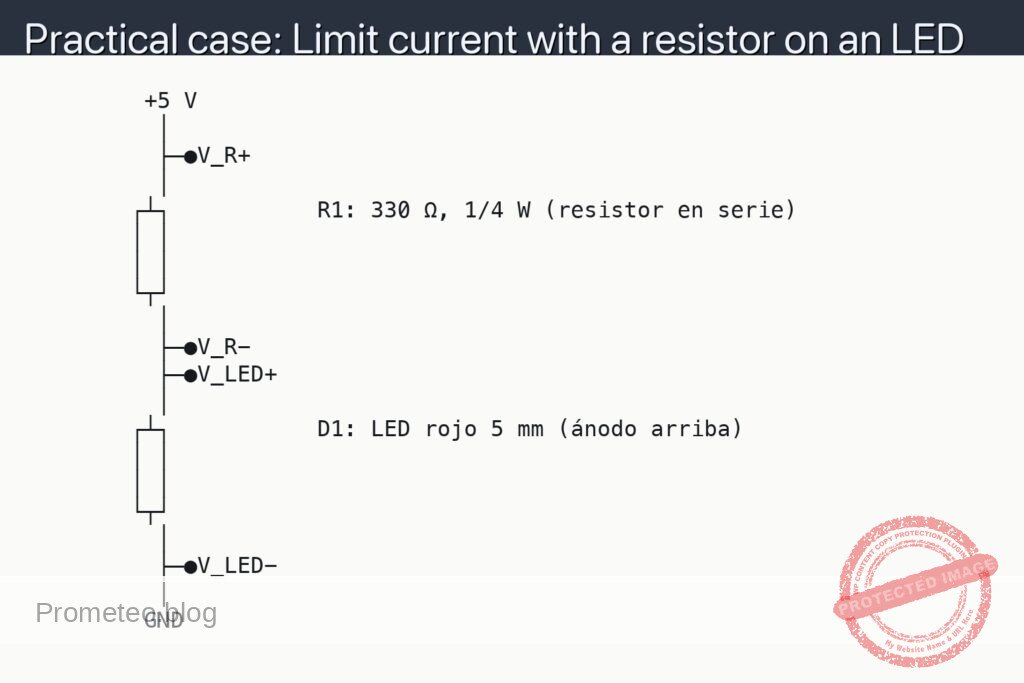
- 1 × Resistor [R1] of 10 kΩ (1/4 W is fine).
- 1 × Resistor [R2] of 5.6 kΩ (1/4 W is fine).
- 1 × Breadboard (prototyping board).
- 4 × Cables with suitable connectors (for example, 3.5 mm jack or RCA on the ends, depending on your gear).
- Several male–male jumper wires for the breadboard.
- 1 × Digital multimeter (to verify resistances and continuity).
- (Optional but highly recommended) 1 × Oscilloscope or sound card + oscilloscope software on a PC to measure waveforms.
Note: we will work with a mono signal only (one channel). For stereo, you would simply duplicate the same circuit for the left and right channels.
Wiring guide
Think of the circuit as a resistive divider for audio:
- Inputs and outputs (signal and ground):
- Connect the shield or braid of the audio source output cable to the GND of the breadboard (common ground).
- Connect the tip (signal) of the audio source output cable to the node called VIN node on the breadboard.
- Connect the shield or braid of the cable that goes to the amplifier/sound card input to the same GND on the breadboard.
-
Connect the tip (signal) of the cable that goes to the amplifier/sound card input to the node called VOUT node.
-
Resistor connections (attenuator):
- Connect the [R1] 10 kΩ resistor between VIN node and VOUT node (it will be in series with the signal).
- Connect the [R2] 5.6 kΩ resistor between VOUT node and GND (from output to ground).
With this you form a voltage divider:
VIN → [R1] → VOUT → [R2] → GND
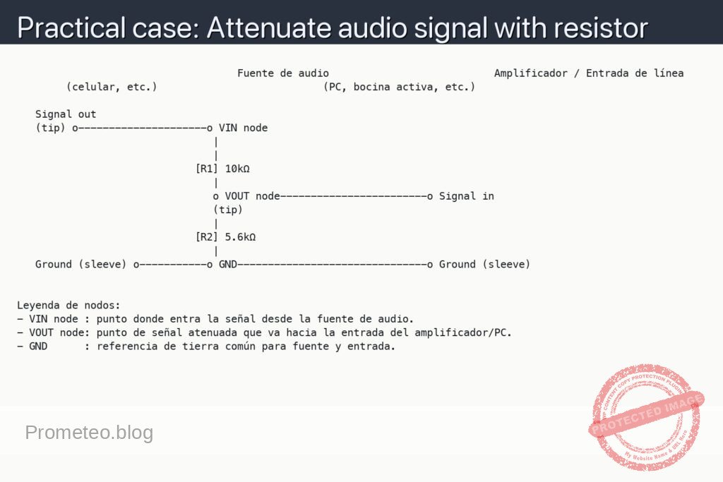
Schematic
                                    Fuente de audio                           Amplificador / Entrada de línea
        (celular, etc.)                           (PC, bocina activa, etc.)

   Signal out
   (tip) o---------------------o VIN node
                                |
                                |
                             [R1] 10kΩ
                                |
                                o VOUT node------------------------o Signal in
                                (tip)
                                |
                             [R2] 5.6kΩ
                                |
   Ground (sleeve) o-----------o GND-------------------------------o Ground (sleeve)


Leyenda de nodos:
- VIN node : punto donde entra la señal desde la fuente de audio.
- VOUT node: punto de señal atenuada que va hacia la entrada del amplificador/PC.
- GND      : referencia de tierra común para fuente y entrada.
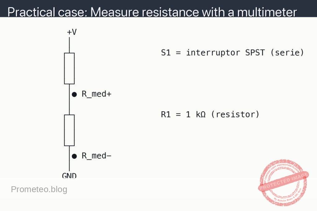
Measurements and tests
-
Resistor verification:
- Measure [R1] with the multimeter in ohmmeter mode; it should be close to 10 kΩ (for example, between 9.8 kΩ and 10.2 kΩ depending on tolerance).
- Measure [R2]; it should be close to 5.6 kΩ.
- Make sure to take these measurements with the resistors disconnected from the circuit or at least with one end lifted, so you are not measuring them in parallel with other things.
-
Basic audio test:
- Connect the cellphone or audio source, play a song or a soft tone and set the volume to a medium level.
- Compare the perceived volume by listening:
- Directly from the source to the input (without the attenuator).
- Through the attenuator.
- You should notice that the volume with the attenuator is clearly lower and that saturation distortion decreases or disappears at the input of the receiving device.
-
Measuring input and output voltage (V_in and V_out):
- Definitions:
- We will call V_in the audio voltage measured between VIN node and GND.
- We will call V_out the audio voltage measured between VOUT node and GND.
- If you have an oscilloscope:
- Connect probe CH1 between VIN node and GND and measure the signal amplitude (for example in Vpp, peak-to-peak voltage).
- Connect probe CH2 between VOUT node and GND and measure the output amplitude.
- Calculate the ratio V_out / V_in. Ideally, with the values 10 kΩ (R1) and 5.6 kΩ (R2), you will have:
- V_out ≈ V_in × [ R2 / (R1 + R2) ] ≈ V_in × [ 5.6 kΩ / (10 kΩ + 5.6 kΩ) ] ≈ V_in × 0.36
- Check that the measured ratio is reasonably close to 0.36 (it varies a bit depending on the real input/output impedances).
- If you only have a multimeter in AC mode:
- Set the multimeter to AC voltage range (VAC).
- First measure V_in between VIN node and GND with a continuous tone (for example, 1 kHz).
- Then measure V_out between VOUT node and GND under the same conditions.
- Calculate V_out / V_in. It will not be as accurate as with the oscilloscope, but it will give you an idea of the attenuation.
-
Success criteria:
- Stable attenuation: the V_out / V_in ratio remains approximately constant even if you raise or lower the source volume a bit (as long as it is not clipping).
- No audible distortion: when listening through the destination equipment (PC, powered speaker, etc.), you do not hear “clipping” or strong distortion on loud passages of the music.
- Acceptable noise: no significant additional noise is introduced (hum or loud hiss), apart from the slight noise your gear already had.
How the resistor attenuator works (simple view)
- The circuit does not amplify, it only reduces the signal level, which is why it is called a passive attenuator.
- The combination of [R1] and [R2] forms a voltage divider:
- Part of the signal “drops” across R1.
- The rest appears as an attenuated signal at VOUT.
- The ideal formula (ignoring the real source and load impedances) is:
[
V_{out} = V_{in} \cdot \frac{R_2}{R_1 + R_2}
]
With R1 = 10 kΩ and R2 = 5.6 kΩ:
[
\frac{V_{out}}{V_{in}} \approx 0{,}36
]
That is, approximately 36% of the original level (around –8.8 dB).
Common mistakes and how to avoid them
- Forgetting the common ground (GND):
- If you do not connect the shields (braids) of both cables to the same GND, you may not hear anything or there may be a lot of noise.
-
Solution: make sure the emitter and receiver GNDs are tied together.
-
Swapping R1 and R2:
- If you put R2 in series with the signal and R1 to ground, the attenuation will be different from the calculated one and it may be barely noticeable.
-
Remember: R1 in series (VIN → R1 → VOUT) and R2 to ground (VOUT → R2 → GND).
-
Using very small values (for example, hundreds of ohms):
- This can load the audio source too much and cause it to distort or prevent the device from delivering the signal correctly.
-
That is why we use values on the order of kilo-ohms (kΩ).
-
Using a very long or poorly shielded cable:
- It can introduce hum or interference.
- Keep audio cables reasonably short and preferably shielded.
Improvements and variations
- Adjustable attenuation (potentiometer):
- Instead of fixed R1 and R2, you can use a logarithmic potentiometer of, for example, 10 kΩ as a passive “volume control” between the source and the input of the equipment.
-
The principle remains the same: voltage divider.
-
Attenuator for stereo:
- Repeat exactly the same circuit for each channel:
- R1L and R2L for the left channel (L).
- R1R and R2R for the right channel (R).
-
Both channels will share the same GND reference.
-
More precise level matching:
-
If you know the input impedance of the device (for example, 10 kΩ, 47 kΩ, 100 kΩ), you can recalculate the values of R1 and R2 to obtain an exact attenuation (for example, –10 dB, –20 dB, etc.).
-
Protection against unknown loads:
- If the destination device has a low-impedance input, it may be better to use a small active buffer (a unity-gain op-amp) after the attenuator, but that is already a step beyond this basic case.
With this practical case you can now build and understand a basic passive audio attenuator with resistors, measure its effect, and adapt it to your own needs (more or less attenuation, mono or stereo, etc.).
More Practical Cases at Prometeo.blog
Find this product and/or books on this topic on Amazon
As an Amazon affiliate, I earn from qualifying purchases. If you buy through this link, you help keep this project going.
Quick quiz
More Practical Cases on Prometeo.blog

Telecommunications Electronics Engineer and Computer Engineer (official degrees in Spain).