Objective and use case
What you will build: A small LC filter (inductor + capacitor) to clean the noise from a 5 V supply that powers an Arduino, checking the improvement with an oscilloscope.
What it is used for
- Reduce the noise from a cheap switching supply before powering the Arduino.
- Filter voltage spikes produced by DC motors or relays connected to the same supply.
- Improve the stability of analog readings in sensitive sensors (e.g., potentiometer or temperature sensor).
- Decrease errors in ADC measurements caused by supply ripple.
- Obtain a dedicated filtered 5 V rail for the AREF pin or external analog modules.
Expected result
- Unfiltered input voltage with ripple of approximately 50–150 mV peak-to-peak (Vpp) measured with an oscilloscope.
- Filtered output voltage with clearly lower ripple, ideally < 30–50 mV Vpp.
- Visible difference on the oscilloscope trace between “5V_IN” and “5V_FILT” using the same vertical scale.
- Arduino running stably, without resets when connecting loads such as motors or relays.
Target audience: Electronics hobbyists and students working with Arduino; Level: Beginner–intermediate.
Architecture/flow: 5 V switching supply → “5V_IN” input → series inductor + capacitor to ground (LC filter) → “5V_FILT” output → Arduino/AREF supply, comparing on the oscilloscope before and after the filter.
Materials
- 1 × Arduino Uno (or similar 5 V board).
- 1 × 5 V switching power supply (USB charger or similar; ideally something noisy).
- 1 × Inductor (coil) of 100 µH (1 to 470 µH also works for experimenting).
- 1 × 100 µF / 10 V or higher electrolytic capacitor (for the filter).
- 1 × 100 nF (0.1 µF) ceramic capacitor (in parallel with the electrolytic, optional but recommended).
- 1 × Breadboard.
- 6–8 × Jumper wires.
- 1 × Digital multimeter.
- 1 × Oscilloscope (recommended; if you don’t have one, you can still build the circuit and use the multimeter).
- 1 × Optional noisy load: small DC motor or 5 V relay module.
- 1 × Flyback diode (for example 1N4007) if you use a motor or relay (basic protection).
Wiring guide
These connections define exactly the schematic you will see in the next section.
- Primary (unfiltered) supply
-
- Connect the positive terminal of the 5 V supply to the node called
5V_IN.
- Connect the positive terminal of the 5 V supply to the node called
-
- Connect the negative terminal of the 5 V supply to the
GNDnode (common ground for the circuit and the Arduino).
- Connect the negative terminal of the 5 V supply to the
-
LC filter
-
- Connect inductor [L1] 100 µH between node
5V_INand node5V_FILT(filtered output).
- Connect inductor [L1] 100 µH between node
-
- Connect electrolytic capacitor [C1] 100 µF between node
5V_FILTandGND(observe polarity: + to5V_FILT, − toGND).
- Connect electrolytic capacitor [C1] 100 µF between node
-
- Also connect ceramic capacitor [C2] 100 nF between node
5V_FILTandGND.
- Also connect ceramic capacitor [C2] 100 nF between node
-
Powering the Arduino with filtered voltage
-
- Connect the Arduino “5V” pin to node
5V_FILT.
- Connect the Arduino “5V” pin to node
-
- Connect an Arduino “GND” pin to node
GND.
- Connect an Arduino “GND” pin to node
-
Noisy load (optional, to see the effect of the filter)
-
- Connect one terminal of the motor or relay to node
5V_IN.
- Connect one terminal of the motor or relay to node
-
- Connect the other terminal of the motor or relay to node
GND.
- Connect the other terminal of the motor or relay to node
-
- Place diode [D1] 1N4007 in parallel with the noisy load: anode to the load node that goes to
GND, cathode to the load node that goes to5V_IN.
- Place diode [D1] 1N4007 in parallel with the noisy load: anode to the load node that goes to
-
Oscilloscope measurement points
-
- Channel 1 (CH1) of the oscilloscope: probe tip to node
5V_IN, ground clip toGND.
- Channel 1 (CH1) of the oscilloscope: probe tip to node
-
- Channel 2 (CH2) of the oscilloscope: probe tip to node
5V_FILT, ground clip toGND.
- Channel 2 (CH2) of the oscilloscope: probe tip to node
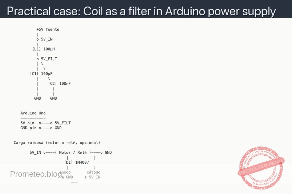
Schematic
             +5V fuente
             |
             o 5V_IN
             |
           [L1] 100µH
             |
             o 5V_FILT
             | \
             |  \
          [C1] 100µF
             |    \
             |    [C2] 100nF
             |      |
             |      |
            GND    GND


      Arduino Uno
      -----------
      5V pin  o----o 5V_FILT
      GND pin o----o GND


   Carga ruidosa (motor o relé, opcional)

          5V_IN o----( Motor / Relé )----o GND
                          |           |
                         [D1] 1N4007
                          |           |
                       ánodo       cátodo
                        a GND     a 5V_IN
                            ---
Measurements and tests
-
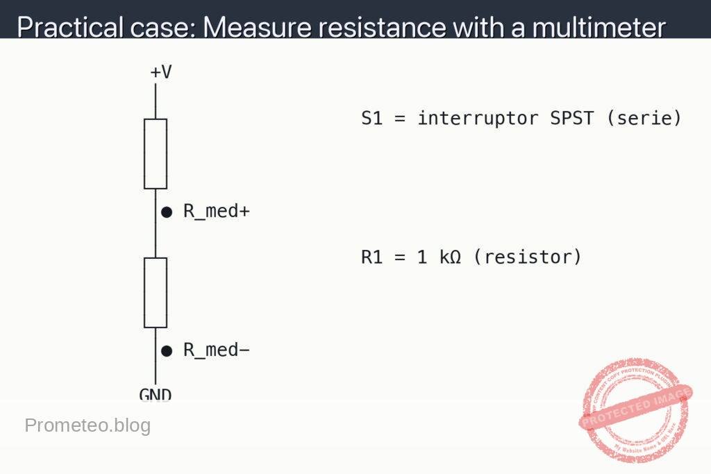
Basic voltage check with a multimeter
- Measure the voltage between
5V_INandGNDwith the multimeter in VDC mode: you should read around 5 V (the actual voltage of your supply). - Measure the voltage between
5V_FILTandGND: it should be practically the same (very small loss in the coil). - If the voltage drop between
5V_INand5V_FILTis > 0.2–0.3 V without a heavy load, check the connections or whether the inductor is heating up.
- Measure the voltage between
-
Measuring noise on the input (V_IN) with an oscilloscope
- Set the oscilloscope to AC coupling (if your model allows it) on channel CH1 and connect it to
5V_IN(tip) andGND(ground). - Set the vertical scale to something like 20 mV/div or 50 mV/div to see small ripples.
- Observe the waveform: the noise/ripple will be small “waves” or sawteeth superimposed on the 5 V voltage.
- Estimate the peak-to-peak ripple value: for example, 100 mVpp (millivolts peak-to-peak). We will call this ripple measurement “Vpp_IN”.
- Vpp_IN means “peak-to-peak voltage on the unfiltered input”, that is, the difference between the maximum and minimum value of the noise on the 5 V line.
- Set the oscilloscope to AC coupling (if your model allows it) on channel CH1 and connect it to
-
Measuring noise on the filtered output (V_FILT) with an oscilloscope
- Configure channel CH2 of the oscilloscope and connect it as before, but to
5V_FILTandGND. - Use the same vertical scale as on CH1 so you can compare directly.
- Observe the waveform: it should be noticeably “flatter” than that of
5V_IN. - Measure the peak-to-peak ripple at the filtered node (we call it “Vpp_FILT”).
- Vpp_FILT means “peak-to-peak voltage at the filtered output”; compare it with Vpp_IN. Success criterion: Vpp_FILT < 0.5 × Vpp_IN (at least 50% less ripple).
- Configure channel CH2 of the oscilloscope and connect it as before, but to
-
Test with a noisy load (motor or relay)
- With the motor or relay connected to
5V_IN, turn the load on/off (for example, with a simple switch in series with the motor). - Watch on CH1 how larger spikes appear when connecting and disconnecting the load.
- Watch on CH2 how those spikes are attenuated thanks to the LC filter.
- Check that the Arduino keeps running (a blink sketch on pin 13, for example) without resets when the load switches.
- If you have a sketch that reads an analog pin, watch in the serial monitor how the readings are more stable when powered from
5V_FILTthan if it were powered from5V_IN(you can first test “without filter” and then with the filter connected).
- With the motor or relay connected to
Basic explanation: what is the coil doing?
- The coil (inductor) [L1]:
- Opposes rapid changes in current (it doesn’t like the current to change abruptly).
- When noise tries to vary the current in the 5 V line, the coil “smooths out” that change.
- Capacitor [C1] (and [C2]):
- Provides an easy path to ground for fast voltage variations (high-frequency noise).
- For noise, the capacitor behaves almost like a short circuit to GND, “shunting” the noise.
- With the series coil and capacitor to ground, a low-pass LC filter is formed:
- High-frequency variations (noise) are attenuated.
- The low-frequency component (5 V DC voltage) passes practically unchanged.
Common mistakes
- Connecting the electrolytic capacitor backwards:
- The “−” terminal must go to
GNDand the “+” to node5V_FILT. - If reversed, the capacitor may heat up or get damaged.
- Using an inductor with too low allowable current:
- If you power many devices from
5V_FILT, make sure the inductor supports that current (check its datasheet). - Leaving the Arduino GND separate from the supply GND:
- There must be a common ground; otherwise, measurements will be wrong and the setup may not work.
- Measuring ripple with the oscilloscope improperly set:
- If the vertical scale is at 2 V/div you will not see millivolts of noise.
- Make sure you work with scales of 10–50 mV/div and AC coupling if your oscilloscope allows it.
Possible improvements and variants
- Try different L and C values:
- Inductors of 47 µH, 220 µH, 470 µH.
- Capacitors of 47 µF, 220 µF.
- Observe how Vpp_IN and Vpp_FILT change and the response when the load is switched on/off.
- Add a small series resistor (for example 1–2.2 Ω) along with L and C to form a more damped “pi” (RLC) filter.
- Filter only the analog part:
- Use
5V_FILTonly for sensors and AREF. - Leave
5V_INfor logic and digital loads (modules, relays, etc.). - Add more ceramic capacitors near the Arduino power pins and noisy modules:
- Improves local decoupling and further reduces high-frequency noise.
With this hands-on case you have seen how to use a coil as a simple supply filter and how to check its effect with objective noise measurements.
More Practical Cases on Prometeo.blog
Find this product and/or books on this topic on Amazon
As an Amazon affiliate, I earn from qualifying purchases. If you buy through this link, you help keep this project going.
Quick quiz

Telecommunications Electronics Engineer and Computer Engineer (official degrees in Spain).