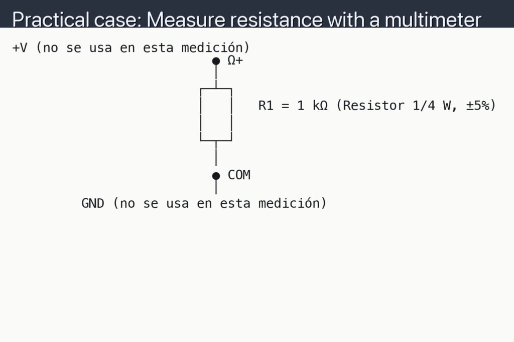
Level: Basic — Read resistor color bands and verify the value with a multimeter using a simple divider.
Materials
- 1x Resistor under test (R_UT), 4- or 5-band, unknown value
- 1x Reference resistor (R_REF), 10 kΩ ±1% (or any known, 4.7 kΩ–100 kΩ range)
- 1x Breadboard
- 1x DC power supply, 5 V (battery + regulator is fine)
- 1x Digital multimeter (DMM) with DC voltage and resistance modes
- 6x Jumper wires
- 1x Resistor color code chart (printed or on phone)
Wiring guide
- Abbreviations used in the schematic:
- V_IN: Supply voltage measurement point.
- V_MID: Midpoint between R_UT and R_REF.
- GND: Ground reference point.
- Steps:
- Plug R_UT and R_REF in series on the breadboard.
- Connect the top of R_UT to +V from the power supply.
- Connect the bottom of R_REF to GND of the power supply.
- Ensure the junction between R_UT and R_REF is accessible for probing (this is V_MID).
- Keep the DMM black probe on GND when measuring voltages; touch the red probe to V_IN or V_MID as needed.
- Double-check polarity before powering up.
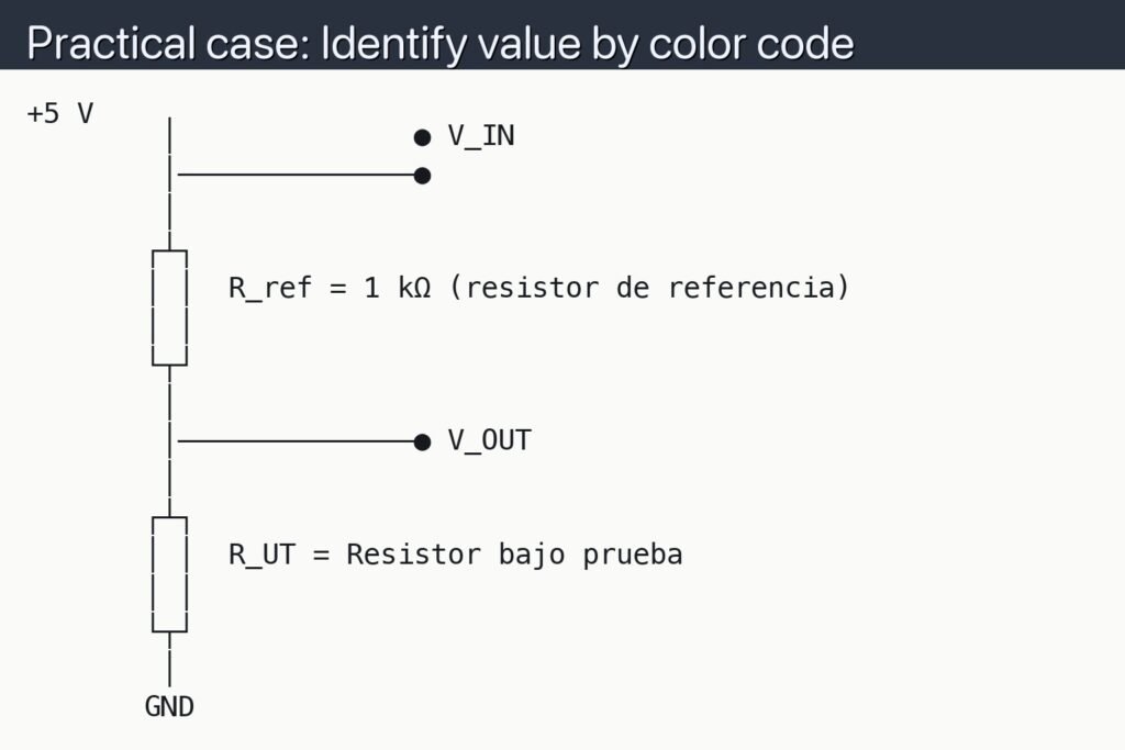
Schematic
+5 V
        │              ● V_IN
        │──────────────●
        │
       ┌┴┐
       │ │  R_ref = 1 kΩ (resistor de referencia)
       │ │
       └┬┘
        │
        │──────────────● V_OUT
        │
       ┌┴┐
       │ │  R_UT = Resistor bajo prueba
       │ │
       └┬┘
        │
       GND
Measurements and tests
-
Visual decoding (color bands):
- Identify the tolerance band (gold/silver) at the end to set reading direction.
- For 4-band: first two bands = digits, third = multiplier, fourth = tolerance.
- For 5-band: first three bands = digits, fourth = multiplier, fifth = tolerance.
- Convert colors to digits/multiplier using your chart and compute R_code and tolerance.
-
Voltage divider verification (powered):
- Set DMM to DC volts. Black probe on ● GND, red on ● V_IN; record V_IN.
- Keeping black on ● GND, move red to ● V_MID; record V_MID.
- Compute estimated resistance of R_UT (top resistor):
- R_UT_est = R_REF × (V_IN / V_MID − 1)
- Compare R_UT_est with R_code and check if the difference is within the tolerance band.
-
Optional ohmmeter cross-check (unpowered):
- Power off and disconnect the supply.
- Remove R_UT from the breadboard and measure it with the DMM in resistance mode.
- Compare with both R_code and R_UT_est.
Common mistakes
- Reading bands from the wrong end; always start from the end opposite the tolerance band.
- Using too small or too large R_REF, causing V_MID to be too close to 0 V or V_IN (reduces accuracy).
- Measuring resistance in-circuit while powered; remove power and lift one lead for a true ohms reading.
- Assuming supply is exactly 5.00 V; always measure V_IN before calculations.
Safety
- Keep supply ≤ 9 V for this exercise; higher voltages are unnecessary and risky on a breadboard.
- Never switch the DMM to ohms or current while the circuit is powered.
- Avoid touching bare conductors while probing to prevent slipping and shorting nodes.
Improvements
- Repeat with several R_UT values to practice quick mental checks of the divider formula.
- Use a tighter-tolerance R_REF (0.1%) to reduce calculation uncertainty.
- Automate calculations with a simple spreadsheet: inputs V_IN, V_MID, R_REF; output R_UT_est and percent error versus R_code.
More Practical Cases on Prometeo.blog
Find this product and/or books on this topic on Amazon
As an Amazon Associate, I earn from qualifying purchases. If you buy through this link, you help keep this project running.
Quick Quiz

Carlos Núñez Zorrilla
Electronics & Computer Engineer
Telecommunications Electronics Engineer and Computer Engineer (official degrees in Spain).