Objective and use case
What you’ll build: In this practical case, you will learn how to safely drive a red LED using a series resistor from a 5V DC supply. This guide is designed for beginners to understand basic electronic principles.
Why it matters / Use cases
- Understanding current limiting to prevent LED damage in hobby electronics projects.
- Applying basic circuit design principles in educational settings or DIY projects.
- Using series resistors to control brightness in LED applications.
- Learning to measure voltage and current in circuits with a digital multimeter.
- Implementing safe practices in electronics to avoid short circuits and component failures.
Expected outcome
- LED operates at approximately 20 mA current without exceeding its ratings.
- Measured voltage across the LED should be around 2.0 V.
- Voltage drop across the resistor (R1) will be approximately 3.0 V.
- Ability to calculate current using the formula I_LED = V_R / R1, confirming proper circuit function.
- Understanding of how to safely disconnect and reconnect power while working on circuits.
Audience: Beginners; Level: Basic
Architecture/flow: Series resistor limiting current from a 5V DC supply to an LED.
Materials
- 1 × Red LED (forward voltage ≈ 2.0 V) [Materials #1]
- 1 × Resistor 330 Ω, 1/4 W (series limiter) [Materials #2]
- 1 × DC power supply, 5 V (current‑limited if available) [Materials #3]
- 1 × Digital multimeter (DMM) [Materials #4]
- 1 × Breadboard and a few jumper wires [Materials #5]
Wiring guide
- Disconnect power while wiring.
- Place the LED on the breadboard. Identify polarity: the anode is the longer lead; the cathode side usually has a flat edge on the LED body.
- Connect the resistor (R1) in series with the LED:
- +V from the DC supply goes to one end of R1.
- The other end of R1 goes to the LED anode.
- The LED cathode goes to GND.
- Set the power supply to +5 V. If it has current limit, set ~20 mA max.
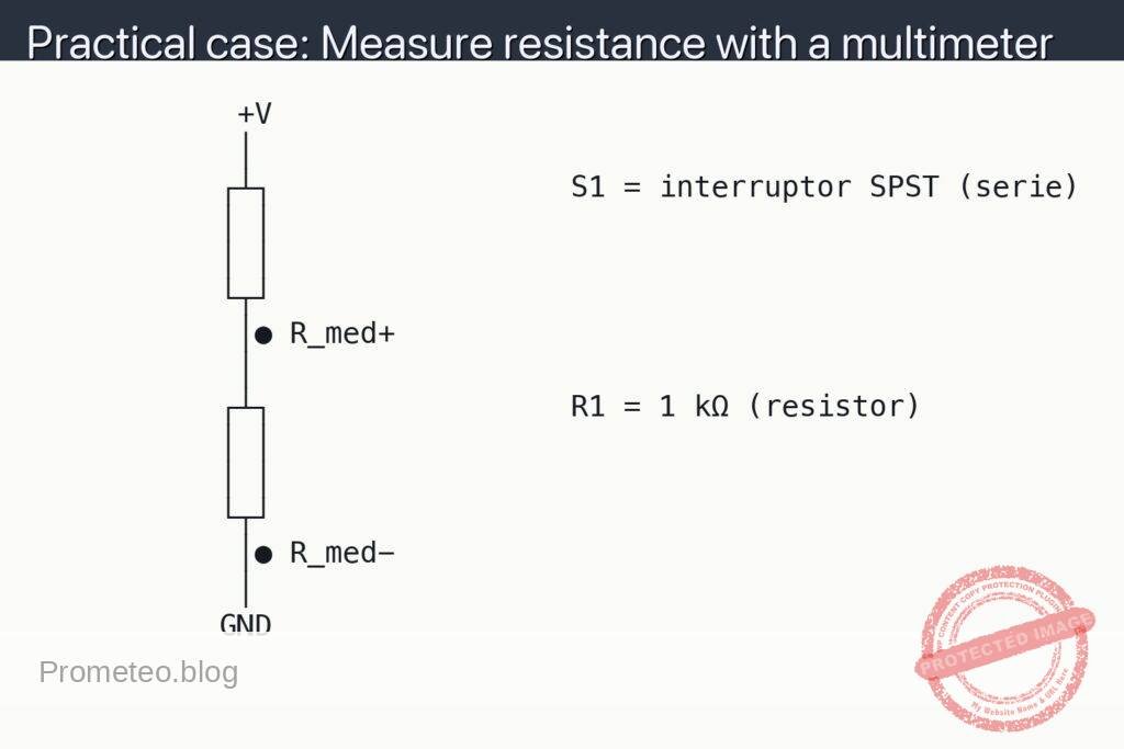
- Abbreviations used in the schematic and measurements:
- V_R+, V_R−: positive and negative probe points to measure the voltage across the resistor R1.
- V_LED+, V_LED−: positive and negative probe points to measure the voltage across the LED.
- I_LED: LED current; compute as I_LED = V_R / R1, where V_R = V_R+ − V_R− and R1 = 330 Ω.
- Do not insert the ammeter in series unless instructed; you can compute current from V_R to avoid opening the circuit.
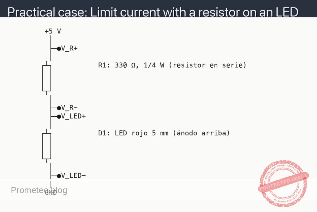
Schematic
         +5 V
          │
          ├─●V_R+
          │
        ┌┴┐           R1: 330 Ω, 1/4 W (resistor en serie)
        │ │
        │ │
        └┬┘
          │
          ├─●V_R-
          ├─●V_LED+
          │
        ┌┴┐           D1: LED rojo 5 mm (ánodo arriba)
        │ │
        │ │
        └┬┘
          │
          ├─●V_LED-
          │
         GND
Measurements and tests
-
Before powering on:
- Verify series order: +V → R1 → LED (anode) → LED (cathode) → GND.
- Confirm the resistor value is 330 Ω (measure with DMM in resistance mode if unsure).
- Ensure the LED polarity is correct.
-
Power up and basic check:
- Apply +5 V. The LED should light steadily (not flicker).
-
Measure V_R (resistor voltage):
- Place DMM in DC voltage mode.
- Touch the red probe to the dot labeled V_R+ and the black probe to V_R−.
- Note V_R. Expected ≈ 3.0 V (since 5 V − ~2.0 V_LED ≈ 3.0 V).
-
Measure V_LED (LED voltage):
- Keep DMM in DC voltage mode.
- Touch the red probe to V_LED+ and the black probe to V_LED−.
- Note V_LED. Expected ≈ 1.8–2.2 V for a typical red LED.
-
Compute I_LED (LED current):
- Use I_LED = V_R / R1. With V_R ≈ 3.0 V and R1 = 330 Ω, I_LED ≈ 9.1 mA.
- Check resistor power: P_R = I_LED² × R1 ≈ (0.0091 A)² × 330 Ω ≈ 0.027 W (well below 1/4 W).
-
Optional direct current check (advanced):
- Power off first. Move the DMM to current mode and into the correct jack.
- Break the connection between R1 and LED anode; insert the ammeter in series at that point.
- Power on and read I_LED directly; it should match the computed value within meter tolerance.
- Power off and restore the original wiring after the test.
How to choose the resistor (rule of thumb)
- Target current for standard 5 mm red LED: 5–15 mA for long life.
- Use R = (V_SUPPLY − V_F_LED) / I_TARGET.
- Example at 5 V: R ≈ (5 V − 2.0 V) / 0.010 A = 300 Ω; the next standard value up is 330 Ω.
Common mistakes
- Reversing LED polarity (no light or very dim).
- Omitting the series resistor (can damage the LED and supply).
- Using too small a resistor (excessive current, LED overheats).
- DMM still in current mode when measuring voltage (blows meter fuse).
Safety notes
- Set current limiting on the bench supply if available.
- Never touch probes together while across the supply; avoid short circuits.
- Power off before changing wiring or moving the ammeter into the circuit.
Possible improvements
- Add a switch in series to turn the LED on/off cleanly.
- Try other LED colors and update R accordingly (green/blue LEDs have higher V_F).
- Use a trimmer potentiometer in series to experiment with brightness vs. current.
More Practical Cases on Prometeo.blog
Find this product and/or books on this topic on Amazon
As an Amazon Associate, I earn from qualifying purchases. If you buy through this link, you help keep this project running.
Quick Quiz

Telecommunications Electronics Engineer and Computer Engineer (official degrees in Spain).