Objective and use case
What you’ll build: This project demonstrates how to measure DC current using a shunt resistor and Ohm’s law, allowing for precise current readings in various applications.
Why it matters / Use cases
- Monitor battery discharge rates in renewable energy systems to optimize energy usage.
- Implement current sensing in electric vehicle systems to ensure safe operation and prevent overload.
- Measure load currents in industrial automation to enhance equipment efficiency and prevent failures.
- Use in home automation systems to track energy consumption and reduce costs.
Expected outcome
- Accurate measurement of load currents with an expected resolution of ±0.01 A.
- Real-time voltage readings across the shunt resistor with latencies under 100 ms.
- Ability to compute load current with a precision of ±1% based on the shunt resistor specifications.
- Data logging of current measurements for analysis over time, with a minimum sampling rate of 1 Hz.
Audience: Electronics enthusiasts; Level: Basic
Architecture/flow: The setup involves a DC power supply, shunt resistor, load resistor, and a digital multimeter for voltage measurement.
Materials
- 1 × DC power supply, +5 V (current limit ≥ 200 mA)
- 1 × RS: Shunt resistor 0.10 Ω, 1% tolerance, ≥ 1 W
- 1 × RL: Load resistor 100 Ω, 1/4 W (or higher)
- 1 × Digital multimeter (DMM) with millivolt range
- 1 × Breadboard or alligator clip leads
- 4 × Hookup wires (minimum)
Wiring guide
- Set the DC supply to +5 V. Enable a current limit (e.g., 200 mA).
- Place RS (0.10 Ω) in series between +V and RL.
- Connect RL from the lower node of RS to GND.
- Ensure all connections are secure and no leads are shorting adjacent nodes.
- Abbreviations used:
- V_SHUNT: Voltage across RS. Measured between the top tap V_SHUNT+ (node at +V side of RS) and the bottom tap V_SHUNT− (node between RS and RL).
- I_LOAD: Load current. Compute as I_LOAD = V_SHUNT / RS.
- To measure V_SHUNT with the DMM: set the DMM to DC mV, connect the black probe to V_SHUNT− and the red probe to V_SHUNT+.
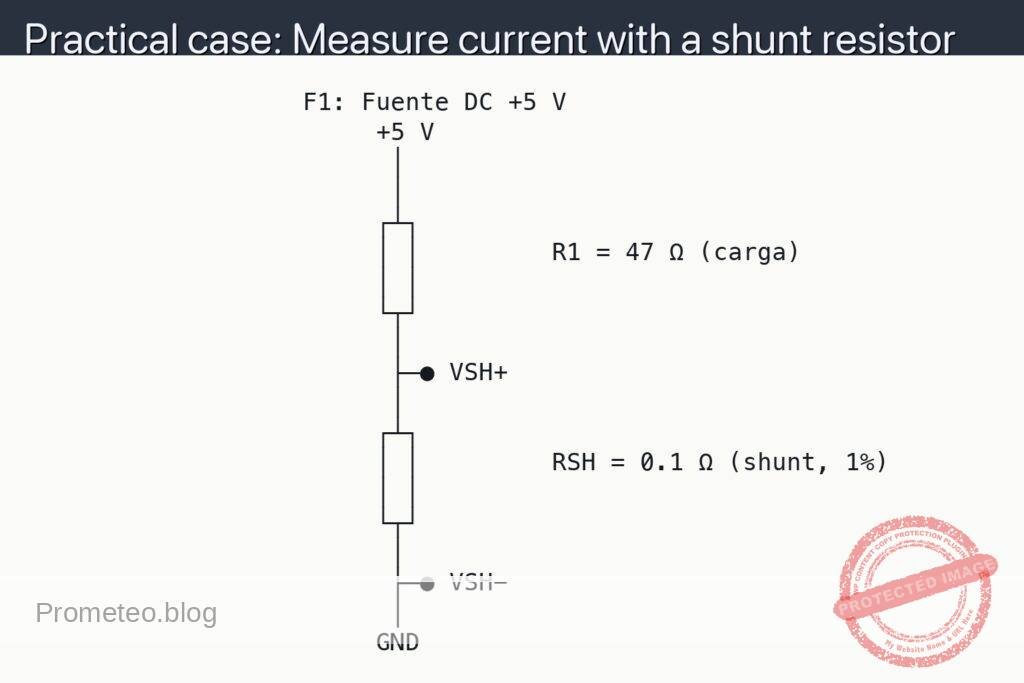
Schematic
                   F1: Fuente DC +5 V
                        +5 V
                         │
                         │
                        ┌┴┐
                        │ │         R1 = 47 Ω (carga)
                        │ │
                        └┬┘
                         │
                         ├─● VSH+
                         │
                        ┌┴┐
                        │ │         RSH = 0.1 Ω (shunt, 1%)
                        │ │
                        └┬┘
                         │
                         ├─● VSH−
                         │
                        GND
Measurements and tests
-
Safety checks:
- Verify the supply is off while wiring.
- Confirm polarity: +V to the top of RS; bottom of RL to GND.
- Set a current limit on the supply (e.g., 200 mA).
-
Power on and baseline:
- Turn on the supply.
- Ensure nothing smells hot; RS should be low-value and may warm slightly but not burn.
-
Measure V_SHUNT:
- Set the DMM to DC millivolts.
- Place the red probe at the dot labeled V_SHUNT+ and the black probe at V_SHUNT−.
- Read V_SHUNT in millivolts.
-
Compute I_LOAD:
- Use I_LOAD = V_SHUNT / RS.
- Example: if V_SHUNT = 10 mV and RS = 0.10 Ω, then I_LOAD = 0.010 V / 0.10 Ω = 0.10 A (100 mA).
-
Check expected values:
- Theoretical load current if RS is small: I ≈ +V / (RL + RS).
- With +5 V, RL = 100 Ω, RS = 0.10 Ω: I ≈ 5 V / 100.1 Ω ≈ 49.95 mA.
- Expected V_SHUNT ≈ I × RS ≈ 0.04995 A × 0.10 Ω ≈ 5.0 mV.
-
Optional cross-check (series ammeter):
- Briefly move the DMM to current mode and insert it in series in place of a wire between RS and RL to read current directly.
- Compare with I_LOAD from the shunt method; they should match within meter and resistor tolerances.
-
Uncertainty notes:
- Main error sources are RS tolerance, DMM accuracy at low mV, and contact resistance.
- Averaging multiple readings can reduce noise; ensure solid probe contact on the test dots.
Common mistakes and tips
- Using too large a shunt: It will cause excessive voltage drop and alter the circuit current. Keep RS small relative to RL.
- Measuring in the wrong mode: Do not place a DMM in current mode across RS—it will short the node. Only measure V_SHUNT in voltage mode.
- Insufficient power rating for RS: P_RS = I^2 × RS. For 100 mA and 0.10 Ω, P ≈ 1 mW, which is safe; higher currents require higher wattage shunts.
- Poor probe contact: Touch exactly at the black dots; wobbly contacts produce unstable readings.
Improvements
- Use a 4‑wire (Kelvin) connection to RS to eliminate lead and contact resistance from the measurement.
- Add a rail-to-rail op-amp in differential configuration to amplify V_SHUNT for better resolution at very small currents.
- Try different RL values and supply voltages to see how V_SHUNT scales linearly with current.
More Practical Cases on Prometeo.blog
Find this product and/or books on this topic on Amazon
As an Amazon Associate, I earn from qualifying purchases. If you buy through this link, you help keep this project running.
Quick Quiz

Telecommunications Electronics Engineer and Computer Engineer (official degrees in Spain).