Objective and use case
What you’ll build: In this practical case, you’ll learn how to accurately measure the resistance of a resistor using a digital multimeter (DMM) and verify its tolerance. This hands-on guide is designed for beginners.
Why it matters / Use cases
- Understanding resistor values is crucial for designing circuits, ensuring components function as intended.
- Verifying tolerance helps in selecting the right resistors for precision applications in audio equipment or sensor circuits.
- Learning to use a DMM builds foundational skills for troubleshooting and testing electronic devices.
- Measuring resistance in various components aids in diagnosing faults in electronic circuits.
- Hands-on experience with a DMM prepares you for more advanced electronics projects and repairs.
Expected outcome
- Accurate resistance readings within ±5% of the resistor’s specified value.
- Ability to identify and interpret tolerance levels (1% or 5%) of resistors.
- Familiarity with using a DMM in resistance mode, including proper lead connections.
- Understanding of the importance of isolating components before measurement to avoid erroneous readings.
- Improved confidence in handling electronic components and tools.
Audience: Beginners; Level: Basic
Architecture/flow: Measure resistance using a digital multimeter (DMM) by connecting test leads to a resistor in isolation.
Materials
- 1× Resistor, e.g., 1 kΩ, 1% or 5% (R1, the RUT)
- 1× Digital multimeter with Ω (resistance) mode (DMM)
- 2× Multimeter test leads (red and black)
- 1× Breadboard or small insulating surface (optional)
- 2× Mini grabber or alligator clips (optional, for steadier contact)
Wiring guide
- Ensure the resistor is isolated: remove it from any powered circuit or lift at least one lead from the board so it is not connected to other components (in-circuit readings can be wrong).
- Place R1 (the resistor under test, RUT) on a breadboard row or on an insulating surface so both leads are accessible.
- Set the DMM to resistance (Ω). If manual-ranging, choose a range higher than the expected value (e.g., 20 kΩ to measure ~1 kΩ).
- Connect the red lead to the DMM’s Ω/V jack and the black lead to COM.
- Touch the red probe to the top terminal labeled Ω+ in the schematic, and the black probe to the bottom terminal labeled Ω−.
- Hold steady contact until the reading stabilizes. If the display shows “OL” or over-range, select a higher range.
- Abbreviations used:
- DMM = Digital Multimeter.
- RUT = Resistor Under Test (R1).
- Ω+ = Point where the red (positive) ohmmeter lead touches.
- Ω− = Point where the black (common) ohmmeter lead touches.
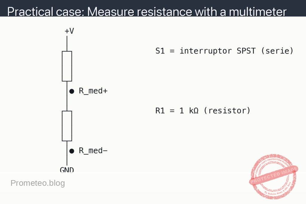
Schematic
            +V
            │
           ┌┴┐                 S1 = interruptor SPST (serie)
           │ │
           │ │
           └┬┘
            │● R_med+
            │
           ┌┴┐                 R1 = 1 kΩ (resistor)
           │ │
           │ │
           └┬┘
            │● R_med−
            │
           GND
Measurements and tests
- Preparation:
- Zero/leads check: briefly short red and black probes together in Ω mode; the DMM should read near 0 Ω.
- Visual estimate: read the resistor color code (e.g., brown–black–red = 1 kΩ; gold = ±5%) to predict the expected value.
- Main measurement:
- Measure between Ω+ and Ω− as shown. Record R_meas (the displayed resistance).
- Compare R_meas to the nominal value and tolerance band. For a 1 kΩ ±5% resistor, acceptable span is 950–1050 Ω.
- Cross-checks:
- If using clip leads, remeasure with direct probe contact to rule out clip contact resistance.
- Reverse probes (swap Ω+ and Ω−); resistance should be identical (resistors are non-polarized).
- In-circuit caution (only if you must measure without removing R1):
- Power OFF and discharge capacitors first.
- Measure; if R_meas is unexpectedly low, parallel paths in the circuit are affecting the reading. Isolate by lifting one lead of R1 and remeasure.
Common mistakes
- Measuring while the circuit is powered: the DMM’s ohmmeter injects a small test current; external voltages can damage the meter or give false readings.
- Not isolating the resistor: parallel components make the apparent resistance lower than the true value.
- Wrong DMM jack or range: leads in the current jack or too-low range cause “OL” or nonsense values.
- Poor probe contact: touching paint, oxidation, or the resistor body rather than the metal lead increases measured resistance.
Safety tips
- Always power down and disconnect power sources before switching the DMM to Ω mode.
- Discharge capacitors; stored charge can bias the measurement or harm the meter.
- Do not measure resistance on live mains circuits.
Extensions and improvements
- Tolerance verification: measure multiple units of the same value to observe distribution within the tolerance band.
- Temperature effect: warm the resistor gently between fingers and watch small changes in R_meas (temperature coefficient).
- Series/parallel sanity check: connect two known resistors and verify expected combined resistance before returning to in-circuit work.
More Practical Cases on Prometeo.blog
Find this product and/or books on this topic on Amazon
As an Amazon Associate, I earn from qualifying purchases. If you buy through this link, you help keep this project running.
Quick Quiz

Carlos Núñez Zorrilla
Electronics & Computer Engineer
Telecommunications Electronics Engineer and Computer Engineer (official degrees in Spain).