Level: Basic — Measure a resistor accurately and safely using a multimeter.
Materials
- 1x Resistor R1 (e.g., 1 kΩ, 1/4 W, ±5%)
- 1x Digital multimeter with resistance (Ω) mode
- 2x Multimeter probes (red and black, typically included)
- 1x Breadboard or two jumper wires to hold the resistor (optional)
- 1x Tweezers (optional; helpful for small parts)
Wiring guide
- Power safety:
- Ensure the resistor is NOT connected to any powered circuit. If it was, disconnect power and discharge nearby capacitors before measuring.
- Mount the resistor:
- Insert R1 into a breadboard or hold it by its insulated body so both leads are accessible.
- Multimeter setup:
- Set the multimeter to resistance (Ω) mode. If manual ranging, choose a range above the expected value.
- Abbreviations used:
- DMM_Ω+ = red probe of the digital multimeter in ohms mode.
- DMM_Ω− = black probe of the digital multimeter in ohms mode.
- Probe placement:
- Touch DMM_Ω+ to the upper lead of R1 and DMM_Ω− to the lower lead, exactly at the black dots shown in the schematic.
- Avoid touching the bare metal of the resistor leads with your fingers during the reading to prevent parallel resistance paths.
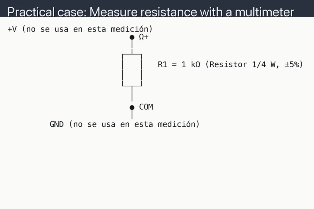
Schematic
+V (no se usa en esta medición)
                          ● Ω+
                          │
                        ┌─┴─┐
                        │   │   R1 = 1 kΩ (Resistor 1/4 W, ±5%)
                        │   │
                        └─┬─┘
                          │
                          ● COM
                          │
         GND (no se usa en esta medición)
Measurements and tests
-
Basic measurement:
- Set the meter to Ω mode and connect DMM_Ω+ (red) and DMM_Ω− (black) to the black dots as in the schematic.
- Read the displayed resistance. Call this R_meas (measured resistance).
-
Compare to nominal value:
- Decode R1’s color bands (or read its marking) to get R_nom (nominal resistance) and tolerance tol%.
- Verify R_meas is within R_nom ± tol%. Example for 1 kΩ ±5%: acceptable range is 950 Ω to 1050 Ω.
-
Lead resistance compensation (for low-ohm parts):
- Short the probes together; record R_leads (lead/probe resistance).
- Compute R_true = R_meas − R_leads. Use R_true for comparison.
-
Stability and contact check:
- Reverse the probes (swap DMM_Ω+ and DMM_Ω−) and re-measure; ideal resistors read the same both ways.
- If the reading jumps or drifts, clean the leads or improve probe contact pressure.
-
In-circuit caution:
- Measuring R1 while it’s soldered on a PCB can read lower due to parallel paths.
- If R_meas is unexpectedly low, lift one lead of R1 from the circuit and remeasure isolated.
Common mistakes and safety
- Measuring resistance on a powered circuit can damage the multimeter and give false readings. Always remove power and discharge capacitors.
- Holding the metal leads with fingers during measurement can lower R_meas. Grip the body or use tweezers.
- Using the wrong range can cause “OL” or slow autoranging. Select a manual range just above the expected value if possible.
- For hot components, readings may drift; allow parts to cool to room temperature before measuring.
Improvements and extensions
- For very low resistances (<1 Ω), use a 4-wire (Kelvin) measurement DMM to eliminate lead resistance errors.
- Log multiple readings and average them to reduce noise; note ambient temperature, as resistance changes with temperature (TCR).
More Practical Cases on Prometeo.blog
Find this product and/or books on this topic on Amazon
As an Amazon Associate, I earn from qualifying purchases. If you buy through this link, you help keep this project running.
Quick Quiz

Carlos Núñez Zorrilla
Electronics & Computer Engineer
Telecommunications Electronics Engineer and Computer Engineer (official degrees in Spain).