Objective and use case
What you will build: A very simple circuit where a small DC motor is powered by a battery and its speed is limited using only a series resistor. You will see how speed, noise, and current change when you modify the resistor value.
What it is used for
- Reducing the speed of a toy DC motor so it doesn’t spin so fast or feel aggressive to the touch.
- Reducing the noise of a motor in scale models (cars, trains, dioramas) without changing the motor.
- Preventing a motor from being stressed when a fresh battery with a higher-than-usual voltage is used.
- Quickly testing different speeds by changing only the resistor value, without complex electronics.
- Experimentally illustrating how a series resistor reduces the current and therefore the speed of a DC motor.
Expected result
- Motor speed without resistor (battery directly) ≈ 100% as a subjective reference.
- Motor speed with series resistor reduced to ≈ 40–70% (the difference is clearly noticeable by eye and ear).
- Motor current without resistor ≈ I_MOTOR_SIN_R (typically 200–400 mA depending on the motor and the battery used).
- Motor current with resistor ≈ 30–60% of I_MOTOR_SIN_R, measured with a multimeter in series.
- Voltage at the motor (V_MOTOR) with resistor clearly lower than the battery voltage (for example, from 1.5 V of the battery to ~0.7–1.0 V at the motor, depending on the resistor and load).
Target audience: Beginner electronics hobbyists; Level: introductory, no prior circuit design knowledge required.
Architecture/flow: Battery → series resistor → DC motor → return to the battery; first the behavior without resistor is measured (reference current and speed) and then with one or more resistor values to compare speed, noise, current, and voltage at the motor.
Materials
- 1 × Small DC motor (3–6 V typical from toys or mini fans).
- 1 × Power resistor 10 Ω, 2 W (or a nearby value between 5–22 Ω, minimum 1 W).
- 1 × 3–6 V cell or battery (for example, 2×AA or a 9 V battery if the motor supports it).
- 1 × Battery holder or clip.
- 2 × Alligator clip leads (or several breadboard wires).
- 1 × Digital multimeter (able to measure DC voltage and DC current up to at least 1 A).
- 1 × Simple switch (optional, it can be replaced by connecting and disconnecting a wire).
Wiring guide
- Connect the positive terminal of the battery (+) to one end of the resistor [R1] 10 Ω.
- Connect the other end of the resistor [R1] 10 Ω to the positive terminal of the DC motor [M1].
- Connect the negative terminal of the DC motor [M1] to the negative terminal (–) of the battery (GND).
- If you use a switch:
- Connect the switch [S1] in series between the battery (+) and the resistor, or between the resistor and the motor (choose just one place in series).
- Prepare two measurement points:
- Node VA: junction between battery (+) and resistor [R1] (before the resistor).
- Node VB: junction between resistor [R1] and motor [M1] (after the resistor, before the motor).
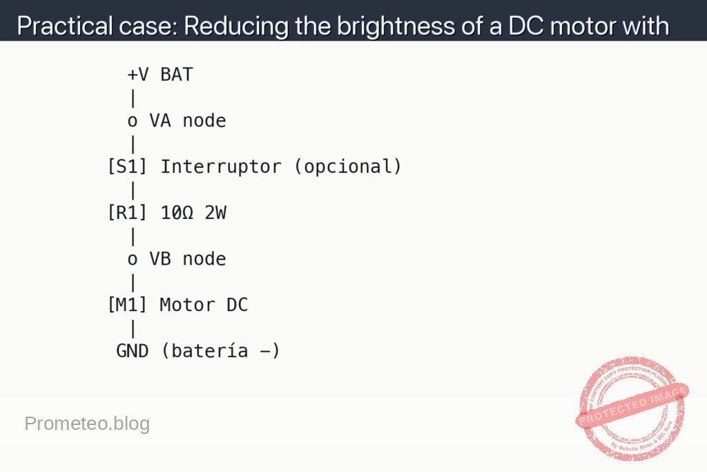
Schematic
          +V BAT
          |
          o VA node
          |
        [S1] Interruptor (opcional)
          |
        [R1] 10Ω 2W
          |
          o VB node
          |
        [M1] Motor DC
          |
         GND (batería -)
Measurements and tests
-
Verify basic operation:
- Disconnect the resistor and connect the motor directly between +V BAT and GND.
- Observe the motor speed (visual/auditory “100%” reference).
- Go back to the connection with the series resistor as in the schematic.
- Check that the motor is still spinning, but at a lower speed.
-
Measure motor voltage (V_MOTOR):
- V_MOTOR means “voltage between the motor terminals”.
- Set the multimeter to DC voltage mode (V⎓).
- Place the red probe on the positive terminal of the motor [M1] (node VB).
- Place the black probe on the negative terminal of the motor [M1] (GND).
- Write down V_MOTOR with resistor and compare it with the no-load battery voltage (V_BAT).
-
Measure voltage across the resistor (V_R):
- V_R means “voltage across the ends of resistor R1”.
- Keep the multimeter in DC voltage mode.
- Red probe on VA node (before the resistor).
- Black probe on VB node (after the resistor).
- Write down V_R with the motor spinning; it should be V_R = V_BAT − V_MOTOR (approx.).
-
Measure motor current (I_MOTOR):
- I_MOTOR means “current flowing through the motor and the resistor”.
- Switch the multimeter to DC current mode (A⎓) and use the appropriate input (mA or A, depending on the range).
- Open the circuit between the battery (+) and resistor [R1].
- Connect the red probe of the multimeter to the positive terminal of the battery (+).
- Connect the black probe of the multimeter to the free end of resistor [R1] (VA node now goes through the multimeter).
- Turn on the circuit (close [S1] if you use it) and read I_MOTOR.
- Repeat the measurement also without the resistor (motor directly on the battery) to obtain I_MOTOR_SIN_R and compare.
-
Check resistance–speed relationship:
- If you have several resistors (for example, 4.7 Ω, 10 Ω, 22 Ω), repeat the V_MOTOR and I_MOTOR measurements for each value.
- Observe:
- The higher the resistance, the lower the I_MOTOR.
- The lower the I_MOTOR, the lower the V_MOTOR and the lower the motor speed.
- Write down in a small table: R, V_MOTOR, I_MOTOR, observed speed (fast/medium/slow).
Common mistakes
-
Using a resistor with too little power rating:
- A motor can draw hundreds of mA; the resistor dissipates power P = I²·R.
- If R = 10 Ω and I = 0.3 A, P ≈ 0.9 W; a 1/4 W resistor will overheat and may burn.
- Use resistors of at least 1 W, preferably 2 W for this kind of test.
-
Connecting the resistor in parallel with the motor:
- This barely reduces the motor speed and only wastes current.
- The resistor must go in series with the motor, in the only current path.
-
Confusing voltage measurement with current measurement:
- Voltage: the multimeter is connected in parallel (one probe on each side of the component).
- Current: the multimeter is connected in series (open the circuit and the multimeter “acts as a wire”).
-
Powering a low-voltage motor with a battery that is too high without a resistor:
- For example, a 3 V motor directly on a 9 V battery: it may heat up, make strange noises, or get damaged.
- If you notice the motor heating up a lot or producing a smell, stop the experiment and reduce the voltage or increase R.
Safety and good practices
- Do not touch the motor shaft when it is spinning at high speed; it can catch on clothing or hair.
- If the resistor gets so hot that you cannot touch it comfortably, disconnect the power and let it cool down.
- Do not leave the setup powered unattended, especially with 9 V batteries or large packs.
- Always check the battery polarity before turning on the circuit.
Possible improvements
- Replace the fixed resistor with a power potentiometer (for example, 100 Ω, 2 W) to have continuous speed control.
- Add a fixed switch [S1] for on/off without disconnecting wires.
- Use a MOSFET with PWM (pulse-width modulation) instead of a resistor, to improve efficiency and have better speed control.
- Add a small optical tachometer or a Hall sensor to measure RPM and relate them to V_MOTOR and I_MOTOR.
More Practical Cases on Prometeo.blog
Find this product and/or books on this topic on Amazon
As an Amazon affiliate, I earn from qualifying purchases. If you buy through this link, you help keep this project going.
Quick quiz

Telecommunications Electronics Engineer and Computer Engineer (official degrees in Spain).