Objective and use case
What you will build: A small circuit with a capacitor in series/parallel with a mini LED lamp and batteries to smooth brief power interruptions. You will see how the capacitor acts as an energy “reserve”, preventing abrupt flickering.
What it is used for
- Reducing the flicker of a mini LED flashlight when you move the switch or when it makes poor contact.
- Smoothing brightness changes when the batteries are partially discharged or their voltage drops when turning on.
- Avoiding micro power cuts due to false contacts in the battery holder or loose connections.
- Simulating a smoother on/off of a small decorative “LED candle”-type lamp.
- Experimenting in a practical way with the effect of a capacitor as a filter/energy storage in direct current.
Expected result
- The LED maintains visible brightness for ≈0.2–0.5 s when you quickly open and close the switch, instead of turning off abruptly.
- The voltage across the LED (V_LED) changes over tens of milliseconds: you will see a slower rise/fall on an oscilloscope or logger.
- The current through the LED (I_LED) decreases progressively when the power is cut, instead of dropping instantly to 0.
- The discharge time of the capacitor (t_discharge) can be estimated by measuring how long the LED takes to go from normal brightness to almost off.
Target audience: Basic electronics hobbyists, educators and secondary school/VET students; Level: Beginner–intermediate (first projects with discrete components).
Architecture/flow: Battery supply → switch → current-limiting resistor + LED → capacitor in parallel with LED+resistor; sudden changes in battery voltage are damped by charging/discharging the capacitor, which maintains the current through the LED for a few hundred milliseconds.
Materials
- 1 × 3 V to 5 V source (for example, 2 AA cells in series or a regulated lab power supply).
- 1 × White LED (or any color).
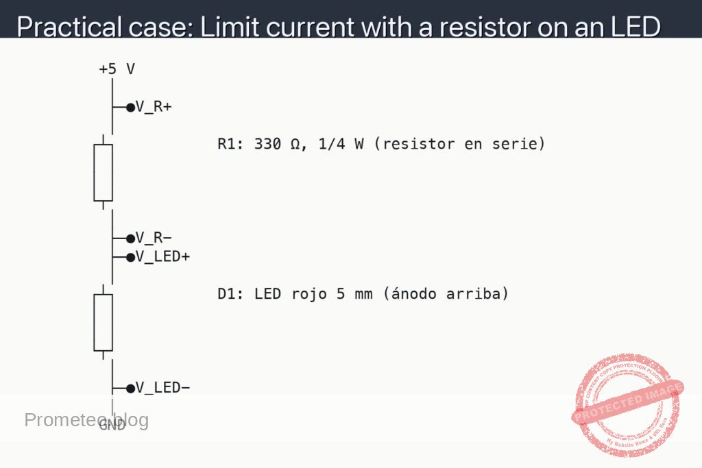
- 1 × [R1] Current-limiting resistor for the LED:
- 220 Ω for 5 V
- 100 Ω for 3 V (if you use only 2×AA, for example).
- 1 × [C1] 470 µF to 1000 µF electrolytic capacitor, 10 V or more (polarized).
- 1 × Simple switch (SPST) or normally open pushbutton.
- 1 × Breadboard.
- 4–6 × Jumper wires (male-male).
- 1 × Digital multimeter (to measure voltages and, optionally, current).
In the text I will use 5 V and R1 = 220 Ω as an example. If you use 3 V, just adjust the value of R1 as indicated.
Wiring guide
- Connect the positive terminal of the 5 V supply to the first contact of the switch.
- Connect the second contact of the switch to the left end of [R1] 220 Ω.
- Connect the right end of [R1] 220 Ω to the VA node, which will be the common point of the mini lamp.
- Connect the anode (long lead) of the LED to node VA.
- Connect the cathode (short lead) of the LED to GND (negative of the supply).
- Connect the positive terminal of [C1] 1000 µF to node VA.
- Connect the negative terminal of [C1] 1000 µF to GND.
- Connect the negative of the supply (0 V) to the GND rail of the breadboard.
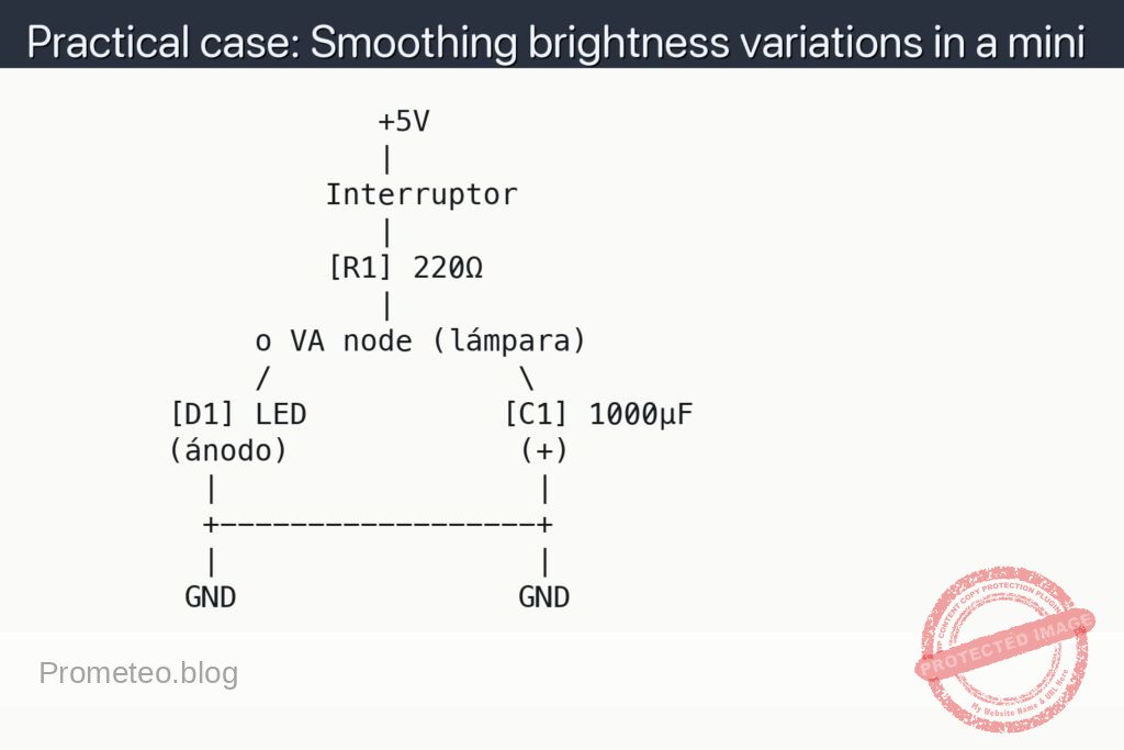
This VA node is where you will see the effect of the capacitor: there the resistor coming from the supply, the LED, and the capacitor in parallel with the LED are all connected.
Schematic
                    +5V
                    |
                 Interruptor
                    |
                 [R1] 220Ω
                    |
             o VA node (lámpara)
             /              \
        [D1] LED           [C1] 1000µF
        (ánodo)             (+)
          |                  |
          +------------------+
          |                  |
         GND                GND
Measurements and tests
-
Basic operation check:
- Close the switch: the LED should light up with normal brightness.
- Open the switch: the LED should turn off smoothly, not instantly; it should take a fraction of a second.
- Repeat several times: observe whether small flickers or very brief cuts that you would have without the capacitor disappear.
-
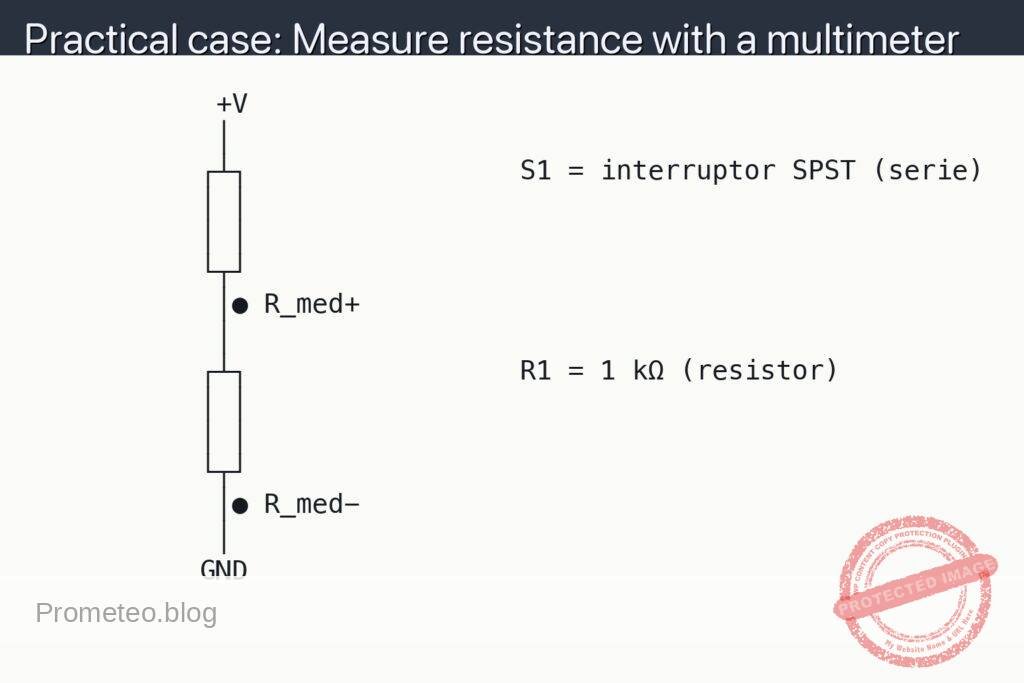
Measuring the voltage on the LED (V_LED):
- V_LED means “voltage between the anode and the cathode of the LED”.
- Place the black probe of the multimeter on GND and the red probe on the LED anode (VA node).
- Set the multimeter to DC voltmeter mode (a 20 V range is sufficient).
- Close the switch: V_LED should be close to the typical LED voltage (≈2 V for red, ≈3 V for white).
- Open the switch and observe V_LED: it should fall progressively (for example, from 3 V to 0 V in 0.2–0.5 s), not in an instant jump.
-
Measuring the discharge time (t_discharge):
- t_discharge is the time it takes for node VA (and therefore the LED) to drop from the initial value to almost 0 V after opening the switch.
- To measure it “by eye”, count mentally from when you open the switch until the LED looks almost off.
- To measure it more precisely, observe V_LED with the multimeter and time how long it takes to drop, for example, from 3 V to 1 V.
- Try changing the value of [C1] (for example, 470 µF, 1000 µF, 2200 µF) and compare how t_discharge becomes longer or shorter.
-
Measuring the LED current (I_LED) — optional:
- I_LED means “current flowing through the LED”.
- Disconnect the LED anode from node VA.
- Set the multimeter to DC ammeter mode (starting from the highest range available).
- Connect the red probe of the multimeter to node VA and the black probe to the LED anode.
- Close the switch and note I_LED when the LED is stably on.
- Open the switch and observe how I_LED gradually decreases as the capacitor discharges.
-
Tests of smoothing against micro power cuts:
- With the switch closed, move the switch slightly to force micro power cuts (or gently tap the battery holder if it is a bit loose).
- Without the capacitor (C1 disconnected), you should notice more evident flickering.
- With the capacitor (C1 connected), this flicker is reduced: the LED stays on more steadily, because the capacitor “fills in” short gaps in the power supply.
Simple explanation of how it works
- The LED by itself responds almost instantly to any voltage change: if the power drops, its brightness drops abruptly.
- Capacitor [C1] behaves like a small charge reservoir:
- When the switch is closed, it charges to a voltage close to that of node VA (almost the same as the LED).
- When the switch is opened, the source disappears, but the capacitor remains charged and begins to discharge through the LED.
- During discharge:
- The voltage at VA does not drop to zero immediately; it decreases progressively.
- The LED receives current from the capacitor and you see a smooth turn-off.
- The larger C1 is (in µF):
- The longer it takes to discharge.
- The slower the brightness change → it better smooths variations.
In very simple formulas, the typical discharge time (time constant) is:
[
\tau = R_{equivalente} \cdot C
]
Where ( R_{equivalente} ) is the resistance through which the capacitor discharges (in this case, the combination of R1 and the LED seen as a dynamic resistance, but at a basic level you can think “more resistance → slower discharge”).
Common mistakes
- Reversing the polarity of the electrolytic capacitor:
- The terminal marked with “–” must always go to GND.
- The “+” terminal must go to node VA (positive side).
- If you connect it backwards, it can heat up, get damaged and even burst (risk).
- Not using a current-limiting resistor (R1):
- Never connect the LED directly to 5 V with a large capacitor in parallel.
- Without R1, the LED can burn out when charging/discharging the capacitor.
- Using too low a voltage rating for the capacitor:
- Check that the working voltage of the capacitor (for example, 10 V) is higher than the voltage of your source (5 V).
- Expecting an “eternal turn-off” with a small capacitor:
- With 10–47 µF the effect will be very short, almost imperceptible.
- From 470–1000 µF the turn-off is clearly visible.
Safety and good practices
- Always disconnect the supply when you are going to change connections on the breadboard.
- Do not use capacitors that are visibly bulging, damaged or leaking.
- If an electrolytic capacitor gets very hot or emits a strange smell, turn off the supply and check:
- Polarity.
- Sufficient voltage rating.
- Absence of short circuits.
- Do not use unnecessarily high voltages: for this experiment, 3–5 V is more than enough.
Possible improvements and variations
- Vary the value of C1:
- Try 100 µF, 470 µF, 1000 µF, 2200 µF and compare the duration of the smooth turn-off.
- Add another LED in parallel:
- Connect a second LED (with its own resistor) to node VA and observe how both turn off in a similar way.
- Use a pushbutton switch:
- Hold it down to turn on the LED; when you release it, observe the “fade out” effect (gradual turn-off).
- Measure the voltage on the capacitor (at VA) over time:
- You can record values every 0.1 s and then draw a small discharge curve, seeing that it is not a straight line but a smooth curve.
With this setup you will have experienced a very typical use of capacitors: smoothing voltage and current variations in a simple lighting circuit.
More Practical Cases at Prometeo.blog
Find this product and/or books on this topic on Amazon
As an Amazon affiliate, I earn from qualifying purchases. If you buy through this link, you help to maintain this project.
Quick quiz
More Practical Cases on Prometeo.blog

Telecommunications Electronics Engineer and Computer Engineer (official degrees in Spain).