Level: Medium. Construct a resistive ladder to convert 4-bit binary signals into precise analog voltage levels.
Objective and use case
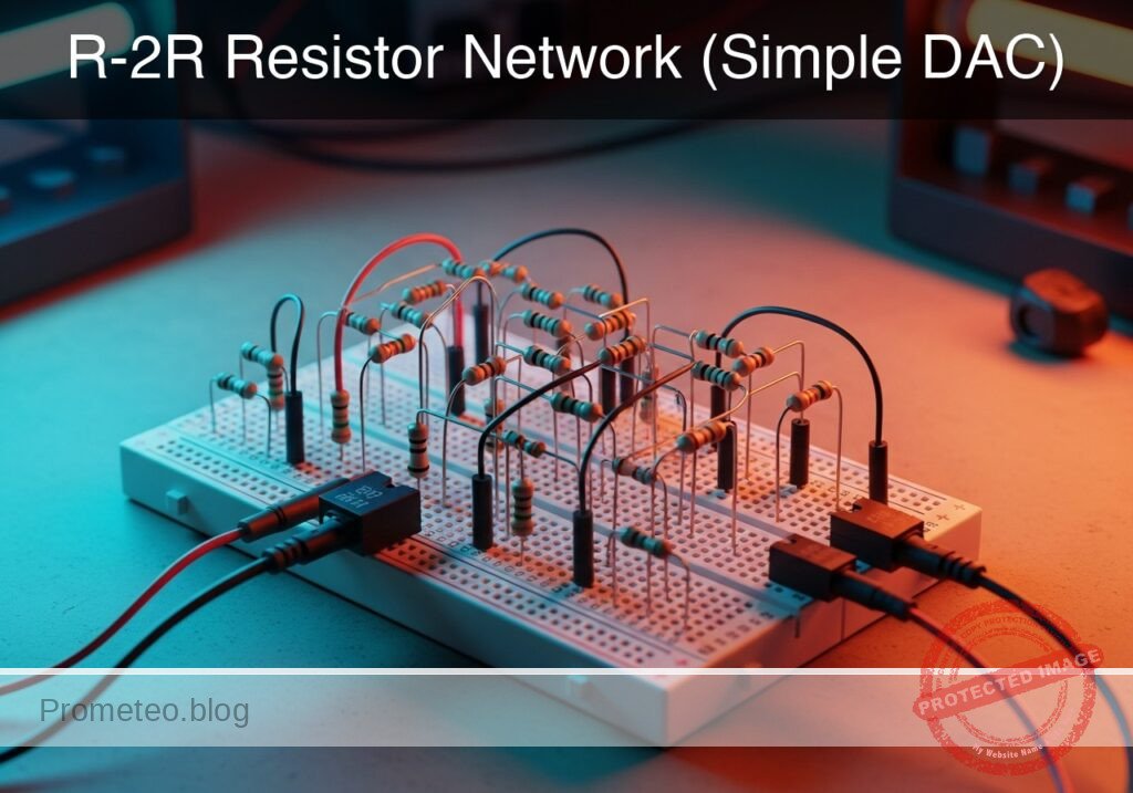
In this session, you will build a 4-bit Digital-to-Analog Converter (DAC) using an R-2R resistor ladder topology. This circuit sums binary weighted inputs to produce an analog output proportional to the digital value.
Why it is useful:
* Audio Synthesis: Used in simple function generators to create sine or triangle waves from digital microcontrollers.
* Video Signals: Historically used in VGA adapters to generate color intensity levels.
* Cost-Effective Control: Allows generating variable control voltages without dedicated DAC chips.
* Signal Processing Education: Demonstrates superposition and Thevenin’s theorem in a practical way.
Expected outcome:
* A stable output voltage (VOUT) that ranges from 0 V to approximately 4.68 V (given a 5 V supply).
* Sixteen distinct voltage steps (from binary 0000 to 1111).
* Linear relationship between the binary input value and the measured analog voltage.
Target audience and level: Electronics students and hobbyists familiar with basic circuit laws.
Materials
- V1: 5 V DC supply, function: Logic high reference and main power.
- R1: 10 kΩ resistor, function: Series resistor (R) in ladder spine (Bit 0-1).
- R2: 10 kΩ resistor, function: Series resistor (R) in ladder spine (Bit 1-2).
- R3: 10 kΩ resistor, function: Series resistor (R) in ladder spine (Bit 2-3).
- R4: 20 kΩ resistor, function: Parallel resistor (2R) for Bit 0 (LSB).
- R5: 20 kΩ resistor, function: Parallel resistor (2R) for Bit 1.
- R6: 20 kΩ resistor, function: Parallel resistor (2R) for Bit 2.
- R7: 20 kΩ resistor, function: Parallel resistor (2R) for Bit 3 (MSB).
- R8: 20 kΩ resistor, function: Termination resistor (2R) connected to Ground.
- SW1: SPDT switch (or jumper wire), function: Bit 0 input (LSB), switches between VCC and GND.
- SW2: SPDT switch (or jumper wire), function: Bit 1 input, switches between VCC and GND.
- SW3: SPDT switch (or jumper wire), function: Bit 2 input, switches between VCC and GND.
- SW4: SPDT switch (or jumper wire), function: Bit 3 input (MSB), switches between VCC and GND.
Wiring guide
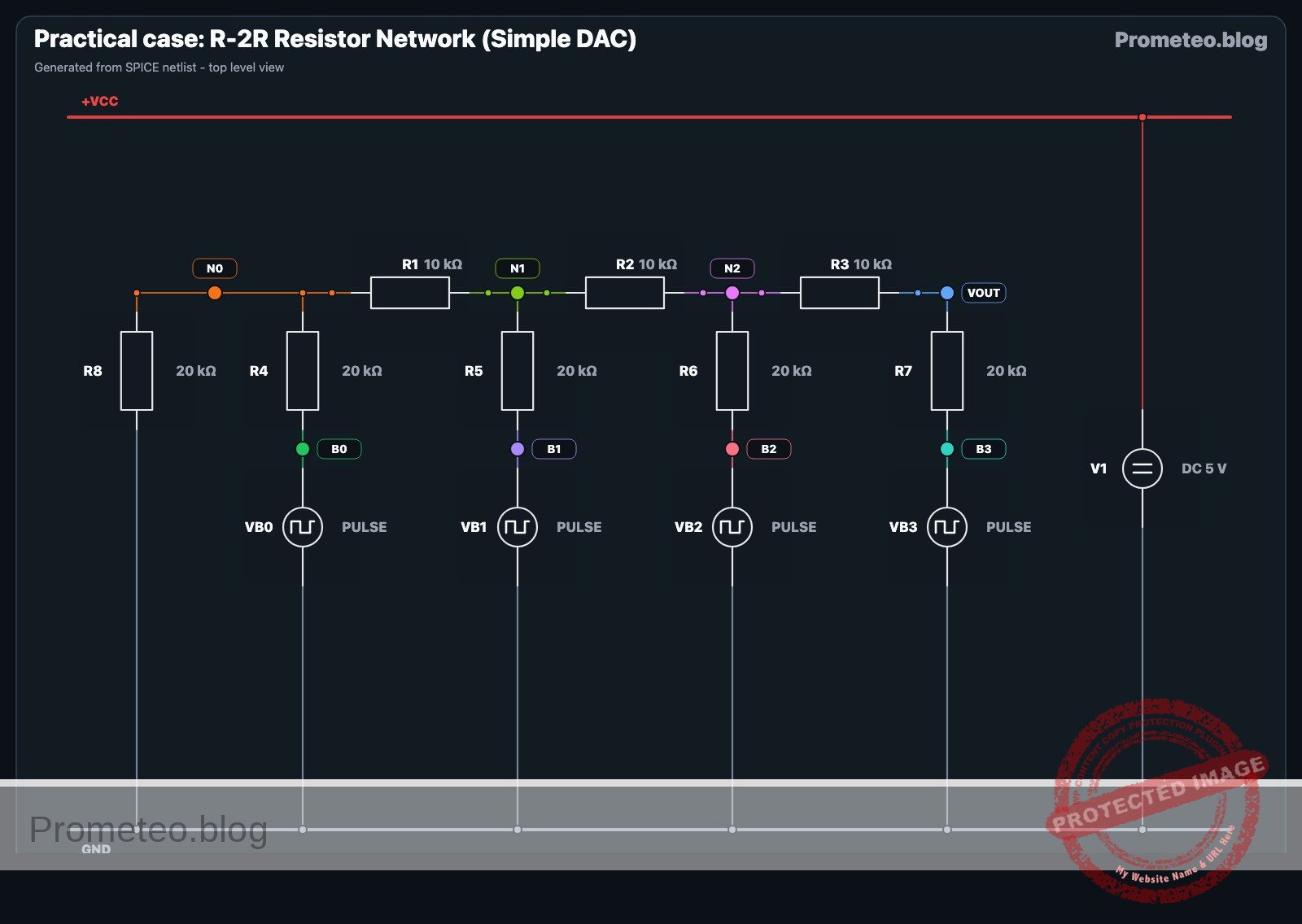
This guide uses node names: VCC (5 V), 0 (GND), B0 (Bit 0 Input), B1 (Bit 1 Input), B2 (Bit 2 Input), B3 (Bit 3 Input), and internal ladder nodes N0, N1, N2. VOUT is the analog output.
- V1 Connection: Connect
V1positive terminal toVCCand negative to0. - Input Switches (Digital Inputs):
- SW1: Common to
B0, Position 1 to0, Position 2 toVCC. - SW2: Common to
B1, Position 1 to0, Position 2 toVCC. - SW3: Common to
B2, Position 1 to0, Position 2 toVCC. - SW4: Common to
B3, Position 1 to0, Position 2 toVCC.
- SW1: Common to
- Ladder «R» Resistors (Spine):
- R1: Connects between node
N0and nodeN1. - R2: Connects between node
N1and nodeN2. - R3: Connects between node
N2and nodeVOUT.
- R1: Connects between node
- Ladder «2R» Resistors (Branches):
- R8 (Termination): Connects between node
N0and0. - R4: Connects between node
B0and nodeN0. - R5: Connects between node
B1and nodeN1. - R6: Connects between node
B2and nodeN2. - R7: Connects between node
B3and nodeVOUT.
- R8 (Termination): Connects between node
- Output: Monitor voltage at node
VOUTrelative to0.
Conceptual block diagram

Schematic
[ DIGITAL INPUTS ]              [ R-2R LADDER NETWORK ]                 [ ANALOG OUTPUT ]
(Switches toggle VCC/GND)           (Voltage Summing Logic)

                                                                           +--> [ Multimeter ]
                                                                           |    (Measure V)
[ SW4: Bit 3 (MSB) ] --(High/Low)--> [ R7: 20k (2R) ] --(Bit 3 Weight)---->+--> [ VOUT Node  ]
                                                            ^
                                                            |
                                                     [ R3: 10k (R) ]
                                                            |
[ SW3: Bit 2       ] --(High/Low)--> [ R6: 20k (2R) ] --(Bit 2 Weight)---->+ (Node N2)
                                                            ^
                                                            |
                                                     [ R2: 10k (R) ]
                                                            |
[ SW2: Bit 1       ] --(High/Low)--> [ R5: 20k (2R) ] --(Bit 1 Weight)---->+ (Node N1)
                                                            ^
                                                            |
                                                     [ R1: 10k (R) ]
                                                            |
[ SW1: Bit 0 (LSB) ] --(High/Low)--> [ R4: 20k (2R) ] --(Bit 0 Weight)---->+ (Node N0)
                                                            |
                                                            v
                                                     [ R8: 20k (2R) ]
                                                            |
                                                           GND
Electrical diagram
Measurements and tests
To validate the DAC, you will set the switches to specific binary codes and measure the resulting voltage at VOUT. The formula for the output is:
$VOUT = Vref × ((Decimal Value) / 16)$
- Zero Check: Set all switches (SW1-SW4) to
0(GND). MeasureVOUT. It should be exactly 0 V. - LSB Check (Bit 0): Set SW1 to
VCCand others to0(Binary 0001).- Calculation: $5 V × (1/16) = 0.3125 V$.
- Verify
VOUTis approx 0.31 V.
- MSB Check (Bit 3): Set SW4 to
VCCand others to0(Binary 1000).- Calculation: $5 V × (8/16) = 2.5 V$.
- Verify
VOUTis approx 2.5 V.
- Full Scale Check: Set all switches to
VCC(Binary 1111).- Calculation: $5 V × (15/16) = 4.6875 V. * Verify
VOUTis approx 4.69 V. <! – – SPICE_INSERT_POINT – – > ## Common mistakes and how to avoid them 1. Floating Inputs: Leaving a switch open (disconnected) instead of connecting it to Ground for logic «0». * Solution: R – 2R ladders require inputs to be strictly atV_{ref}$ or $0 V$. Use SPDT switches or verify your jumper wires connect to GND when «off».
- Calculation: $5 V × (15/16) = 4.6875 V. * Verify
- Swapping R and 2R: Placing a 10 kΩ resistor where a 20 kΩ is required (or vice versa).
- Solution: Double-check color codes. 10 kΩ is usually Brown-Black-Orange; 20 kΩ is Red-Black-Orange.
- Loading the Output: Connecting a low-impedance load (like a speaker or LED) directly to
VOUT.- Solution: This circuit has a relatively high output impedance ($R$). Always use an Op-Amp buffer (voltage follower) if you need to drive a load.
SPICE netlist and simulation
Reference SPICE Netlist (ngspice) — excerptFull SPICE netlist (ngspice)
* Practical case: R-2R Resistor Network (Simple DAC)

* --- Power Supply ---
* V1: 5 V DC supply, function: Logic high reference and main power
V1 VCC 0 DC 5

* --- Digital Inputs (Simulated Switches) ---
* Modeled as PULSE voltage sources to strictly simulate user input/switching.
* Generates a binary counting sequence (0000 to 1111) to test the full truth table.
* Logic High = 5V (VCC), Logic Low = 0V (GND).

* SW1 (Bit 0 LSB): Toggles every 100us (Period)
VB0 B0 0 PULSE(0 5 0 1u 1u 50u 100u)

* SW2 (Bit 1): Toggles every 200us (Period)
VB1 B1 0 PULSE(0 5 0 1u 1u 100u 200u)

* SW3 (Bit 2): Toggles every 400us (Period)
VB2 B2 0 PULSE(0 5 0 1u 1u 200u 400u)

* ... (truncated in public view) ...
Copy this content into a .cir file and run with ngspice.
* Practical case: R-2R Resistor Network (Simple DAC)

* --- Power Supply ---
* V1: 5 V DC supply, function: Logic high reference and main power
V1 VCC 0 DC 5

* --- Digital Inputs (Simulated Switches) ---
* Modeled as PULSE voltage sources to strictly simulate user input/switching.
* Generates a binary counting sequence (0000 to 1111) to test the full truth table.
* Logic High = 5V (VCC), Logic Low = 0V (GND).

* SW1 (Bit 0 LSB): Toggles every 100us (Period)
VB0 B0 0 PULSE(0 5 0 1u 1u 50u 100u)

* SW2 (Bit 1): Toggles every 200us (Period)
VB1 B1 0 PULSE(0 5 0 1u 1u 100u 200u)

* SW3 (Bit 2): Toggles every 400us (Period)
VB2 B2 0 PULSE(0 5 0 1u 1u 200u 400u)

* SW4 (Bit 3 MSB): Toggles every 800us (Period)
VB3 B3 0 PULSE(0 5 0 1u 1u 400u 800u)

* --- R-2R Ladder Network ---

* -- Spine Resistors (R = 10k) --
* R1: Connects between node N0 and node N1
R1 N0 N1 10k

* R2: Connects between node N1 and node N2
R2 N1 N2 10k

* R3: Connects between node N2 and node VOUT
R3 N2 VOUT 10k

* -- Branch/Termination Resistors (2R = 20k) --
* R8 (Termination): Connects between node N0 and 0 (GND)
R8 N0 0 20k

* R4 (Bit 0 Input): Connects between node B0 and node N0
R4 B0 N0 20k

* R5 (Bit 1 Input): Connects between node B1 and node N1
R5 B1 N1 20k

* R6 (Bit 2 Input): Connects between node B2 and node N2
R6 B2 N2 20k

* R7 (Bit 3 Input - MSB): Connects between node B3 and node VOUT
R7 B3 VOUT 20k

* --- Simulation Directives ---
* Transient analysis to capture the full binary counting sequence (approx 1ms)
.tran 2u 1000u

* --- Output Printing ---
* Monitor the Input Bits and the Analog Output Voltage
.print tran V(B0) V(B1) V(B2) V(B3) V(VOUT)

.op
.end
Simulation Results (Transient Analysis)

Show raw data table (1384 rows)
Index   time            v(b0)           v(b1)           v(b2)
0	0.000000e+00	0.000000e+00	0.000000e+00	0.000000e+00
1	1.000000e-08	5.000000e-02	5.000000e-02	5.000000e-02
2	2.000000e-08	1.000000e-01	1.000000e-01	1.000000e-01
3	4.000000e-08	2.000000e-01	2.000000e-01	2.000000e-01
4	8.000000e-08	4.000000e-01	4.000000e-01	4.000000e-01
5	1.600000e-07	8.000000e-01	8.000000e-01	8.000000e-01
6	3.200000e-07	1.600000e+00	1.600000e+00	1.600000e+00
7	6.400000e-07	3.200000e+00	3.200000e+00	3.200000e+00
8	1.000000e-06	5.000000e+00	5.000000e+00	5.000000e+00
9	1.064000e-06	5.000000e+00	5.000000e+00	5.000000e+00
10	1.192000e-06	5.000000e+00	5.000000e+00	5.000000e+00
11	1.448000e-06	5.000000e+00	5.000000e+00	5.000000e+00
12	1.960000e-06	5.000000e+00	5.000000e+00	5.000000e+00
13	2.984000e-06	5.000000e+00	5.000000e+00	5.000000e+00
14	4.984000e-06	5.000000e+00	5.000000e+00	5.000000e+00
15	6.984000e-06	5.000000e+00	5.000000e+00	5.000000e+00
16	8.984000e-06	5.000000e+00	5.000000e+00	5.000000e+00
17	1.098400e-05	5.000000e+00	5.000000e+00	5.000000e+00
18	1.298400e-05	5.000000e+00	5.000000e+00	5.000000e+00
19	1.498400e-05	5.000000e+00	5.000000e+00	5.000000e+00
20	1.698400e-05	5.000000e+00	5.000000e+00	5.000000e+00
21	1.898400e-05	5.000000e+00	5.000000e+00	5.000000e+00
22	2.098400e-05	5.000000e+00	5.000000e+00	5.000000e+00
23	2.298400e-05	5.000000e+00	5.000000e+00	5.000000e+00
... (1360 more rows) ...
Reference SPICE netlist (ngspice)
* Practical case: R-2R Resistor Network (Simple DAC)

* --- Power Supply ---
* V1: 5 V DC supply, function: Logic high reference and main power
V1 VCC 0 DC 5

* --- Digital Inputs (Simulated Switches) ---
* Modeled as PULSE voltage sources to strictly simulate user input/switching.
* Generates a binary counting sequence (0000 to 1111) to test the full truth table.
* Logic High = 5V (VCC), Logic Low = 0V (GND).

* SW1 (Bit 0 LSB): Toggles every 100us (Period)
VB0 B0 0 PULSE(0 5 0 1u 1u 50u 100u)

* SW2 (Bit 1): Toggles every 200us (Period)
VB1 B1 0 PULSE(0 5 0 1u 1u 100u 200u)

* SW3 (Bit 2): Toggles every 400us (Period)
VB2 B2 0 PULSE(0 5 0 1u 1u 200u 400u)

* SW4 (Bit 3 MSB): Toggles every 800us (Period)
VB3 B3 0 PULSE(0 5 0 1u 1u 400u 800u)

* --- R-2R Ladder Network ---

* -- Spine Resistors (R = 10k) --
* R1: Connects between node N0 and node N1
R1 N0 N1 10k

* R2: Connects between node N1 and node N2
R2 N1 N2 10k

* R3: Connects between node N2 and node VOUT
R3 N2 VOUT 10k

* -- Branch/Termination Resistors (2R = 20k) --
* R8 (Termination): Connects between node N0 and 0 (GND)
R8 N0 0 20k

* R4 (Bit 0 Input): Connects between node B0 and node N0
R4 B0 N0 20k

* R5 (Bit 1 Input): Connects between node B1 and node N1
R5 B1 N1 20k

* R6 (Bit 2 Input): Connects between node B2 and node N2
R6 B2 N2 20k

* R7 (Bit 3 Input - MSB): Connects between node B3 and node VOUT
R7 B3 VOUT 20k

* --- Simulation Directives ---
* Transient analysis to capture the full binary counting sequence (approx 1ms)
.tran 2u 1000u

* --- Output Printing ---
* Monitor the Input Bits and the Analog Output Voltage
.print tran V(B0) V(B1) V(B2) V(B3) V(VOUT)

.op
.end
Simulation Results (Transient Analysis)
Troubleshooting
- Symptom: $V_{OUT}$ is 2.5 V when it should be 1.25 V.
- Cause: The MSB (Bit 3) might be stuck high, or resistors are swapped.
- Fix: Check switch continuity and verify resistor placement at node
VOUT.
- Symptom: Output voltages are non-linear or random.
- Cause: Poor connection on the «spine» resistors (R1, R2, R3).
- Fix: Re-seat the resistors on the breadboard to ensure the ladder chain is intact.
- Symptom: Output never reaches near 4.6 V.
- Cause: Resistor tolerance accumulation or low power supply voltage.
- Fix: Measure V1 actual voltage. Use 1% tolerance metal film resistors for better precision.
Possible improvements and extensions
- 8-Bit Expansion: Add four more stages to the ladder (using more R and 2R resistors) to create an 8-bit DAC with 256 voltage steps.
- Active Buffering: Connect
VOUTto an LM358 Op-Amp configured as a unity-gain buffer to drive an LED or a small audio speaker safely.
More Practical Cases on Prometeo.blog
Find this product and/or books on this topic on Amazon
As an Amazon Associate, I earn from qualifying purchases. If you buy through this link, you help keep this project running.
Quick Quiz

Telecommunications Electronics Engineer and Computer Engineer (official degrees in Spain).