Objective and use case
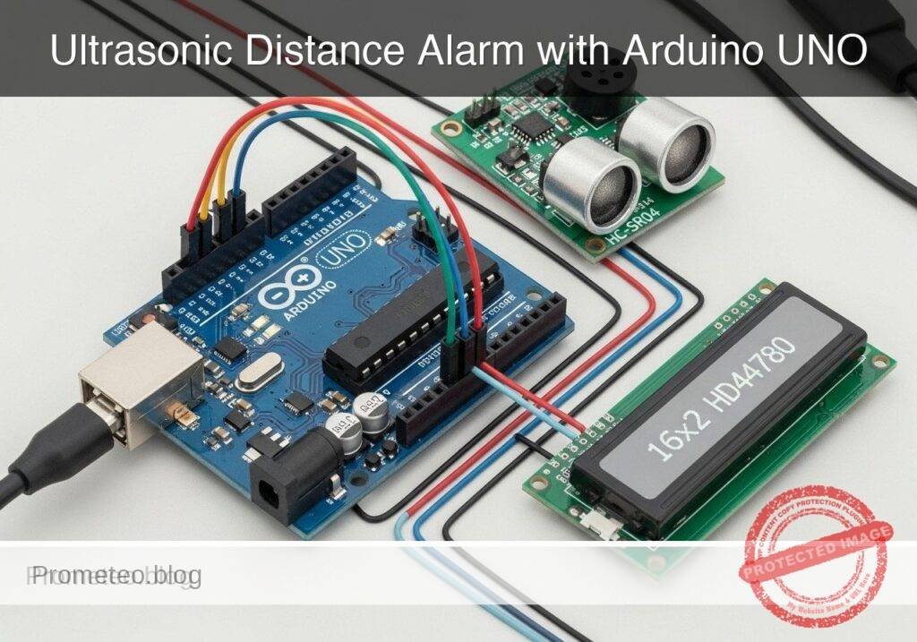
What you’ll build: You will build an educational ultrasonic parking distance alarm prototype that measures vehicle proximity and provides real-time visual and acoustic feedback. The system uses non-blocking logic to simultaneously calculate distance, update an LCD, and modulate a buzzer’s beep frequency based on proximity.
Why it matters / Use cases
- Residential Garage Parking: Helps visualize distance from a wall to prevent bumper damage (e.g., alerting precisely at 30 cm).
- ADAS Foundation: Demonstrates the core principles behind commercial automotive parking sensors.
- Non-blocking Logic: Replaces rudimentary
delay()calls withmillis()-based state machines, allowing concurrent sensor reads and display updates at 10+ Hz without freezing.
Expected outcome
- A functional proximity alarm with < 50ms latency between object detection and buzzer response.
- An LCD interface displaying real-time distance metrics (cm) and dynamic status warnings.
- A passive buzzer that scales its pulse frequency dynamically, culminating in a solid continuous tone at < 10 cm.
Audience: Embedded systems learners and automotive electronics hobbyists; Level: Intermediate
Architecture/flow: Ultrasonic Sensor (Trigger/Echo) → Microcontroller (Non-blocking state machine) → I2C LCD Display & PWM Passive Buzzer
Educational validation note
Before publication, this case passed the Prometeo automated validation gate with status PASS. The validator checked the code blocks, article structure, copy/paste-safe commands and consistency with the supported device catalog.
Published validation evidence
- Automatic result: PASS.
- Parsed structure: 3 sections, 3 tables and 2 code blocks detected before publication.
- Checked code: 1 Arduino/arduino-cli compile, 1 Bash/copy-paste checks.
- Supported catalog: the article text was checked against Prometeo’s validation-capable device profiles, and unsupported stacks block publication.
- Report findings: no blocking findings.
This validation confirms syntax and tool compatibility for the published material, but it does not replace physical testing on your exact hardware, wiring and runtime environment.
Educational safety note
This project is an educational prototype, not a certified product. Before powering the setup, verify the pinout of your exact ULX3S board revision, keep FPGA I/O signals at 3.3 V, never connect 5 V directly to I/O pins, disconnect power before changing wiring, and use suitable external supplies for loads, motors or servos while sharing ground only when the wiring requires it.
Conceptual block diagram
High-level view: what enters the system, what each block processes, and what comes out.
Functional architecture
Conceptual control flow: button input, mode selection, PWM timing and servo motion.

Validation path
The automated validation checks syntax, simulation/lint and compatibility with the ULX3S/ECP5 toolchain.

Prerequisites
To successfully complete this tutorial, you should have:
* A basic understanding of C++ syntax (variables, if/else statements, functions).
* Familiarity with breadboard prototyping and jumper wire connections.
* A computer running Windows, macOS, or Linux with a command-line interface.
* The arduino-cli (Arduino Command Line Interface) installed and added to your system’s PATH.
Materials
You will need the exact components listed below to ensure compatibility with the provided code and wiring instructions:
* Microcontroller: 1x Arduino UNO R3 (ATmega328P).
* Sensor: 1x HC-SR04 ultrasonic sensor.
* Display: 1x 16×2 HD44780 LCD (standard parallel interface, without I2C backpack).
* Audio: 1x Passive buzzer (requires a frequency signal to generate sound).
* Components: 1x 10kΩ potentiometer (for LCD contrast adjustment), 1x 220Ω resistor (for LCD backlight current limiting).
* Prototyping: 1x Standard breadboard and a set of male-to-male jumper wires.
* Power/Data: 1x USB Type-A to Type-B cable.
Setup/Connection
The HD44780 LCD uses a 4-bit parallel interface to save digital pins on the Arduino. The HC-SR04 requires one pin to trigger the ultrasonic pulse and another to read the returning echo.
Power Distribution
- Connect the Arduino 5V pin to the breadboard’s positive power rail.
- Connect the Arduino GND pin to the breadboard’s ground rail.
HC-SR04 Ultrasonic Sensor Connections
| HC-SR04 Pin | Arduino UNO R3 Pin | Description |
|---|---|---|
| VCC | 5V (Power rail) | 5V power supply |
| Trig | Digital Pin 9 | Outputs the 10µs trigger pulse |
| Echo | Digital Pin 10 | Receives the returning pulse width |
| GND | GND (Ground rail) | Ground connection |
Passive Buzzer Connections
| Buzzer Pin | Arduino UNO R3 Pin | Description |
|---|---|---|
| Positive (+) | Digital Pin 8 | PWM/Frequency output via tone() |
| Negative (-) | GND (Ground rail) | Ground connection |
16×2 HD44780 LCD Connections
Note: The 10kΩ potentiometer’s outer legs connect to 5V and GND. The center wiper connects to the LCD’s V0 pin to adjust the text contrast.
| LCD Pin | Name | Arduino / Component Connection | Description |
|---|---|---|---|
| 1 | VSS | GND (Ground rail) | Ground |
| 2 | VDD | 5V (Power rail) | 5V logic power |
| 3 | V0 | Potentiometer center wiper | Contrast adjustment |
| 4 | RS | Digital Pin 12 | Register Select |
| 5 | RW | GND (Ground rail) | Read/Write (tied low for write-only) |
| 6 | E | Digital Pin 11 | Enable pin |
| 11 | D4 | Digital Pin 5 | Data line 4 |
| 12 | D5 | Digital Pin 4 | Data line 5 |
| 13 | D6 | Digital Pin 3 | Data line 6 |
| 14 | D7 | Digital Pin 2 | Data line 7 |
| 15 | A | 5V via 220Ω Resistor | Backlight Anode (+) |
| 16 | K | GND (Ground rail) | Backlight Cathode (-) |
Validated Code
Create a new directory named ParkingAlarm and save the following code as ParkingAlarm.ino. The pin definitions and thresholds are included at the top of the file for easy tuning.
#include <LiquidCrystal.h>

// -----------------------------------------
// Pin Definitions
// -----------------------------------------
#define TRIG_PIN 9
#define ECHO_PIN 10
#define BUZZER_PIN 8

// HD44780 LCD (4-bit mode)
#define LCD_RS 12
#define LCD_EN 11
#define LCD_D4 5
#define LCD_D5 4
#define LCD_D6 3
#define LCD_D7 2

// -----------------------------------------
// System Thresholds (in centimeters)
// -----------------------------------------
#define DIST_MAX   200  // Maximum reliable distance to process
#define DIST_WARN  100  // Start warning (slow beep)
#define DIST_ALARM 50   // Start alarm (dynamic fast beep)
#define DIST_STOP  10   // Stop immediately (continuous tone)

// Initialize the LCD library with the interface pins
LiquidCrystal lcd(LCD_RS, LCD_EN, LCD_D4, LCD_D5, LCD_D6, LCD_D7);

// Variables for non-blocking buzzer timing
unsigned long previousBuzzerMillis = 0;
bool buzzerState = false;

void setup() {
    // Initialize Serial for debugging
    Serial.begin(115200);

    // Configure hardware pins
    pinMode(TRIG_PIN, OUTPUT);
    pinMode(ECHO_PIN, INPUT);
    pinMode(BUZZER_PIN, OUTPUT);

    // Initialize the LCD's columns and rows
    lcd.begin(16, 2);

    // Display a startup message
    lcd.setCursor(0, 0);
    lcd.print("Parking Assist");
    lcd.setCursor(0, 1);
    lcd.print("System Booting..");
    delay(2000); // 2-second boot delay is acceptable here
    lcd.clear();
}

// Function to trigger the HC-SR04 and calculate distance
long readDistance() {
    // Ensure the trigger pin is low before pulsing
    digitalWrite(TRIG_PIN, LOW);
    delayMicroseconds(2);

    // Send a 10 microsecond high pulse to trigger the sensor
    digitalWrite(TRIG_PIN, HIGH);
    delayMicroseconds(10);
    digitalWrite(TRIG_PIN, LOW);

    // Read the echo pin; timeout after 30,000 microseconds (approx 5 meters)
    long duration = pulseIn(ECHO_PIN, HIGH, 30000);

    // If timeout occurred, return -1 to indicate out of range
    if (duration == 0) {
        return -1;
    }

    // Calculate distance in centimeters
    // Speed of sound is 343 m/s or 0.0343 cm/microsecond
    // Divide by 2 to account for the round trip (ping and echo)
    return (duration * 0.0343) / 2;
}

void loop() {
    long distance = readDistance();
    unsigned long currentMillis = millis();

    // Debug output
    Serial.print("Distance: ");
    Serial.println(distance);

    // Top row: Display distance
    lcd.setCursor(0, 0);
    if (distance == -1 || distance > DIST_MAX) {
        lcd.print("Out of Range    "); // Pad with spaces to clear old chars
        noTone(BUZZER_PIN);

        lcd.setCursor(0, 1);
        lcd.print("Status: STANDBY ");
    } else {
        lcd.print("Dist: ");
        if (distance < 100) lcd.print(" "); // Alignment padding
        if (distance < 10)  lcd.print(" "); // Alignment padding
        lcd.print(distance);
        lcd.print(" cm      ");

        // Bottom row: Display status and handle buzzer logic
        lcd.setCursor(0, 1);

        if (distance > DIST_WARN) {
            // Safe zone
            lcd.print("Status: SAFE    ");
            noTone(BUZZER_PIN);

        } else if (distance > DIST_ALARM) {
            // Warning zone: Slow beep
            lcd.print("Status: SLOW    ");
            if (currentMillis - previousBuzzerMillis >= 500) { // 500ms interval
                previousBuzzerMillis = currentMillis;
                buzzerState = !buzzerState;
                if (buzzerState) {
                    tone(BUZZER_PIN, 1000); // 1000 Hz pitch
                } else {
                    noTone(BUZZER_PIN);
                }
            }

        } else if (distance > DIST_STOP) {
            // Alarm zone: Dynamic fast beep
            lcd.print("Status: ALARM   ");

            // Map the distance to a beep interval (closer = faster beep)
            // 50cm -> 400ms interval, 10cm -> 50ms interval
            int beepInterval = map(distance, DIST_STOP, DIST_ALARM, 50, 400);

            if (currentMillis - previousBuzzerMillis >= beepInterval) {
                previousBuzzerMillis = currentMillis;
                buzzerState = !buzzerState;
                if (buzzerState) {
                    tone(BUZZER_PIN, 1500); // 1500 Hz pitch
                } else {
                    noTone(BUZZER_PIN);
                }
            }

        } else {
            // Stop zone: Continuous tone
            lcd.print("Status: STOP!   ");
            tone(BUZZER_PIN, 2000); // 2000 Hz high pitch alert
        }
    }

    // Small delay to stabilize the loop and prevent LCD flickering
    delay(50);
}
Build/Flash/Run commands
We will use the Arduino CLI to compile and upload the code. Open your terminal, navigate to the directory containing the ParkingAlarm folder, and execute the following commands.
Note: Replace /dev/ttyACM0 with your actual serial port (e.g., COM3 on Windows, or /dev/cu.usbmodem14101 on macOS).
# Update the core index
arduino-cli core update-index

# Install the AVR core
arduino-cli core install arduino:avr

# Compile the sketch
arduino-cli compile --fqbn arduino:avr:uno ParkingAlarm

# Upload to the board
arduino-cli upload --fqbn arduino:avr:uno --port /dev/ttyACM0 ParkingAlarm

# Monitor serial output
arduino-cli monitor --port /dev/ttyACM0 --config baudrate=115200
Step-by-step Validation
Follow these checkpoints to ensure your prototype is functioning correctly and meets the performance claims.
- LCD Initialization Check
- Action: Apply power to the Arduino via USB.
- Expected Evidence: The LCD backlight illuminates, and the text “Parking Assist” followed by “System Booting..” appears for 2 seconds before clearing. Adjust the potentiometer if the text is not visible.
- Distance Accuracy Validation
- Action: Place a flat, rigid object (like a piece of cardboard or a book) exactly 50 cm away from the sensor, measured using a physical tape measure.
- Expected Evidence: The LCD should output
Dist: 50 cm(± 1-2 cm tolerance is acceptable due to the speed of sound varying slightly with ambient temperature).
- 10 Hz Update Rate Validation
- Action: Observe the Serial Monitor output timestamps.
- Expected Evidence: The
delay(50)plus the sensor timeout bounds the loop to roughly 100ms per cycle. You should see approximately 10 distance readings printed to the serial console every second, confirming the 10 Hz target rate.
- Acoustic Zone Validation
- Action: Move the rigid object progressively closer to the sensor, starting from 150 cm down to 5 cm.
- Expected Evidence:
- > 100 cm: LCD reads “Status: SAFE”, buzzer is completely silent.
- 99 cm to 51 cm: LCD reads “Status: SLOW”, buzzer emits a steady 1 beep per second.
- 50 cm to 11 cm: LCD reads “Status: ALARM”, buzzer beep rate increases dynamically as the object gets closer.
- <= 10 cm: LCD reads “Status: STOP!”, buzzer emits a continuous, unbroken high-pitched tone.
Find this product and/or books on this topic on Amazon
As an Amazon Associate, I earn from qualifying purchases. If you buy through this link, you help keep this project running.
Quick Quiz

Telecommunications Electronics Engineer and Computer Engineer (official degrees in Spain).