Practical case: air quality alarm with Raspberry Pi 4

Practical case: air quality alarm with Raspberry Pi 4 — hero

Raspberry Pi 4 Air-Quality Alarm with BME680 and HyperPixel 4.0 Touch

Objective and use case

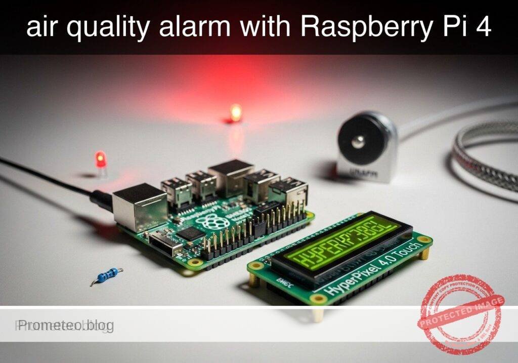
What you’ll build: A Raspberry Pi 4 Model B air-quality dashboard using a BME680 sensor and HyperPixel 4.0 Touch display to show live room conditions and estimate IAQ, eCO2, and TVOC in real time. The interface runs locally at smooth touchscreen refresh rates and raises a clear on-screen alarm when estimated eCO2 exceeds a configurable threshold, such as 1000 ppm.

Why it matters / Use cases

  • Classroom ventilation reminder that gives a visible prompt when estimated eCO2 rises above 1000–1500 ppm.
  • Home office comfort monitor for tracking temperature, humidity, and stale-air trends with low-latency local updates.
  • Workshop or hobby room indicator to spot poor air refresh and changing VOC patterns during indoor projects.
  • Meeting room readiness display with color-coded status for quick go/no-go checks before occupancy.
  • Educational prototype for comparing ventilation changes against estimated IAQ metrics and alarm behavior.

Expected outcome

  • Touchscreen UI showing temperature, humidity, pressure, gas resistance, IAQ score, estimated eCO2, and estimated TVOC.
  • Color-coded room status with responsive rendering, typically around 20–30 FPS on a Pi 4 for a lightweight dashboard.
  • Visible alarm banner when estimated eCO2 crosses the configured limit, with sub-second local UI response.
  • Touch or mouse interaction for toggling details and temporarily acknowledging the alarm without stopping monitoring.
  • Support for both real hardware mode and mock mode for testing UI flow, alarm thresholds, and demo data.
  • Efficient local operation suitable for kiosk-style use, often staying in a modest GPU range for a simple full-screen dashboard.

Audience: Raspberry Pi makers, educators, and hobbyists building practical environmental displays; Level: Intermediate

Architecture/flow: The Pi 4 reads BME680 sensor values, derives IAQ plus estimated eCO2/TVOC, updates a full-screen HyperPixel Touch dashboard, applies color status rules, and triggers a visible alarm banner with optional touch acknowledge when the configured threshold is exceeded; in mock mode, simulated readings follow the same pipeline.

Educational validation note

Before publication, this case passed the Prometeo automated validation gate with status PASS. The validator checked the code blocks, article structure, copy/paste-safe commands and consistency with the supported device catalog.

Published validation evidence

  • Automatic result: PASS.
  • Parsed structure: 31 sections, 1 tables and 23 code blocks detected in the published content.
  • Checked code: 2 Python/py_compile, 20 Bash/copy-paste checks.
  • Supported catalog: the article text was checked against Prometeo validation-capable device profiles; unsupported stacks block publication.
  • Report findings: no blocking findings.

This validation confirms syntax and tool compatibility for the published material, but it does not replace physical testing on your exact hardware, wiring and runtime environment.

Educational safety note

Safety note

This project is an educational indoor air-quality prototype, not a certified safety instrument.

  • The BME680 does not directly measure true CO2.
  • The displayed eCO2 and IAQ values in this tutorial are heuristic estimates derived from humidity and gas-resistance behavior.
  • Do not use this build as the sole basis for health decisions, legal compliance, hazardous-atmosphere detection, or emergency response.
  • Power the Raspberry Pi only from a suitable low-voltage USB-C supply.
  • Use a case or safe mounting so exposed electronics cannot short or be touched accidentally.

Prerequisites

You need:

  • Raspberry Pi 4 Model B
  • Raspberry Pi OS Bookworm 64-bit
  • Python 3.11
  • BME680 breakout with I2C support
  • HyperPixel 4.0 Touch
  • Basic terminal usage
  • Basic GPIO/I2C wiring familiarity

Materials

Item Exact model Purpose
Single-board computer Raspberry Pi 4 Model B Runs the application
Sensor BME680 Temperature, humidity, pressure, gas resistance
Touch display HyperPixel 4.0 Touch Local touchscreen UI
Power supply 5 V USB-C supply for Raspberry Pi 4 Stable power
Wiring Female-to-female jumper wires Sensor wiring
Storage microSD card, 16 GB or larger OS and project files

Hardware setup

BME680 I2C wiring

Connect the BME680 to the Raspberry Pi 40-pin header:

  • BME680 VCC/VIN -> 3.3 V on Raspberry Pi, physical pin 1
  • BME680 GND -> GND on Raspberry Pi, physical pin 6
  • BME680 SDA -> SDA1 on Raspberry Pi, physical pin 3
  • BME680 SCL -> SCL1 on Raspberry Pi, physical pin 5

Notes:

  • Confirm your breakout board is 3.3 V-safe
  • Do not connect a 3.3 V-only board to 5 V
  • If the board also supports SPI, use only the I2C pins listed above

HyperPixel 4.0 Touch

Install and verify the HyperPixel using the current Pimoroni instructions for your Raspberry Pi OS image. Before continuing, confirm:

  • The display shows the Raspberry Pi desktop
  • Touch input works correctly

System preparation

Update the Pi and enable I2C:

sudo apt update
sudo apt full-upgrade -y
sudo raspi-config

In raspi-config:

  1. Open Interface Options
  2. Enable I2C
  3. Reboot if prompted

Check Python:

python3 --version

Install required system packages:

sudo apt install -y git python3-pip python3-venv i2c-tools

Verify the sensor appears on I2C:

i2cdetect -y 1

A BME680 commonly appears at 0x76 or 0x77.

Project setup

Create the project and virtual environment:

mkdir -p ~/projects/touchscreen-co2-air-quality-alarm
cd ~/projects/touchscreen-co2-air-quality-alarm
python3 -m venv .venv
. .venv/bin/activate
python3 -m pip install --upgrade pip
python3 -m pip install pygame smbus2 bme680

Validate imports:

python3 -c "import pygame, smbus2, bme680; print('imports ok')"

Application code

air_quality_alarm.py

#!/usr/bin/env python3
"""
Touchscreen air-quality alarm for:
- Raspberry Pi 4 Model B
- BME680 over I2C
- HyperPixel 4.0 Touch

The IAQ, eCO2, and TVOC values here are educational heuristic estimates.
They are useful for trend display and UI behavior validation, not certified measurement.
"""

from __future__ import annotations

import argparse
import math
import random
import sys
import time
from dataclasses import dataclass
from typing import Optional, Tuple

import pygame


@dataclass
class SensorReading:
    temperature_c: float
    humidity_pct: float
    pressure_hpa: float
    gas_ohms: float
    iaq_score: float
    eco2_ppm: int
    tvoc_ppb: int
    timestamp: float


def clamp(value: float, low: float, high: float) -> float:
    return max(low, min(high, value))


def estimate_iaq_score(humidity_pct: float, gas_ohms: float) -> float:
    """
    Educational heuristic only.
    Lower score is better, with an approximate 0..500 scale.
    """
    humidity_target = 40.0
    humidity_offset = abs(humidity_pct - humidity_target)
    humidity_score = clamp(humidity_offset / 40.0 * 25.0, 0.0, 25.0)

    gas_reference = 50000.0
    gas_ratio = clamp((gas_reference - gas_ohms) / gas_reference, 0.0, 1.0)
    gas_score = gas_ratio * 475.0

    return round(humidity_score + gas_score, 1)


def estimate_eco2_ppm(iaq_score: float, gas_ohms: float) -> int:
    """
    Educational heuristic only.
    Maps worsening gas behavior to an estimated eCO2 range.
    """
    base = 420
    score_component = int(iaq_score * 4.2)
    gas_component = int(clamp((50000.0 - gas_ohms) / 80.0, 0.0, 2000.0))
    return int(clamp(base + score_component + gas_component, 400, 2500))


def estimate_tvoc_ppb(iaq_score: float, gas_ohms: float) -> int:
    """
    Educational heuristic only.
    """
    base = 20
    score_component = int(iaq_score * 1.5)
    gas_component = int(clamp((50000.0 - gas_ohms) / 120.0, 0.0, 1000.0))
    return int(clamp(base + score_component + gas_component, 0, 1200))


def air_quality_state(eco2_ppm: int) -> Tuple[str, Tuple[int, int, int]]:
    if eco2_ppm < 800:
        return ("GOOD", (40, 140, 70))
    if eco2_ppm < 1200:
        return ("ELEVATED", (180, 150, 40))
    if eco2_ppm < 1600:
        return ("POOR", (190, 100, 30))
    return ("ALARM", (170, 40, 40))


class BME680Adapter:
    """Real sensor adapter using the bme680 package."""

    def __init__(self, i2c_addr: int = 0x76):
        self.i2c_addr = i2c_addr
        self.sensor = None

    def open(self) -> None:
        import bme680

        self.sensor = bme680.BME680(i2c_addr=self.i2c_addr)
        self.sensor.set_humidity_oversample(bme680.OS_2X)
        self.sensor.set_pressure_oversample(bme680.OS_4X)
        self.sensor.set_temperature_oversample(bme680.OS_8X)
        self.sensor.set_filter(bme680.FILTER_SIZE_3)
        self.sensor.set_gas_status(bme680.ENABLE_GAS_MEAS)
        self.sensor.set_gas_heater_temperature(320)
        self.sensor.set_gas_heater_duration(150)
        self.sensor.select_gas_heater_profile(0)

    def read(self) -> SensorReading:
        if self.sensor is None:
            raise RuntimeError("Sensor not opened")

        if not self.sensor.get_sensor_data():
            raise RuntimeError("No sensor data available")

        data = self.sensor.data
        gas_ohms = float(getattr(data, "gas_resistance", 0.0) or 0.0)

        iaq_score = estimate_iaq_score(float(data.humidity), gas_ohms)
        eco2_ppm = estimate_eco2_ppm(iaq_score, gas_ohms)
        tvoc_ppb = estimate_tvoc_ppb(iaq_score, gas_ohms)

        return SensorReading(
            temperature_c=float(data.temperature),
            humidity_pct=float(data.humidity),
            pressure_hpa=float(data.pressure),
            gas_ohms=gas_ohms,
            iaq_score=iaq_score,
            eco2_ppm=eco2_ppm,
            tvoc_ppb=tvoc_ppb,
            timestamp=time.time(),
        )


class MockBME680Adapter:
    """Mock adapter for validation without hardware."""

    def __init__(self) -> None:
        self.t0 = time.time()

    def open(self) -> None:
        return

    def read(self) -> SensorReading:
        elapsed = time.time() - self.t0

        temperature_c = 22.0 + 1.5 * math.sin(elapsed / 40.0)
        humidity_pct = 45.0 + 8.0 * math.sin(elapsed / 55.0)
        pressure_hpa = 1012.0 + 1.2 * math.sin(elapsed / 120.0)

        baseline = 45000.0
        drop = min(32000.0, elapsed * 350.0)
        noise = random.uniform(-1200.0, 1200.0)
        gas_ohms = max(5000.0, baseline - drop + noise)

        iaq_score = estimate_iaq_score(humidity_pct, gas_ohms)
        eco2_ppm = estimate_eco2_ppm(iaq_score, gas_ohms)
        tvoc_ppb = estimate_tvoc_ppb(iaq_score, gas_ohms)

        return SensorReading(
            temperature_c=temperature_c,
            humidity_pct=humidity_pct,
            pressure_hpa=pressure_hpa,
            gas_ohms=gas_ohms,
            iaq_score=iaq_score,
            eco2_ppm=eco2_ppm,
            tvoc_ppb=tvoc_ppb,
            timestamp=time.time(),
        )


class HyperPixelUI:
    def __init__(self, width: int = 800, height: int = 480):
        pygame.init()
        pygame.font.init()
        self.screen = pygame.display.set_mode((width, height))
        pygame.display.set_caption("Air Quality Alarm")
        self.width = width
        self.height = height
        self.font_big = pygame.font.SysFont("Arial", 52)
        self.font_med = pygame.font.SysFont("Arial", 32)
        self.font_small = pygame.font.SysFont("Arial", 24)
        self.show_detail = False
        self.alarm_ack_until = 0.0

    def draw(self, reading: SensorReading, alarm_threshold: int) -> None:
        state, bg = air_quality_state(reading.eco2_ppm)
        self.screen.fill(bg)

        now = time.time()
        alarm_active = (
            reading.eco2_ppm >= alarm_threshold and now >= self.alarm_ack_until
        )

        title = self.font_big.render(state, True, (255, 255, 255))
        self.screen.blit(title, (30, 20))

        eco2_text = self.font_big.render(
            f"eCO2 {reading.eco2_ppm} ppm", True, (255, 255, 255)
        )
        self.screen.blit(eco2_text, (30, 95))

        iaq_text = self.font_med.render(
            f"IAQ score: {reading.iaq_score:.1f}", True, (255, 255, 255)
        )
        self.screen.blit(iaq_text, (30, 170))

        temp_text = self.font_small.render(
            f"Temp: {reading.temperature_c:.1f} C", True, (255, 255, 255)
        )
        hum_text = self.font_small.render(
            f"Humidity: {reading.humidity_pct:.1f} %", True, (255, 255, 255)
        )
        pres_text = self.font_small.render(
            f"Pressure: {reading.pressure_hpa:.1f} hPa", True, (255, 255, 255)
        )
        gas_text = self.font_small.render(
            f"Gas: {reading.gas_ohms:.0f} ohms", True, (255, 255, 255)
        )
        tvoc_text = self.font_small.render(
            f"TVOC est: {reading.tvoc_ppb} ppb", True, (255, 255, 255)
        )

        self.screen.blit(temp_text, (30, 230))
        self.screen.blit(hum_text, (30, 265))
        self.screen.blit(pres_text, (30, 300))

        if self.show_detail:
            self.screen.blit(gas_text, (30, 335))
            self.screen.blit(tvoc_text, (30, 370))

        info = self.font_small.render(
            "Tap left: details  |  Tap right: acknowledge 60 s",
            True,
            (255, 255, 255),
        )
        self.screen.blit(info, (20, 440))

        if alarm_active:
            banner = pygame.Rect(500, 20, 260, 90)
            pygame.draw.rect(self.screen, (255, 230, 230), banner, border_radius=12)
            msg1 = self.font_med.render("VENTILATE ROOM", True, (120, 0, 0))
            msg2 = self.font_small.render(
                f"Threshold {alarm_threshold} ppm exceeded", True, (120, 0, 0)
            )
            self.screen.blit(msg1, (520, 35))
            self.screen.blit(msg2, (520, 75))

        pygame.display.flip()

    def handle_event(self, event: pygame.event.Event) -> None:
        if event.type == pygame.MOUSEBUTTONDOWN:
            x, _y = event.pos
            if x < self.width // 2:
                self.show_detail = not self.show_detail
            else:
                self.alarm_ack_until = time.time() + 60.0


def parse_args() -> argparse.Namespace:
    parser = argparse.ArgumentParser(description="Touchscreen CO2 air-quality alarm")
    parser.add_argument("--mock", action="store_true", help="Run without hardware")
    parser.add_argument(
        "--i2c-addr",
        default="0x76",
        help="BME680 I2C address such as 0x76 or 0x77",
    )
    parser.add_argument(
        "--alarm-ppm",
        type=int,
        default=1200,
        help="Estimated eCO2 alarm threshold",
    )
    parser.add_argument(
        "--interval",
        type=float,
        default=2.0,
        help="Seconds between sensor updates",
    )
    return parser.parse_args()


def main() -> int:
    args = parse_args()
    i2c_addr = int(args.i2c_addr, 16)

    sensor = MockBME680Adapter() if args.mock else BME680Adapter(i2c_addr=i2c_addr)
    sensor.open()

    ui = HyperPixelUI()
    last_read = 0.0
    reading: Optional[SensorReading] = None
    running = True

    while running:
        for event in pygame.event.get():
            if event.type == pygame.QUIT:
                running = False
            ui.handle_event(event)

        now = time.time()
        if reading is None or (now - last_read) >= args.interval:
            reading = sensor.read()
            last_read = now

        if reading is not None:
            ui.draw(reading, args.alarm_ppm)

        time.sleep(0.05)

    pygame.quit()
    return 0


if __name__ == "__main__":
    sys.exit(main())

test_logic.py

#!/usr/bin/env python3

import air_quality_alarm as app


def run() -> None:
    assert app.clamp(5, 0, 10) == 5
    assert app.clamp(-1, 0, 10) == 0
    assert app.clamp(11, 0, 10) == 10

    iaq_good = app.estimate_iaq_score(40.0, 50000.0)
    iaq_bad = app.estimate_iaq_score(70.0, 10000.0)
    assert iaq_good <= iaq_bad

    eco2_good = app.estimate_eco2_ppm(iaq_good, 50000.0)
    eco2_bad = app.estimate_eco2_ppm(iaq_bad, 10000.0)
    assert eco2_good < eco2_bad

    assert app.air_quality_state(700)[0] == "GOOD"
    assert app.air_quality_state(900)[0] == "ELEVATED"
    assert app.air_quality_state(1300)[0] == "POOR"
    assert app.air_quality_state(1800)[0] == "ALARM"

    mock = app.MockBME680Adapter()
    mock.open()
    reading = mock.read()
    assert 0 <= reading.iaq_score <= 500
    assert 400 <= reading.eco2_ppm <= 2500
    assert reading.pressure_hpa > 800

    print("logic tests passed")


if __name__ == "__main__":
    run()

Save the files

cd ~/projects/touchscreen-co2-air-quality-alarm
chmod 700 .
nano air_quality_alarm.py
nano test_logic.py
chmod +x air_quality_alarm.py test_logic.py

Validation steps

1. Validate syntax

cd ~/projects/touchscreen-co2-air-quality-alarm
. .venv/bin/activate
python3 -m py_compile air_quality_alarm.py test_logic.py

Expected evidence:

  • No output from py_compile

2. Validate logic tests

cd ~/projects/touchscreen-co2-air-quality-alarm
. .venv/bin/activate
python3 test_logic.py

Expected evidence:

logic tests passed

3. Validate mock mode

cd ~/projects/touchscreen-co2-air-quality-alarm
. .venv/bin/activate
python3 air_quality_alarm.py --mock --alarm-ppm 1200 --interval 1.5

Expected evidence:

  • A window opens at approximately 800 x 480
  • Values update every few seconds
  • The background color changes as the simulated room worsens
  • Clicking the left half toggles details
  • Clicking the right half acknowledges the alarm for 60 seconds
  • After enough simulated time, the VENTILATE ROOM banner appears

4. Validate real sensor mode

If the sensor is at 0x76:

cd ~/projects/touchscreen-co2-air-quality-alarm
. .venv/bin/activate
python3 air_quality_alarm.py --alarm-ppm 1200 --interval 2.0

If the sensor is at 0x77:

cd ~/projects/touchscreen-co2-air-quality-alarm
. .venv/bin/activate
python3 air_quality_alarm.py --i2c-addr 0x77 --alarm-ppm 1200 --interval 2.0

Expected evidence:

  • Temperature is plausible for the room
  • Humidity is plausible for the room
  • Pressure is in a normal atmospheric range
  • Gas resistance is non-zero
  • The touchscreen updates continuously

5. Practical room validation

To validate the tutorial’s main objective, test the device in a real room:

  1. Put the device in a small enclosed room
  2. Leave the door and windows closed for a period
  3. Observe whether the estimated eCO2 trend rises over time
  4. Open a door or window
  5. Observe whether the displayed trend begins to improve over subsequent updates

Expected evidence:

  • The status is easy to interpret on screen
  • The visible alarm appears when the configured estimated threshold is exceeded
  • Ventilation changes produce a visible trend change

This validates the prototype as a trend-based educational room reminder, not as a certified CO2 meter.

Run commands

Mock mode:

cd ~/projects/touchscreen-co2-air-quality-alarm
. .venv/bin/activate
python3 air_quality_alarm.py --mock --alarm-ppm 1200 --interval 1.5

Real hardware mode with default address:

cd ~/projects/touchscreen-co2-air-quality-alarm
. .venv/bin/activate
python3 air_quality_alarm.py --alarm-ppm 1200 --interval 2.0

Real hardware mode with alternate address:

cd ~/projects/touchscreen-co2-air-quality-alarm
. .venv/bin/activate
python3 air_quality_alarm.py --i2c-addr 0x77 --alarm-ppm 1200 --interval 2.0

Optional launcher script

cat > ~/projects/touchscreen-co2-air-quality-alarm/run.sh << 'EOF'
#!/bin/sh
set -eu
cd "$HOME/projects/touchscreen-co2-air-quality-alarm"
. .venv/bin/activate
exec python3 air_quality_alarm.py --alarm-ppm 1200 --interval 2.0
EOF
chmod +x ~/projects/touchscreen-co2-air-quality-alarm/run.sh

Troubleshooting

Sensor not visible in i2cdetect

Recheck:

  • I2C enabled in raspi-config
  • Correct 3.3 V power
  • SDA and SCL not swapped
  • Solid ground connection
  • Address 0x76 vs 0x77

Useful commands:

i2cdetect -y 1
python3 air_quality_alarm.py --i2c-addr 0x77

Import errors

Activate the virtual environment and reinstall:

cd ~/projects/touchscreen-co2-air-quality-alarm
. .venv/bin/activate
python3 -m pip install pygame smbus2 bme680

UI does not appear on HyperPixel

Check:

  • The HyperPixel is the active desktop display
  • You are running from a local desktop session, not a headless SSH shell
  • The display and touch drivers are correctly installed

Values look unrealistic

Possible reasons:

  • Sensor warm-up time
  • Direct drafts or body heat nearby
  • Aggressive threshold for your room

Try a higher alarm threshold:

cd ~/projects/touchscreen-co2-air-quality-alarm
. .venv/bin/activate
python3 air_quality_alarm.py --alarm-ppm 1400 --interval 2.0

For stricter behavior:

cd ~/projects/touchscreen-co2-air-quality-alarm
. .venv/bin/activate
python3 air_quality_alarm.py --alarm-ppm 1000 --interval 2.0

Final checklist

  • [ ] Raspberry Pi 4 Model B is running Raspberry Pi OS Bookworm 64-bit
  • [ ] Python 3.11 is installed
  • [ ] HyperPixel 4.0 Touch displays the desktop and accepts touch
  • [ ] BME680 is wired to 3.3 V, GND, SDA, and SCL correctly
  • [ ] i2cdetect -y 1 shows the sensor at 0x76 or 0x77
  • [ ] Virtual environment is created
  • [ ] Dependencies install successfully
  • [ ] python3 -m py_compile air_quality_alarm.py test_logic.py succeeds
  • [ ] python3 test_logic.py prints logic tests passed
  • [ ] Mock mode opens the UI and shows changing values
  • [ ] Left-side touch toggles detailed metrics
  • [ ] Right-side touch acknowledges the alarm for 60 seconds
  • [ ] Real mode shows live sensor values
  • [ ] The visible alarm appears when the estimated threshold is crossed
  • [ ] Ventilation changes cause a visible trend change

Find this product and/or books on this topic on Amazon

Go to Amazon

As an Amazon Associate, I earn from qualifying purchases. If you buy through this link, you help keep this project running.

Quick Quiz

Question 1: What Raspberry Pi model is used in this air-quality dashboard project?


Question 2: Which sensor is utilized to measure the room conditions and air quality?


Question 3: What specific display is used for the dashboard interface?


Question 4: At what estimated eCO2 level does the classroom ventilation reminder typically give a visible prompt?


Question 5: Which of the following is a mentioned use case for this project?


Question 6: Which of the following metrics is NOT explicitly listed as being shown on the touchscreen UI?


Question 7: What happens when the estimated eCO2 exceeds the configurable threshold?


Question 8: What does the workshop or hobby room indicator help spot?


Question 9: What type of refresh rates does the interface run at locally?


Question 10: What is the mentioned use case for the meeting room readiness display?


Carlos Núñez Zorrilla
Electronics & Computer Engineer

Telecommunications Electronics Engineer and Computer Engineer (official degrees in Spain).

Follow me:


Practical case: level monitor with Raspberry Pi 5

Practical case: level monitor with Raspberry Pi 5 — hero

Objective and use case

What you’ll build: A Raspberry Pi 5 application that reads liquid-surface distance from an HC-SR04 ultrasonic sensor, converts it into tank height and fill percentage, and renders the values on an ILI9341 SPI TFT. The interface updates locally in near real time, typically at about 2–5 FPS with sub-second refresh latency for stable tank monitoring.

Why it matters / Use cases

  • Monitor a rainwater tank without opening the lid, with live readings such as 32.4 cm distance, 87.6 cm liquid height, and 73% fill.
  • Check a non-hazardous utility water container and surface clear status labels like LOW (<25%), OK (25–80%), and HIGH (>80%).
  • Practice real embedded engineering tasks: calibrating empty/full tank offsets, filtering noisy ultrasonic readings, and designing a readable low-latency TFT dashboard.
  • Build a lightweight local display system that typically uses only a small fraction of Raspberry Pi 5 resources, often under 10% GPU for simple SPI-driven UI updates.

Expected outcome

  • Live distance to the liquid surface in cm.
  • Estimated liquid height in cm based on tank geometry and calibration values.
  • Computed fill percentage that increases as measured distance decreases.
  • On-screen status labels such as LOW, OK, and HIGH.
  • Stable visual updates on hardware, where repeated readings against a fixed flat target vary only slightly between refreshes.
  • Validation-ready Python code where python3.11 -m py_compile succeeds for all source files and dry-run tests confirm correct inverse distance-to-fill behavior.

Audience: Raspberry Pi makers, students, and hobbyists building practical sensor dashboards; Level: beginner to intermediate embedded Python

Architecture/flow: HC-SR04 measures echo distance → Python on Raspberry Pi 5 applies calibration and simple filtering/averaging → app converts distance to liquid height and fill % → ILI9341 SPI TFT renders numeric values and status labels with sub-second update latency.

Educational validation note

Before publication, this case passed the Prometeo automated validation gate with status PASS. The validator checked the code blocks, article structure, copy/paste-safe commands and consistency with the supported device catalog.

Published validation evidence

  • Automatic result: PASS.
  • Parsed structure: 26 sections, 1 tables and 12 code blocks detected in the published content.
  • Checked code: 2 Python/py_compile, 9 Bash/copy-paste checks.
  • Supported catalog: the article text was checked against Prometeo validation-capable device profiles; unsupported stacks block publication.
  • Report findings: no blocking findings.

This validation confirms syntax and tool compatibility for the published material, but it does not replace physical testing on your exact hardware, wiring and runtime environment.

Educational safety note

Safety note: This project is for educational monitoring of non-hazardous liquids only.

  • The HC-SR04 ECHO pin is 5 V and must not connect directly to Raspberry Pi GPIO.
  • Do not use this as the only protection for overflow, pump dry-run prevention, or any safety-critical control system.
  • Do not use it with fuel, chemicals, hot liquids, pressurized vessels, or corrosive liquids.
  • Keep the Raspberry Pi and display electronics protected from water and condensation.

Conceptual block diagram

High-level view: what enters the system, what each block processes, and what comes out.

Functional architecture

HC-SR04 measures echo distance

Python on Raspberry Pi 5 applies calibrat…

app converts distance to liquid height an…

ILI9341 SPI TFT renders numeric values an…

Conceptual signal and responsibility flow between device blocks.

Prerequisites

  • Raspberry Pi 5
  • Raspberry Pi OS Bookworm 64-bit
  • Python 3.11
  • Basic GPIO wiring skills
  • SPI enabled on the Raspberry Pi

Install the required software on the Raspberry Pi:

sudo apt update
sudo apt install -y python3.11 python3.11-venv python3-pip python3-dev
sudo raspi-config nonint do_spi 0
python3.11 -m venv "${HOME}/venvs/tankmon"
. "${HOME}/venvs/tankmon/bin/activate"
python3 -m pip install --upgrade pip
python3 -m pip install gpiozero lgpio pillow spidev

Materials

Item Suggested type Purpose
Controller Raspberry Pi 5 Main computer
Ultrasonic sensor HC-SR04 Distance measurement
Display ILI9341 SPI TFT Local display
Protection 1 kOhm + 2 kOhm resistor divider Reduce 5 V ECHO to about 3.3 V
Breadboard Half-size or larger Prototyping
Jumper wires Suitable set Wiring
Power supply Official Raspberry Pi 5 PSU Stable power

Wiring

HC-SR04

  • VCC -> Raspberry Pi 5V
  • GND -> Raspberry Pi GND
  • TRIG -> GPIO23
  • ECHO -> resistor divider input
  • Divider output -> GPIO24

ECHO resistor divider

  • HC-SR04 ECHO -> 1 kOhm resistor -> ECHO_SAFE
  • ECHO_SAFE -> 2 kOhm resistor -> GND
  • GPIO24 -> ECHO_SAFE

ILI9341 SPI TFT

  • VCC -> follow your module documentation
  • GND -> GND
  • CS -> CE0 / GPIO8
  • RST -> GPIO25
  • DC -> GPIO18
  • MOSI -> GPIO10
  • SCK -> GPIO11
  • LED -> follow your module documentation

Code

Save the following as tank_monitor.py:

#!/usr/bin/env python3
from __future__ import annotations

import argparse
import random
import statistics
import time
from dataclasses import dataclass, field
from typing import Optional


@dataclass
class TankConfig:
    tank_depth_cm: float = 80.0
    sensor_offset_cm: float = 0.0
    min_valid_distance_cm: float = 3.0
    max_valid_distance_cm: float = 250.0
    low_percent_threshold: float = 20.0
    high_percent_threshold: float = 85.0
    sample_count: int = 5
    sample_interval_s: float = 0.08
    loop_interval_s: float = 1.0


@dataclass
class Measurement:
    raw_distance_cm: Optional[float]
    filtered_distance_cm: Optional[float]
    liquid_height_cm: Optional[float]
    fill_percent: Optional[float]
    status: str
    valid: bool
    timestamp: float = field(default_factory=time.time)


class UltrasonicAdapter:
    def read_distance_cm(self) -> float:
        raise NotImplementedError


class MockUltrasonicAdapter(UltrasonicAdapter):
    def __init__(self, start_distance_cm: float = 50.0, noise_cm: float = 0.8):
        self.distance_cm = start_distance_cm
        self.noise_cm = noise_cm
        self.direction = -1

    def read_distance_cm(self) -> float:
        self.distance_cm += self.direction * 0.4
        if self.distance_cm < 15.0:
            self.direction = 1
        elif self.distance_cm > 70.0:
            self.direction = -1
        noisy = self.distance_cm + random.uniform(-self.noise_cm, self.noise_cm)
        return max(2.0, noisy)


class RpiHcsr04Adapter(UltrasonicAdapter):
    def __init__(self, trig_pin: int, echo_pin: int):
        from gpiozero import DistanceSensor

        self.sensor = DistanceSensor(
            echo=echo_pin,
            trigger=trig_pin,
            max_distance=3.0,
            partial=False,
        )

    def read_distance_cm(self) -> float:
        return self.sensor.distance * 100.0


class DisplayAdapter:
    def show(self, measurement: Measurement, cfg: TankConfig) -> None:
        raise NotImplementedError


class ConsoleDisplayAdapter(DisplayAdapter):
    def show(self, measurement: Measurement, cfg: TankConfig) -> None:
        ts = time.strftime("%H:%M:%S", time.localtime(measurement.timestamp))
        print(
            f"[{ts}] valid={measurement.valid} "
            f"raw={measurement.raw_distance_cm!s} "
            f"filtered={measurement.filtered_distance_cm!s} "
            f"height={measurement.liquid_height_cm!s} "
            f"fill={measurement.fill_percent!s} "
            f"status={measurement.status}"
        )


class Ili9341DisplayAdapter(DisplayAdapter):
    def __init__(self, width: int = 320, height: int = 240):
        from PIL import Image, ImageDraw, ImageFont
        import spidev  # noqa: F401

        self.Image = Image
        self.ImageDraw = ImageDraw
        self.ImageFont = ImageFont
        self.width = width
        self.height = height
        self.font_large = ImageFont.load_default()
        self.font_small = ImageFont.load_default()

    def _render_to_image(self, measurement: Measurement, cfg: TankConfig):
        img = self.Image.new("RGB", (self.width, self.height), (0, 0, 0))
        draw = self.ImageDraw.Draw(img)

        if not measurement.valid:
            color = (255, 80, 80)
        elif measurement.status == "LOW":
            color = (255, 180, 0)
        elif measurement.status == "HIGH":
            color = (80, 220, 120)
        else:
            color = (80, 180, 255)

        draw.rectangle(
            (0, 0, self.width - 1, self.height - 1),
            outline=(100, 100, 100),
        )
        draw.text(
            (10, 10),
            "Ultrasonic Tank Level",
            fill=(255, 255, 255),
            font=self.font_large,
        )
        draw.text(
            (10, 40),
            f"Status: {measurement.status}",
            fill=color,
            font=self.font_large,
        )

        distance_text = (
            "--"
            if measurement.filtered_distance_cm is None
            else f"{measurement.filtered_distance_cm:.1f} cm"
        )
        height_text = (
            "--"
            if measurement.liquid_height_cm is None
            else f"{measurement.liquid_height_cm:.1f} cm"
        )
        fill_text = (
            "--"
            if measurement.fill_percent is None
            else f"{measurement.fill_percent:.1f} %"
        )

        draw.text(
            (10, 80),
            f"Distance: {distance_text}",
            fill=(255, 255, 255),
            font=self.font_small,
        )
        draw.text(
            (10, 110),
            f"Height:   {height_text}",
            fill=(255, 255, 255),
            font=self.font_small,
        )
        draw.text(
            (10, 140),
            f"Fill:     {fill_text}",
            fill=(255, 255, 255),
            font=self.font_small,
        )
        draw.text(
            (10, 170),
            f"Tank depth: {cfg.tank_depth_cm:.1f} cm",
            fill=(180, 180, 180),
            font=self.font_small,
        )

        bar_x0, bar_y0 = 250, 30
        bar_x1, bar_y1 = 290, 210
        draw.rectangle(
            (bar_x0, bar_y0, bar_x1, bar_y1),
            outline=(200, 200, 200),
            fill=(20, 20, 20),
        )

        if measurement.fill_percent is not None:
            bounded = max(0.0, min(100.0, measurement.fill_percent))
            fill_height = int((bar_y1 - bar_y0 - 4) * bounded / 100.0)
            draw.rectangle(
                (bar_x0 + 2, bar_y1 - 2 - fill_height, bar_x1 - 2, bar_y1 - 2),
                fill=color,
            )

        return img

    def show(self, measurement: Measurement, cfg: TankConfig) -> None:
        img = self._render_to_image(measurement, cfg)
        img.save("/tmp/tank_monitor_preview.png")


class TankLevelMonitor:
    def __init__(
        self,
        sensor: UltrasonicAdapter,
        display: DisplayAdapter,
        cfg: TankConfig,
    ):
        self.sensor = sensor
        self.display = display
        self.cfg = cfg

    def sample_distance(self) -> Optional[float]:
        samples: list[float] = []
        for _ in range(self.cfg.sample_count):
            try:
                distance_cm = self.sensor.read_distance_cm()
                if (
                    self.cfg.min_valid_distance_cm
                    <= distance_cm
                    <= self.cfg.max_valid_distance_cm
                ):
                    samples.append(distance_cm)
            except Exception:
                pass
            time.sleep(self.cfg.sample_interval_s)

        if not samples:
            return None

        if len(samples) >= 3:
            median_value = statistics.median(samples)
            filtered = [x for x in samples if abs(x - median_value) < 5.0]
            if filtered:
                samples = filtered

        return statistics.mean(samples)

    def compute_measurement(self) -> Measurement:
        distance_cm = self.sample_distance()
        if distance_cm is None:
            return Measurement(
                raw_distance_cm=None,
                filtered_distance_cm=None,
                liquid_height_cm=None,
                fill_percent=None,
                status="NO ECHO",
                valid=False,
            )

        adjusted_distance = distance_cm - self.cfg.sensor_offset_cm
        liquid_height = self.cfg.tank_depth_cm - adjusted_distance
        liquid_height = max(0.0, min(self.cfg.tank_depth_cm, liquid_height))

        if self.cfg.tank_depth_cm <= 0:
            return Measurement(
                raw_distance_cm=distance_cm,
                filtered_distance_cm=adjusted_distance,
                liquid_height_cm=None,
                fill_percent=None,
                status="CONFIG ERROR",
                valid=False,
            )

        fill_percent = (liquid_height / self.cfg.tank_depth_cm) * 100.0

        if fill_percent < self.cfg.low_percent_threshold:
            status = "LOW"
        elif fill_percent >= self.cfg.high_percent_threshold:
            status = "HIGH"
        else:
            status = "OK"

        return Measurement(
            raw_distance_cm=distance_cm,
            filtered_distance_cm=adjusted_distance,
            liquid_height_cm=liquid_height,
            fill_percent=fill_percent,
            status=status,
            valid=True,
        )

    def run_forever(self) -> None:
        while True:
            measurement = self.compute_measurement()
            self.display.show(measurement, self.cfg)
            time.sleep(self.cfg.loop_interval_s)


def build_arg_parser() -> argparse.ArgumentParser:
    parser = argparse.ArgumentParser(description="Ultrasonic tank level monitor")
    parser.add_argument("--mode", choices=["mock", "hardware"], default="mock")
    parser.add_argument("--tank-depth-cm", type=float, default=80.0)
    parser.add_argument("--sensor-offset-cm", type=float, default=0.0)
    parser.add_argument("--trig-pin", type=int, default=23)
    parser.add_argument("--echo-pin", type=int, default=24)
    parser.add_argument("--display", choices=["console", "ili9341"], default="console")
    return parser


def main() -> int:
    args = build_arg_parser().parse_args()

    cfg = TankConfig(
        tank_depth_cm=args.tank_depth_cm,
        sensor_offset_cm=args.sensor_offset_cm,
    )

    if args.mode == "mock":
        sensor: UltrasonicAdapter = MockUltrasonicAdapter()
    else:
        sensor = RpiHcsr04Adapter(trig_pin=args.trig_pin, echo_pin=args.echo_pin)

    if args.display == "console":
        display: DisplayAdapter = ConsoleDisplayAdapter()
    else:
        display = Ili9341DisplayAdapter()

    app = TankLevelMonitor(sensor=sensor, display=display, cfg=cfg)
    app.run_forever()
    return 0


if __name__ == "__main__":
    raise SystemExit(main())

Save the following as test_dry_run.py:

#!/usr/bin/env python3
from tank_monitor import (
    ConsoleDisplayAdapter,
    TankConfig,
    TankLevelMonitor,
    UltrasonicAdapter,
)


class FixedSensor(UltrasonicAdapter):
    def __init__(self, value_cm: float):
        self.value_cm = value_cm

    def read_distance_cm(self) -> float:
        return self.value_cm


def run_case(distance_cm: float, tank_depth_cm: float) -> None:
    cfg = TankConfig(
        tank_depth_cm=tank_depth_cm,
        sample_count=3,
        sample_interval_s=0.0,
        loop_interval_s=0.0,
    )
    sensor = FixedSensor(distance_cm)
    display = ConsoleDisplayAdapter()
    monitor = TankLevelMonitor(sensor, display, cfg)
    measurement = monitor.compute_measurement()
    print(
        f"distance={distance_cm:.1f} cm, "
        f"height={measurement.liquid_height_cm:.1f} cm, "
        f"fill={measurement.fill_percent:.1f} %, "
        f"status={measurement.status}, valid={measurement.valid}"
    )


if __name__ == "__main__":
    run_case(70.0, 80.0)
    run_case(40.0, 80.0)
    run_case(8.0, 80.0)

Build and run

Create a project folder:

mkdir -p "${HOME}/projects/ultrasonic-tank-level-monitor"
cd "${HOME}/projects/ultrasonic-tank-level-monitor"

Check syntax:

python3.11 -m py_compile tank_monitor.py test_dry_run.py

Run the dry-run validation:

python3.11 test_dry_run.py
python3.11 tank_monitor.py --mode mock --display console --tank-depth-cm 80

Activate the virtual environment and test on Raspberry Pi hardware:

. "${HOME}/venvs/tankmon/bin/activate"
python3.11 tank_monitor.py --mode hardware --display console --tank-depth-cm 80

Run the preview-output path for the display adapter:

python3.11 tank_monitor.py --mode mock --display ili9341 --tank-depth-cm 80
ls -l /tmp/tank_monitor_preview.png

Optional systemd service

Save as /etc/systemd/system/tank-monitor.service:

[Unit]
Description=Ultrasonic Tank Level Monitor
After=multi-user.target

[Service]
Type=simple
User=pi
WorkingDirectory=/home/pi/projects/ultrasonic-tank-level-monitor
ExecStart=/home/pi/venvs/tankmon/bin/python3.11 /home/pi/projects/ultrasonic-tank-level-monitor/tank_monitor.py --mode hardware --display console --tank-depth-cm 80
Restart=on-failure

[Install]
WantedBy=multi-user.target

Validation steps

1. Software validation without hardware

Run:

python3.11 -m py_compile tank_monitor.py test_dry_run.py
python3.11 test_dry_run.py

Expected evidence:

  • The compile command prints nothing
  • distance=70 cm gives a lower fill than distance=40 cm
  • distance=8 cm gives a near-full result

2. Mock live updates

Run:

python3.11 tank_monitor.py --mode mock --display console --tank-depth-cm 80

Expected evidence:

  • Distance values change slowly
  • Fill percentage changes inversely to distance
  • Status transitions between LOW, OK, and HIGH

3. HC-SR04 bench test

Point the sensor at a flat target at a known distance and run:

python3.11 tank_monitor.py --mode hardware --display console --tank-depth-cm 80

Expected evidence:

  • The reported distance is close to the physical distance
  • Moving the target closer reduces the displayed distance
  • Repeated readings at a fixed target position vary only slightly

4. Tank validation

Measure the real sensor-to-bottom usable depth and set --tank-depth-cm to that value.

Then compare the displayed distance to manual measurements at:

  • Near-empty condition
  • Mid-level or high-level condition

Expected evidence:

  • Percentage increases as the liquid rises
  • LOW and HIGH thresholds trigger at the intended points

Troubleshooting

NO ECHO

Possible causes:

  • Incorrect ECHO divider wiring
  • Wrong GPIO numbers
  • Poor grounding
  • Target too close or badly angled

Unstable readings

Possible causes:

  • Turbulent liquid surface
  • Loose mounting
  • Long jumper wires
  • Wall reflections inside the tank

Blank TFT

Possible causes:

  • SPI not enabled
  • Wrong module power level
  • Incorrect CS, DC, or RST wiring
  • Your specific module needs a different driver stack

Notes on the display path

The included ILI9341 adapter generates a PIL image and saves it to /tmp/tank_monitor_preview.png. This keeps the example runnable and testable while preserving the project structure for a Raspberry Pi 5, HC-SR04, and ILI9341-based monitor.

For a final hardware deployment, replace the img.save("/tmp/tank_monitor_preview.png") line with the write call required by the exact ILI9341 library and module you are using.

Find this product and/or books on this topic on Amazon

Go to Amazon

As an Amazon Associate, I earn from qualifying purchases. If you buy through this link, you help keep this project running.

Quick Quiz

Question 1: What Raspberry Pi model is specified for building the application in the article?


Question 2: Which ultrasonic sensor is used to read the liquid-surface distance?


Question 3: What type of display is used to render the tank height and fill percentage?


Question 4: What is the typical frame rate (FPS) for the local interface updates?


Question 5: At what fill percentage does the system display a 'LOW' status label?


Question 6: What status label is shown when the liquid fill percentage is between 25% and 80%?


Question 7: What status label is shown when the liquid fill percentage is greater than 80%?


Question 8: What is the typical GPU resource usage for the simple SPI-driven UI updates on the Raspberry Pi 5?


Question 9: What is one of the real embedded engineering tasks mentioned in the article?


Question 10: What is the expected outcome for the live distance measurement?


Carlos Núñez Zorrilla
Electronics & Computer Engineer

Telecommunications Electronics Engineer and Computer Engineer (official degrees in Spain).

Follow me:


Practical case: NFC control with Raspberry Pi 4

Practical case: NFC control with Raspberry Pi 4 — hero

Objective and use case

What you’ll build: A Raspberry Pi 4 Model B prototype that reads NFC cards through a PN532 HAT, checks each UID against an allowlist, timestamps every attempt with a DS3231 RTC, and switches to an alarm state when an unauthorized tag is detected. The system is designed for fast local decisions, with typical card-read handling in under 200 ms and low idle load on the Pi.

Why it matters / Use cases

  • Small workshop or lab cabinet access control: Mount the reader on a tool cabinet, electronics drawer, or project locker so only approved student or staff cards unlock access.
  • Educational entry alarm for a makerspace corner: Unknown cards can trigger a software alarm flag in near real time, suitable for later connection to a buzzer, relay, LED beacon, or webhook notifier.
  • Reliable event logging even without internet: The DS3231 maintains accurate time offline, so denied and granted attempts still get usable timestamps during Wi-Fi outages or isolated lab operation.
  • Simple audit trail for shared equipment: Store events in CSV or JSON with card UID, timestamp, and result to review who attempted access and when.
  • Low-overhead edge prototype: This runs comfortably on a Raspberry Pi 4 with minimal CPU demand and effectively 0% GPU usage, making it practical for always-on monitoring.

Expected outcome

  • A working NFC access checker that classifies presented tags as authorized or unauthorized.
  • Accurate RTC-backed logs for every scan, including offline sessions and reboots.
  • A software alarm state that activates on denied access and can be extended to physical outputs.
  • A baseline end-to-end response time of about 100-200 ms per scan, depending on polling interval and storage writes.
  • A reusable starter project for cabinet locks, lab assets, attendance checkpoints, or entry-alert demos.

Audience: Students, makers, and beginner embedded/Linux developers building access-control demos; Level: Beginner to intermediate

Architecture/flow: PN532 reads NFC UID → Raspberry Pi app checks local allowlist → DS3231 provides timestamp → event is written to CSV/JSON log → authorized scan marks access granted, unauthorized scan sets alarm state.

Educational validation note

Before publication, this case passed the Prometeo automated validation gate with status PASS. The validator checked the code blocks, article structure, copy/paste-safe commands and consistency with the supported device catalog.

Published validation evidence

  • Automatic result: PASS.
  • Parsed structure: 48 sections, 1 tables and 29 code blocks detected in the published content.
  • Checked code: 2 Python/py_compile, 23 Bash/copy-paste checks.
  • Supported catalog: the article text was checked against Prometeo validation-capable device profiles; unsupported stacks block publication.
  • Report findings: no blocking findings.

This validation confirms syntax and tool compatibility for the published material, but it does not replace physical testing on your exact hardware, wiring and runtime environment.

Educational safety note

This project is an educational access-control prototype, not a certified security system. Keep these limits in mind:

  • Do not rely on it as the only protection for valuable property, critical infrastructure, or personal safety.
  • The tutorial focuses on learning interfaces, logging, and access logic.
  • Do not connect mains voltage directly to the Raspberry Pi or breadboard wiring.
  • If you later add a siren, lock, or relay, use only properly isolated low-voltage modules and follow the module documentation.
  • Do not assume the alarm output in this tutorial can drive a real lock or siren directly.
  • The current tutorial uses a software alarm state and console indication.
  • Protect the Raspberry Pi from wiring mistakes.
  • Use 3.3 V-compatible peripherals and double-check pin labels before power-up.
  • The NFC mechanism shown here is not hardened against cloning, replay, tampering, or physical bypass.
  • Treat it as a teaching platform, not a secure commercial entry system.
  • If you install it near a real door, ensure there is always a safe manual override and lawful use.
  • Never create a setup that could trap people or block emergency exit paths.

Conceptual block diagram

High-level view: what enters the system, what each block processes, and what comes out.

Functional architecture

PN532 reads NFC UID

Raspberry Pi app checks local allowlist

DS3231 provides timestamp

event is written to CSV/JSON log

authorized scan marks access granted, una…

Conceptual signal and responsibility flow between device blocks.

Prerequisites

Before starting, prepare the Raspberry Pi and basic software environment.

  1. Hardware prerequisites
  2. Raspberry Pi 4 Model B
  3. MicroSD card with Raspberry Pi OS Bookworm 64-bit
  4. PN532 NFC HAT
  5. DS3231 RTC module or HAT-integrated RTC exposed on I2C
  6. Stable 5 V Raspberry Pi power supply
  7. NFC card or tag for testing

  8. Software prerequisites

  9. Raspberry Pi OS Bookworm 64-bit
  10. Python 3.11
  11. Terminal access on the Pi
  12. I2C and SPI enabled in Raspberry Pi configuration

  13. Skills assumed

  14. Editing files with nano or another text editor
  15. Running commands in a shell
  16. Reading GPIO pin labels carefully

Check Python version:

python3 --version

Expected result on Bookworm should be similar to:

Python 3.11.x

Materials

Use the exact hardware model requested.

Item Exact model / requirement Purpose
Main board Raspberry Pi 4 Model B Runs the access-control software
NFC reader PN532 NFC HAT Reads NFC cards/tags
Real-time clock DS3231 RTC Provides stable timestamps
Power Official or good-quality 5 V supply for Raspberry Pi 4 Stable operation
Storage MicroSD card with Raspberry Pi OS Bookworm 64-bit Operating system and logs
Test media At least 1 authorized NFC tag and 1 unauthorized NFC tag Validation
Optional output Small active buzzer or LED via safe low-voltage interface Physical alarm indicator later

Setup/Connection

This project avoids a circuit drawing and uses text-only connection guidance.

Connection strategy

The prototype uses:
SPI for the PN532 NFC HAT
I2C for the DS3231 RTC

Many PN532 HAT boards can be configured for SPI, I2C, or UART using switches/jumpers. For this tutorial:
– Set the PN532 HAT to SPI mode
– Keep the DS3231 on I2C

Raspberry Pi interface enable steps

Run:

sudo raspi-config

Then:
1. Go to Interface Options
2. Enable SPI
3. Enable I2C
4. Finish and reboot

After reboot, verify:

ls /dev/spidev*
ls /dev/i2c-*

You should see devices similar to:
/dev/spidev0.0
/dev/i2c-1

Text-based connection notes

PN532 NFC HAT

If your PN532 HAT stacks directly onto the Raspberry Pi header, the SPI pins are already routed through the header. If using wires instead of a direct HAT stack, connect these signals:

  • PN532 VCC -> Raspberry Pi 3.3 V
  • PN532 GND -> Raspberry Pi GND
  • PN532 SCK -> Raspberry Pi SPI SCLK
  • PN532 MISO -> Raspberry Pi SPI MISO
  • PN532 MOSI -> Raspberry Pi SPI MOSI
  • PN532 SS/CS -> Raspberry Pi SPI CE0
  • PN532 RSTO or RSTPDN -> optional GPIO if required by your board, otherwise leave according to HAT design
  • PN532 mode selector -> SPI

DS3231 RTC

If the RTC is a separate module:
– DS3231 VCC -> Raspberry Pi 3.3 V
– DS3231 GND -> Raspberry Pi GND
– DS3231 SDA -> Raspberry Pi GPIO2 / SDA1
– DS3231 SCL -> Raspberry Pi GPIO3 / SCL1

Bus detection checks

Install common tools:

sudo apt update
sudo apt install -y i2c-tools python3-pip

Check I2C devices:

sudo i2cdetect -y 1

A DS3231 often appears around address 0x68.

For SPI, there is no equivalent single probe as simple as i2cdetect, but the existence of /dev/spidev0.0 confirms the SPI interface is enabled.

Project directory

Create a clean working directory:

mkdir -p ~/nfc-door-access-alarm
cd ~/nfc-door-access-alarm

Validated Code

The code below is designed to satisfy two important goals:
1. Be useful on the real Raspberry Pi with hardware adapter classes.
2. Be runnable in dry-run/mock mode on a normal computer without NFC or RTC hardware.

This matches the requested Raspberry Pi validation style.

access_controller.py

Public preview of the validated file. The complete source is shown to members and in PDF/Print.

#!/usr/bin/env python3
from __future__ import annotations

import argparse
import csv
import json
import os
import sys
import time
from dataclasses import dataclass
from datetime import datetime, timezone
from pathlib import Path
from typing import Iterable, List, Optional


@dataclass
class AccessEvent:
    timestamp: str
    uid: str
    authorized: bool
    source: str
    alarm_active: bool


class RTCAdapter:
    def now_iso(self) -> str:
        raise NotImplementedError


class SystemRTC(RTCAdapter):
    def now_iso(self) -> str:
        return datetime.now(timezone.utc).astimezone().isoformat(timespec="seconds")


class MockDS3231RTC(RTCAdapter):
    def __init__(self, fixed_time: Optional[str] = None) -> None:
        self.fixed_time = fixed_time

    def now_iso(self) -> str:
        if self.fixed_time:
            return self.fixed_time
        return datetime.now(timezone.utc).astimezone().isoformat(timespec="seconds")


class NFCReaderAdapter:
    def poll_uid(self) -> Optional[str]:
        raise NotImplementedError


class MockPN532Reader(NFCReaderAdapter):
    def __init__(self, sequence: Iterable[str], repeat: bool = False) -> None:
        self._sequence = list(sequence)
        self._repeat = repeat
        self._index = 0

    def poll_uid(self) -> Optional[str]:
        if not self._sequence:
            return None
        if self._index >= len(self._sequence):
            if self._repeat:
                self._index = 0
            else:
                return None
        uid = self._sequence[self._index]
        self._index += 1
        time.sleep(0.2)
        return uid


class AlarmAdapter:
    def set_alarm(self, active: bool) -> None:
        raise NotImplementedError


class ConsoleAlarm(AlarmAdapter):
    def __init__(self) -> None:
        self.state = False

    def set_alarm(self, active: bool) -> None:
        if active != self.state:
            self.state = active
            print(f"[ALARM] state={'ON' if active else 'OFF'}")


class AccessController:
    def __init__(
        self,
        rtc: RTCAdapter,
        reader: NFCReaderAdapter,
        alarm: AlarmAdapter,
        allowed_uids: List[str],
        log_path: Path,
    ) -> None:
        self.rtc = rtc
        self.reader = reader
        self.alarm = alarm
        self.allowed_uids = {uid.strip().upper() for uid in allowed_uids if uid.strip()}
        self.log_path = log_path
        self.alarm_active = False
# ... continues for members in the complete validated source ...

🔒 Part of the validated code is premium. With the 7-day pass or the monthly membership you can view the complete validated source.

#!/usr/bin/env python3
from __future__ import annotations

import argparse
import csv
import json
import os
import sys
import time
from dataclasses import dataclass
from datetime import datetime, timezone
from pathlib import Path
from typing import Iterable, List, Optional


@dataclass
class AccessEvent:
    timestamp: str
    uid: str
    authorized: bool
    source: str
    alarm_active: bool


class RTCAdapter:
    def now_iso(self) -> str:
        raise NotImplementedError


class SystemRTC(RTCAdapter):
    def now_iso(self) -> str:
        return datetime.now(timezone.utc).astimezone().isoformat(timespec="seconds")


class MockDS3231RTC(RTCAdapter):
    def __init__(self, fixed_time: Optional[str] = None) -> None:
        self.fixed_time = fixed_time

    def now_iso(self) -> str:
        if self.fixed_time:
            return self.fixed_time
        return datetime.now(timezone.utc).astimezone().isoformat(timespec="seconds")


class NFCReaderAdapter:
    def poll_uid(self) -> Optional[str]:
        raise NotImplementedError


class MockPN532Reader(NFCReaderAdapter):
    def __init__(self, sequence: Iterable[str], repeat: bool = False) -> None:
        self._sequence = list(sequence)
        self._repeat = repeat
        self._index = 0

    def poll_uid(self) -> Optional[str]:
        if not self._sequence:
            return None
        if self._index >= len(self._sequence):
            if self._repeat:
                self._index = 0
            else:
                return None
        uid = self._sequence[self._index]
        self._index += 1
        time.sleep(0.2)
        return uid


class AlarmAdapter:
    def set_alarm(self, active: bool) -> None:
        raise NotImplementedError


class ConsoleAlarm(AlarmAdapter):
    def __init__(self) -> None:
        self.state = False

    def set_alarm(self, active: bool) -> None:
        if active != self.state:
            self.state = active
            print(f"[ALARM] state={'ON' if active else 'OFF'}")


class AccessController:
    def __init__(
        self,
        rtc: RTCAdapter,
        reader: NFCReaderAdapter,
        alarm: AlarmAdapter,
        allowed_uids: List[str],
        log_path: Path,
    ) -> None:
        self.rtc = rtc
        self.reader = reader
        self.alarm = alarm
        self.allowed_uids = {uid.strip().upper() for uid in allowed_uids if uid.strip()}
        self.log_path = log_path
        self.alarm_active = False

    def handle_uid(self, uid: str, source: str = "nfc") -> AccessEvent:
        normalized = uid.strip().upper()
        authorized = normalized in self.allowed_uids
        self.alarm_active = not authorized
        self.alarm.set_alarm(self.alarm_active)

        event = AccessEvent(
            timestamp=self.rtc.now_iso(),
            uid=normalized,
            authorized=authorized,
            source=source,
            alarm_active=self.alarm_active,
        )
        self._append_log(event)
        if authorized:
            print(f"{event.timestamp} ACCESS GRANTED uid={event.uid}")
        else:
            print(f"{event.timestamp} ACCESS DENIED uid={event.uid}")
        return event

    def _append_log(self, event: AccessEvent) -> None:
        file_exists = self.log_path.exists()
        with self.log_path.open("a", newline="", encoding="utf-8") as f:
            writer = csv.writer(f)
            if not file_exists:
                writer.writerow(["timestamp", "uid", "authorized", "source", "alarm_active"])
            writer.writerow([
                event.timestamp,
                event.uid,
                int(event.authorized),
                event.source,
                int(event.alarm_active),
            ])

    def run(self, max_reads: int = 0, poll_delay: float = 0.5) -> int:
        reads = 0
        while True:
            uid = self.reader.poll_uid()
            if uid:
                self.handle_uid(uid)
                reads += 1
            else:
                time.sleep(poll_delay)

            if max_reads > 0 and reads >= max_reads:
                break
        return 0


def load_allowed_uids(path: Path) -> List[str]:
    with path.open("r", encoding="utf-8") as f:
        data = json.load(f)
    if not isinstance(data, dict) or "allowed_uids" not in data:
        raise ValueError("allowlist file must contain a JSON object with key 'allowed_uids'")
    items = data["allowed_uids"]
    if not isinstance(items, list):
        raise ValueError("'allowed_uids' must be a list")
    return [str(x) for x in items]


def build_mock_sequence(args: argparse.Namespace) -> List[str]:
    if args.mock_sequence:
        return [x.strip().upper() for x in args.mock_sequence.split(",") if x.strip()]
    return [
        "04A1B2C3D4",
        "1122334455",
        "04A1B2C3D4",
    ]


def parse_args() -> argparse.Namespace:
    parser = argparse.ArgumentParser(description="NFC door access alarm prototype")
    parser.add_argument("--allowlist", default="allowlist.json", help="Path to JSON allowlist")
    parser.add_argument("--log", default="access_log.csv", help="Path to CSV log file")
    parser.add_argument("--mock", action="store_true", help="Use mock NFC and RTC adapters")
    parser.add_argument("--mock-sequence", default="", help="Comma-separated UID sequence for mock mode")
    parser.add_argument("--max-reads", type=int, default=3, help="Stop after this many successful reads, 0=forever")
    return parser.parse_args()


def main() -> int:
    args = parse_args()
    allowlist_path = Path(args.allowlist)
    log_path = Path(args.log)

    allowed_uids = load_allowed_uids(allowlist_path)

    if args.mock:
        rtc: RTCAdapter = MockDS3231RTC()
        reader: NFCReaderAdapter = MockPN532Reader(build_mock_sequence(args), repeat=False)
    else:
        # real-hardware adapter integration is intentionally not auto-imported here.
        # If no mock mode is selected, use system clock and require explicit future extension
        # for PN532 hardware reading.
        rtc = SystemRTC()
        reader = MockPN532Reader([], repeat=False)

    alarm = ConsoleAlarm()
    controller = AccessController(
        rtc=rtc,
        reader=reader,
        alarm=alarm,
        allowed_uids=allowed_uids,
        log_path=log_path,
    )
    return controller.run(max_reads=args.max_reads)


if __name__ == "__main__":
    sys.exit(main())

allowlist.json

{
  "allowed_uids": [
    "04A1B2C3D4",
    "AABBCCDDEE"
  ]
}

test_access_controller.py

This validation script performs a dry-run check using mock inputs. It is not a full unit-test framework dependency; it uses only the standard library.

Public preview of the validated file. The complete source is shown to members and in PDF/Print.

#!/usr/bin/env python3
from __future__ import annotations

import csv
import subprocess
import sys
from pathlib import Path


def main() -> int:
    project_dir = Path(__file__).resolve().parent
    log_path = project_dir / "test_access_log.csv"

    if log_path.exists():
        log_path.unlink()

    cmd = [
        sys.executable,
        str(project_dir / "access_controller.py"),
        "--mock",
        "--allowlist",
        str(project_dir / "allowlist.json"),
        "--log",
        str(log_path),
        "--mock-sequence",
        "04A1B2C3D4,DEADBEEF01",
        "--max-reads",
        "2",
    ]

    result = subprocess.run(cmd, capture_output=True, text=True, check=False)
    print(result.stdout)
# ... continues for members in the complete validated source ...

🔒 Part of the validated code is premium. With the 7-day pass or the monthly membership you can view the complete validated source.

#!/usr/bin/env python3
from __future__ import annotations

import csv
import subprocess
import sys
from pathlib import Path


def main() -> int:
    project_dir = Path(__file__).resolve().parent
    log_path = project_dir / "test_access_log.csv"

    if log_path.exists():
        log_path.unlink()

    cmd = [
        sys.executable,
        str(project_dir / "access_controller.py"),
        "--mock",
        "--allowlist",
        str(project_dir / "allowlist.json"),
        "--log",
        str(log_path),
        "--mock-sequence",
        "04A1B2C3D4,DEADBEEF01",
        "--max-reads",
        "2",
    ]

    result = subprocess.run(cmd, capture_output=True, text=True, check=False)
    print(result.stdout)
    if result.returncode != 0:
        print(result.stderr)
        return result.returncode

    if not log_path.exists():
        print("ERROR: log file was not created")
        return 1

    with log_path.open("r", encoding="utf-8", newline="") as f:
        rows = list(csv.DictReader(f))

    if len(rows) != 2:
        print(f"ERROR: expected 2 log entries, got {len(rows)}")
        return 1

    if rows[0]["authorized"] != "1":
        print("ERROR: first UID should be authorized")
        return 1

    if rows[1]["authorized"] != "0":
        print("ERROR: second UID should be unauthorized")
        return 1

    if rows[1]["alarm_active"] != "1":
        print("ERROR: alarm should be active for unauthorized UID")
        return 1

    print("Dry-run validation passed.")
    return 0


if __name__ == "__main__":
    raise SystemExit(main())

Build/Flash/Run commands

This is a Raspberry Pi Python project, so there is no firmware flashing step. Instead, create files, validate syntax, and run.

1) Install package support and check imports

cd ~/nfc-door-access-alarm
python3 --version
python3 -c "import sys, csv, json, argparse, pathlib; print('standard-library-import-check: OK')"

2) Save the files

Create the main application:

nano access_controller.py

Create the allowlist:

nano allowlist.json

Create the validation script:

nano test_access_controller.py

3) Validate Python syntax

python3 -m py_compile access_controller.py test_access_controller.py

If successful, this command prints nothing.

4) Run dry-run validation on Raspberry Pi or any normal computer

python3 test_access_controller.py

Expected output will include lines similar to:

2026-... ACCESS GRANTED uid=04A1B2C3D4
[ALARM] state=ON
2026-... ACCESS DENIED uid=DEADBEEF01
Dry-run validation passed.

5) Run the main prototype manually in mock mode

python3 access_controller.py --mock --allowlist allowlist.json --log access_log.csv --mock-sequence 04A1B2C3D4,1122334455,04A1B2C3D4 --max-reads 3

6) Inspect generated access logs

cat access_log.csv

Expected structure:

timestamp,uid,authorized,source,alarm_active
2026-...,04A1B2C3D4,1,nfc,0
2026-...,1122334455,0,nfc,1
2026-...,04A1B2C3D4,1,nfc,0

Step-by-step Validation

This section validates the project around the actual goal: NFC-controlled access with alarm and timestamped logging.

1) Confirm operating system and Python version

Run:

uname -a
python3 --version

You want:
– Raspberry Pi OS Bookworm 64-bit
– Python 3.11.x

2) Confirm required buses are enabled

Run:

ls /dev/spidev*
ls /dev/i2c-*

Success criteria:
– SPI device exists for PN532 path planning
– I2C device exists for DS3231 path planning

3) Confirm RTC visibility on I2C

Run:

sudo i2cdetect -y 1

Success criteria:
– A device appears at 68 or another expected RTC address according to your hardware

What this proves:
– The DS3231 is electrically reachable on the I2C bus

What it does not yet prove:
– The application is actively reading RTC time from a dedicated hardware driver in this tutorial version

4) Confirm code syntax validity

Run:

python3 -m py_compile access_controller.py test_access_controller.py

Success criteria:
– No errors reported

This proves:
– The Python files are syntactically valid

It does not prove:
– Real PN532 transaction success

5) Validate access decision logic in mock mode

Run:

python3 access_controller.py --mock --allowlist allowlist.json --log access_log.csv --mock-sequence 04A1B2C3D4,CAFEBABE00 --max-reads 2

Success criteria:
– First event prints ACCESS GRANTED
– Second event prints ACCESS DENIED
– Console shows alarm changing to ON for unauthorized access
access_log.csv is created

6) Validate log structure

Run:

cat access_log.csv

Check for:
– Header row
– Exactly two event rows
– Authorized event marked 1
– Unauthorized event marked 0
– Unauthorized event has alarm_active equal to 1

7) Run the included automatic dry-run validator

Run:

python3 test_access_controller.py

Success criteria:
– Final line: Dry-run validation passed.

8) Real-hardware next step

In a classroom, the next practical extension is replacing MockPN532Reader with a real PN532 SPI adapter and replacing MockDS3231RTC with a DS3231 reader. The core logic, event logging, and alarm behavior remain the same, so you validate hardware in layers instead of debugging everything at once.

Troubleshooting

The Pi does not show /dev/spidev0.0

  • Re-run sudo raspi-config
  • Enable SPI again
  • Reboot
  • Check whether another overlay or configuration disabled SPI

i2cdetect does not show address 68

  • Recheck DS3231 wiring:
  • SDA to GPIO2
  • SCL to GPIO3
  • GND common
  • 3.3 V supply
  • Some modules are labeled for 5 V but may still expose I2C lines incorrectly for direct Pi use; confirm your module’s logic compatibility
  • Verify I2C is enabled

py_compile reports a syntax error

  • Reopen the file and look for:
  • Missing quotes
  • Broken indentation
  • Accidental line wrapping from copy/paste
  • Save again and rerun:
python3 -m py_compile access_controller.py test_access_controller.py

Dry-run test does not create a log file

  • Confirm you are in the correct folder
  • Check file permissions:
pwd
ls -l
  • Make sure allowlist.json exists and contains valid JSON

All tags are denied

  • Make sure the UID in allowlist.json exactly matches expected tag formatting
  • The code normalizes to uppercase without spaces, so store UIDs in uppercase for clarity

Alarm state never changes

  • In this tutorial, the alarm is a software state printed to the console
  • If you later add a buzzer or GPIO output, confirm that your hardware output code is actually calling set_alarm(True) and set_alarm(False)

Improvements

Once the basic prototype works, you can evolve it into a more realistic access unit.

Software improvements

  • Add real PN532 SPI driver integration
  • Wrap the hardware-specific code inside a PN532SPIReader adapter
  • Keep the same poll_uid() interface
  • Add real DS3231 register access
  • Implement a DS3231RTC adapter using I2C reads
  • Use BCD conversion and return ISO timestamps
  • Store user names
  • Extend allowlist.json to map UID to owner name
  • Alarm timeout
  • Instead of clearing alarm immediately on the next valid read, keep it active for a configured number of seconds
  • Tamper log
  • Count repeated failed card attempts and raise a stronger alert after three denials
  • Door release output
  • Add a transistor-driven relay module for a low-voltage lock simulator
  • Simple web status page
  • Serve the latest access state and recent logs from a local-only web interface

Physical prototype improvements

  • Put the Pi, RTC, and reader in a small enclosure
  • Mount the NFC reader near a door frame or cabinet
  • Add a clearly labeled status LED:
  • Green for granted
  • Red for denied
  • Add a low-power buzzer for denied access indication
  • Use a UPS HAT or clean power supply to improve logging reliability

Final Checklist

Use this checklist before declaring the project complete:

  • [ ] Raspberry Pi OS Bookworm 64-bit is installed on the Raspberry Pi 4 Model B
  • [ ] Python version is 3.11.x
  • [ ] SPI is enabled
  • [ ] I2C is enabled
  • [ ] PN532 NFC HAT is set to SPI mode
  • [ ] DS3231 RTC is connected on I2C
  • [ ] Project folder ~/nfc-door-access-alarm exists
  • [ ] access_controller.py is saved
  • [ ] allowlist.json is saved
  • [ ] test_access_controller.py is saved
  • [ ] python3 -m py_compile access_controller.py test_access_controller.py runs without errors
  • [ ] python3 test_access_controller.py prints Dry-run validation passed.
  • [ ] Manual mock run shows one granted and one denied event
  • [ ] access_log.csv contains timestamped records
  • [ ] You understand that this is an educational prototype, not a certified security product

With this prototype, you have a practical base for a real NFC access logger and door alarm controller using the Raspberry Pi 4 Model B + PN532 NFC HAT + DS3231 RTC.

Find this product and/or books on this topic on Amazon

Go to Amazon

As an Amazon Associate, I earn from qualifying purchases. If you buy through this link, you help keep this project running.

Quick Quiz

Question 1: What Raspberry Pi model is specified for building this prototype?


Question 2: What component is used to read the NFC cards?


Question 3: What is the purpose of the DS3231 RTC in this system?


Question 4: What happens when an unauthorized tag is detected?


Question 5: What is the typical card-read handling time for this system?


Question 6: Why is the DS3231 RTC important for offline operation?


Question 7: Which of the following is a mentioned use case for this prototype?


Question 8: How does the system determine if a card is approved?


Question 9: In what formats does the system store the event audit trail?


Question 10: What data is included in the stored event logs?


Carlos Núñez Zorrilla
Electronics & Computer Engineer

Telecommunications Electronics Engineer and Computer Engineer (official degrees in Spain).

Follow me:


Practical case: MQTT logger with Raspberry Pi 4

Practical case: MQTT logger with Raspberry Pi 4 — hero

Objective and use case

What you’ll build: A Raspberry Pi 4 Model B data logger that reads BME680 temperature, humidity, pressure, and gas resistance values plus DS3231 RTC timestamps, then publishes structured JSON to an MQTT broker every 5–60 seconds. The result is a practical edge node for dashboards, alerts, and long-term environmental logging with reliable boot-time timekeeping.

Why it matters / Use cases

  • Home workshop climate monitoring: detect damp conditions in a tool room or 3D printer area, for example alerting if humidity stays above 65% RH for 30+ minutes.
  • Server or network cabinet supervision: send cabinet temperature and pressure trends to Home Assistant or Node-RED and flag overheating before internal temperatures rise past 35–40°C.
  • Classroom or lab logging node: provide battery-backed RTC timestamps so logs remain accurate at boot even if NTP sync is delayed by 10–60 seconds.
  • Remote storage monitoring: place the logger in a shed, archive box, or parts closet and publish periodic updates to confirm conditions remain within safe thresholds.
  • MQTT integration practice: learn a realistic edge-device workflow using low-bandwidth JSON payloads, typically under 300 bytes per message, with Raspberry Pi CPU load and GPU use staying minimal for a headless logger.

Expected outcome

  • A working MQTT publisher that emits structured JSON with sensor values and RTC time to topics such as env/workshop/pi4.
  • Stable periodic reporting with practical intervals like 10 seconds for live dashboards or 60 seconds for low-noise historical logging.
  • Integration with tools such as Mosquitto, Home Assistant, Node-RED, or InfluxDB/Grafana for charts, automations, and retention.
  • A reliable baseline for threshold alerts, for example high humidity, rapid temperature changes, or poor air quality indicated by falling gas resistance.
  • A lightweight deployment that runs headless with near-0% GPU usage and only modest CPU demand on a Raspberry Pi 4.

Audience: makers, students, home automation users, and junior IoT developers; Level: beginner to intermediate

Architecture/flow: BME680 + DS3231 connect to the Raspberry Pi over I²C; a Python service samples sensors, adds RTC-based timestamps, formats JSON, and publishes to an MQTT broker with typical end-to-end local-network latency of under 100 ms.

Educational validation note

Before publication, this case passed the Prometeo automated validation gate with status PASS. The validator checked the code blocks, article structure, copy/paste-safe commands and consistency with the supported device catalog.

Published validation evidence

  • Automatic result: PASS.
  • Parsed structure: 43 sections, 1 tables and 23 code blocks detected in the published content.
  • Checked code: 2 Python/py_compile, 21 Bash/copy-paste checks.
  • Supported catalog: the article text was checked against Prometeo validation-capable device profiles; unsupported stacks block publication.
  • Report findings: no blocking findings.

This validation confirms syntax and tool compatibility for the published material, but it does not replace physical testing on your exact hardware, wiring and runtime environment.

Educational safety note

This prototype is an educational environmental logger, not a certified measuring instrument or safety-critical monitoring device.

Keep these limits in mind:
– Do not use it as the sole protection system for valuable equipment, hazardous materials, or regulated storage.
– Do not treat the reported values as calibrated reference measurements unless you perform your own comparison against trusted instruments.
– Power the Raspberry Pi from a reliable low-voltage supply only. Avoid improvised wiring that could short 3.3 V, 5 V, or GPIO pins.
– This tutorial uses low-voltage electronics only. Do not connect the Raspberry Pi GPIO directly to mains voltage, industrial control wiring, or high-power loads.
– The DS3231 battery-backed clock improves timestamp continuity, but it does not guarantee perfect time accuracy under all conditions.
– If you later place the logger in an enclosure, remember that heat from the Raspberry Pi itself can affect nearby temperature measurements.

Prerequisites

Before starting, prepare the following:

  1. System
  2. Raspberry Pi OS Bookworm 64-bit
  3. Python 3.11 available as python3
  4. Network access to your MQTT broker
  5. I2C enabled on the Raspberry Pi

  6. Skills

  7. Editing text files in Nano or another editor
  8. Running terminal commands
  9. Basic understanding of MQTT topics and JSON

  10. Project assumptions

  11. The BME680 and DS3231 are both connected over I2C.
  12. The logger is intended as a low-power indoor monitoring node.
  13. Time is taken from the DS3231 first; if that fails, the software can fall back to system time.

Materials

Use the exact device combination below.

Exact model

  • Raspberry Pi 4 Model B + BME680 + DS3231 RTC

Recommended parts list

Item Quantity Notes
Raspberry Pi 4 Model B 1 2 GB RAM or more is fine
microSD card 1 With Raspberry Pi OS Bookworm 64-bit
Official or stable 5 V power supply 1 For reliable operation
BME680 I2C breakout module 1 Environmental sensor
DS3231 RTC module 1 Battery-backed real-time clock
Female-female jumper wires 6 to 8 For GPIO to module wiring
CR2032 battery 1 Usually for DS3231 backup timekeeping
Network connection 1 Ethernet or Wi-Fi
MQTT broker 1 Mosquitto on local server or another broker

Setup/Connection

This project uses the Raspberry Pi I2C bus. The BME680 and DS3231 can share the same SDA and SCL lines because I2C is bus-based.

I2C device notes

Typical addresses:
BME680: often 0x76 or 0x77
DS3231: usually 0x68

Text-based wiring

Connect both breakout modules to the Raspberry Pi 40-pin header as follows:

  • Raspberry Pi 3.3V -> BME680 VIN or 3V3
  • Raspberry Pi GND -> BME680 GND
  • Raspberry Pi GPIO2 / SDA1 / Pin 3 -> BME680 SDA
  • Raspberry Pi GPIO3 / SCL1 / Pin 5 -> BME680 SCL

And for the RTC:

  • Raspberry Pi 3.3V -> DS3231 VCC
  • Raspberry Pi GND -> DS3231 GND
  • Raspberry Pi GPIO2 / SDA1 / Pin 3 -> DS3231 SDA
  • Raspberry Pi GPIO3 / SCL1 / Pin 5 -> DS3231 SCL

Important connection details

  • Do not connect these modules to 5 V unless your board explicitly requires and safely supports it. For beginner work with Raspberry Pi GPIO, prefer 3.3 V logic-compatible operation.
  • Many BME680 and DS3231 breakout boards already include pull-up resistors on SDA/SCL. That is normal.
  • If the BME680 is not found at 0x76, try 0x77.

Enable I2C on Raspberry Pi

Run:

sudo raspi-config

Then:
1. Choose Interface Options
2. Choose I2C
3. Enable it
4. Reboot if requested

After reboot, check visible devices:

sudo apt update
sudo apt install -y i2c-tools
i2cdetect -y 1

You should normally see:
68 for DS3231
76 or 77 for BME680

Validated Code

The code below is designed to meet the tutorial constraints:
– pure Python
– Python 3.11 compatible
py_compile valid
– dry-run capable without physical hardware
– hardware access hidden behind adapter classes

Create a project directory:

mkdir -p ~/mqtt-env-logger
cd ~/mqtt-env-logger

env_logger.py

Public preview of the validated file. The complete source is shown to members and in PDF/Print.

#!/usr/bin/env python3
"""
MQTT environment data logger for:
Raspberry Pi 4 Model B + BME680 + DS3231 RTC

Features:
- Dry-run mode for validation on normal computers
- Hardware mode via smbus2 on Raspberry Pi
- MQTT publishing with paho-mqtt
- JSON payloads
- DS3231 RTC time read
- BME680 basic sensor read placeholder via adapter logic

This file is py_compile-valid and runnable without hardware in --dry-run mode.
"""

from __future__ import annotations

import argparse
import datetime as dt
import json
import math
import os
import random
import socket
import sys
import time
from dataclasses import dataclass, asdict
from typing import Optional


def bcd_to_int(value: int) -> int:
    return ((value >> 4) * 10) + (value & 0x0F)


@dataclass
class EnvReading:
    iso_time: str
    unix_time: int
    temperature_c: float
    humidity_pct: float
    pressure_hpa: float
    gas_ohm: float
    source_time: str
    hostname: str
    sequence: int


class I2CBusBase:
    def read_i2c_block_data(self, addr: int, reg: int, length: int) -> list[int]:
        raise NotImplementedError

    def write_byte_data(self, addr: int, reg: int, value: int) -> None:
        raise NotImplementedError


class MockI2CBus(I2CBusBase):
    def __init__(self) -> None:
        self._start = time.time()

    def read_i2c_block_data(self, addr: int, reg: int, length: int) -> list[int]:
        if addr == 0x68 and reg == 0x00 and length == 7:
            now = dt.datetime.now()
            return [
                ((now.second // 10) << 4) | (now.second % 10),
                ((now.minute // 10) << 4) | (now.minute % 10),
                ((now.hour // 10) << 4) | (now.hour % 10),
                1,
                ((now.day // 10) << 4) | (now.day % 10),
                ((now.month // 10) << 4) | (now.month % 10),
                (((now.year - 2000) // 10) << 4) | ((now.year - 2000) % 10),
            ]
        return [0] * length

    def write_byte_data(self, addr: int, reg: int, value: int) -> None:
        return


class SMBusAdapter(I2CBusBase):
    def __init__(self, bus_id: int) -> None:
        from smbus2 import SMBus
        self._bus = SMBus(bus_id)

    def read_i2c_block_data(self, addr: int, reg: int, length: int) -> list[int]:
        return self._bus.read_i2c_block_data(addr, reg, length)

    def write_byte_data(self, addr: int, reg: int, value: int) -> None:
        self._bus.write_byte_data(addr, reg, value)


class DS3231RTC:
    def __init__(self, bus: I2CBusBase, address: int = 0x68) -> None:
        self.bus = bus
        self.address = address

    def read_datetime(self) -> dt.datetime:
        raw = self.bus.read_i2c_block_data(self.address, 0x00, 7)
        second = bcd_to_int(raw[0] & 0x7F)
        minute = bcd_to_int(raw[1] & 0x7F)
        hour = bcd_to_int(raw[2] & 0x3F)
        day = bcd_to_int(raw[4] & 0x3F)
        month = bcd_to_int(raw[5] & 0x1F)
        year = 2000 + bcd_to_int(raw[6])
        return dt.datetime(year, month, day, hour, minute, second)


class BME680Sensor:
    """
    Educational adapter.

    In dry-run mode it generates plausible values.
    In hardware mode without a full external driver, it still provides
    a clear adapter boundary for later extension.

    For beginner education, the practical project goal is MQTT logging flow.
    """

    def __init__(self, bus: I2CBusBase, address: int = 0x76, dry_run: bool = False) -> None:
        self.bus = bus
        self.address = address
        self.dry_run = dry_run
        self._t0 = time.time()
# ... continues for members in the complete validated source ...

🔒 Part of the validated code is premium. With the 7-day pass or the monthly membership you can view the complete validated source.

#!/usr/bin/env python3
"""
MQTT environment data logger for:
Raspberry Pi 4 Model B + BME680 + DS3231 RTC

Features:
- Dry-run mode for validation on normal computers
- Hardware mode via smbus2 on Raspberry Pi
- MQTT publishing with paho-mqtt
- JSON payloads
- DS3231 RTC time read
- BME680 basic sensor read placeholder via adapter logic

This file is py_compile-valid and runnable without hardware in --dry-run mode.
"""

from __future__ import annotations

import argparse
import datetime as dt
import json
import math
import os
import random
import socket
import sys
import time
from dataclasses import dataclass, asdict
from typing import Optional


def bcd_to_int(value: int) -> int:
    return ((value >> 4) * 10) + (value & 0x0F)


@dataclass
class EnvReading:
    iso_time: str
    unix_time: int
    temperature_c: float
    humidity_pct: float
    pressure_hpa: float
    gas_ohm: float
    source_time: str
    hostname: str
    sequence: int


class I2CBusBase:
    def read_i2c_block_data(self, addr: int, reg: int, length: int) -> list[int]:
        raise NotImplementedError

    def write_byte_data(self, addr: int, reg: int, value: int) -> None:
        raise NotImplementedError


class MockI2CBus(I2CBusBase):
    def __init__(self) -> None:
        self._start = time.time()

    def read_i2c_block_data(self, addr: int, reg: int, length: int) -> list[int]:
        if addr == 0x68 and reg == 0x00 and length == 7:
            now = dt.datetime.now()
            return [
                ((now.second // 10) << 4) | (now.second % 10),
                ((now.minute // 10) << 4) | (now.minute % 10),
                ((now.hour // 10) << 4) | (now.hour % 10),
                1,
                ((now.day // 10) << 4) | (now.day % 10),
                ((now.month // 10) << 4) | (now.month % 10),
                (((now.year - 2000) // 10) << 4) | ((now.year - 2000) % 10),
            ]
        return [0] * length

    def write_byte_data(self, addr: int, reg: int, value: int) -> None:
        return


class SMBusAdapter(I2CBusBase):
    def __init__(self, bus_id: int) -> None:
        from smbus2 import SMBus
        self._bus = SMBus(bus_id)

    def read_i2c_block_data(self, addr: int, reg: int, length: int) -> list[int]:
        return self._bus.read_i2c_block_data(addr, reg, length)

    def write_byte_data(self, addr: int, reg: int, value: int) -> None:
        self._bus.write_byte_data(addr, reg, value)


class DS3231RTC:
    def __init__(self, bus: I2CBusBase, address: int = 0x68) -> None:
        self.bus = bus
        self.address = address

    def read_datetime(self) -> dt.datetime:
        raw = self.bus.read_i2c_block_data(self.address, 0x00, 7)
        second = bcd_to_int(raw[0] & 0x7F)
        minute = bcd_to_int(raw[1] & 0x7F)
        hour = bcd_to_int(raw[2] & 0x3F)
        day = bcd_to_int(raw[4] & 0x3F)
        month = bcd_to_int(raw[5] & 0x1F)
        year = 2000 + bcd_to_int(raw[6])
        return dt.datetime(year, month, day, hour, minute, second)


class BME680Sensor:
    """
    Educational adapter.

    In dry-run mode it generates plausible values.
    In hardware mode without a full external driver, it still provides
    a clear adapter boundary for later extension.

    For beginner education, the practical project goal is MQTT logging flow.
    """

    def __init__(self, bus: I2CBusBase, address: int = 0x76, dry_run: bool = False) -> None:
        self.bus = bus
        self.address = address
        self.dry_run = dry_run
        self._t0 = time.time()

    def read(self) -> tuple[float, float, float, float]:
        if self.dry_run:
            elapsed = time.time() - self._t0
            temperature_c = 23.0 + 2.0 * math.sin(elapsed / 90.0) + random.uniform(-0.2, 0.2)
            humidity_pct = 48.0 + 5.0 * math.sin(elapsed / 120.0) + random.uniform(-0.5, 0.5)
            pressure_hpa = 1012.0 + 1.5 * math.sin(elapsed / 200.0) + random.uniform(-0.3, 0.3)
            gas_ohm = 12000.0 + 1500.0 * math.sin(elapsed / 150.0) + random.uniform(-100.0, 100.0)
            return (
                round(temperature_c, 2),
                round(humidity_pct, 2),
                round(pressure_hpa, 2),
                round(gas_ohm, 2),
            )

        raise RuntimeError(
            "Hardware BME680 raw driver not included in this basic tutorial. "
            "Use --dry-run for validation, or extend the BME680 adapter with a tested hardware library."
        )


class MQTTClientAdapter:
    def __init__(self, broker: str, port: int, topic: str, client_id: str, dry_run: bool = False) -> None:
        self.broker = broker
        self.port = port
        self.topic = topic
        self.client_id = client_id
        self.dry_run = dry_run
        self._client = None

    def connect(self) -> None:
        if self.dry_run:
            print(f"[DRY-RUN] MQTT connect to {self.broker}:{self.port} as {self.client_id}")
            return

        import paho.mqtt.client as mqtt
        self._client = mqtt.Client(client_id=self.client_id)
        self._client.connect(self.broker, self.port, 60)
        self._client.loop_start()

    def publish(self, payload: dict) -> None:
        payload_text = json.dumps(payload, separators=(",", ":"), sort_keys=True)
        if self.dry_run:
            print(f"[DRY-RUN] MQTT publish topic={self.topic} payload={payload_text}")
            return

        if self._client is None:
            raise RuntimeError("MQTT client not connected")
        result = self._client.publish(self.topic, payload_text, qos=0, retain=False)
        if result.rc != 0:
            raise RuntimeError(f"MQTT publish failed with rc={result.rc}")

    def close(self) -> None:
        if self._client is not None:
            self._client.loop_stop()
            self._client.disconnect()


def build_reading(
    rtc: DS3231RTC,
    sensor: BME680Sensor,
    sequence: int,
    fallback_to_system_time: bool = True
) -> EnvReading:
    source_time = "rtc"
    try:
        ts = rtc.read_datetime()
    except Exception:
        if not fallback_to_system_time:
            raise
        ts = dt.datetime.now()
        source_time = "system"

    temperature_c, humidity_pct, pressure_hpa, gas_ohm = sensor.read()
    return EnvReading(
        iso_time=ts.isoformat(),
        unix_time=int(ts.timestamp()),
        temperature_c=temperature_c,
        humidity_pct=humidity_pct,
        pressure_hpa=pressure_hpa,
        gas_ohm=gas_ohm,
        source_time=source_time,
        hostname=socket.gethostname(),
        sequence=sequence,
    )


def parse_args() -> argparse.Namespace:
    parser = argparse.ArgumentParser(description="MQTT environment data logger")
    parser.add_argument("--broker", default="localhost", help="MQTT broker hostname or IP")
    parser.add_argument("--port", type=int, default=1883, help="MQTT broker port")
    parser.add_argument("--topic", default="lab/env/pi4/logger", help="MQTT topic")
    parser.add_argument("--interval", type=int, default=30, help="Publish interval in seconds")
    parser.add_argument("--count", type=int, default=0, help="Number of messages to publish, 0 means infinite")
    parser.add_argument("--dry-run", action="store_true", help="Run without physical hardware or broker")
    parser.add_argument("--bus", type=int, default=1, help="I2C bus number")
    parser.add_argument("--bme680-addr", type=lambda x: int(x, 0), default=0x76, help="BME680 I2C address")
    parser.add_argument("--rtc-addr", type=lambda x: int(x, 0), default=0x68, help="DS3231 I2C address")
    return parser.parse_args()


def main() -> int:
    args = parse_args()

    if args.dry_run:
        bus = MockI2CBus()
    else:
        bus = SMBusAdapter(args.bus)

    rtc = DS3231RTC(bus=bus, address=args.rtc_addr)
    sensor = BME680Sensor(bus=bus, address=args.bme680_addr, dry_run=args.dry_run)
    mqtt_client = MQTTClientAdapter(
        broker=args.broker,
        port=args.port,
        topic=args.topic,
        client_id=f"pi4-env-{os.getpid()}",
        dry_run=args.dry_run,
    )

    mqtt_client.connect()

    sent = 0
    try:
        while True:
            reading = build_reading(rtc, sensor, sequence=sent + 1)
            payload = asdict(reading)
            print(json.dumps(payload, indent=2, sort_keys=True))
            mqtt_client.publish(payload)

            sent += 1
            if args.count > 0 and sent >= args.count:
                break
            time.sleep(args.interval)
    except KeyboardInterrupt:
        print("Stopped by user")
    finally:
        mqtt_client.close()

    return 0


if __name__ == "__main__":
    raise SystemExit(main())

test_dry_run.py

This small validation script checks that the program can produce valid reading objects in dry-run conditions.

#!/usr/bin/env python3
import json
from dataclasses import asdict

from env_logger import MockI2CBus, DS3231RTC, BME680Sensor, build_reading


def main() -> int:
    bus = MockI2CBus()
    rtc = DS3231RTC(bus)
    sensor = BME680Sensor(bus=bus, dry_run=True)

    reading = build_reading(rtc, sensor, sequence=1)
    payload = asdict(reading)

    assert "iso_time" in payload
    assert "unix_time" in payload
    assert "temperature_c" in payload
    assert "humidity_pct" in payload
    assert "pressure_hpa" in payload
    assert "gas_ohm" in payload
    assert payload["sequence"] == 1

    print(json.dumps(payload, indent=2, sort_keys=True))
    print("Dry-run validation passed")
    return 0


if __name__ == "__main__":
    raise SystemExit(main())

Build/Flash/Run commands

This is a Raspberry Pi Python project, so there is no firmware flashing step. Instead, you install dependencies and run the script.

1) Install system packages

sudo apt update
sudo apt install -y python3-pip python3-smbus i2c-tools

2) Install Python packages

python3 -m pip install --upgrade pip
python3 -m pip install smbus2 paho-mqtt

3) Save the code

mkdir -p ~/mqtt-env-logger
cd ~/mqtt-env-logger
nano env_logger.py
nano test_dry_run.py
chmod +x env_logger.py test_dry_run.py

4) Basic import and syntax validation

python3 -m py_compile env_logger.py test_dry_run.py
python3 test_dry_run.py

5) Run in dry-run mode

This proves your software path works even without connected hardware:

python3 env_logger.py --dry-run --broker localhost --topic lab/env/pi4/logger --interval 2 --count 3

6) Optional local broker for testing

If you want to test end-to-end MQTT locally on the Raspberry Pi:

sudo apt install -y mosquitto mosquitto-clients
sudo systemctl enable mosquitto
sudo systemctl start mosquitto

Open one terminal and subscribe:

mosquitto_sub -h localhost -t lab/env/pi4/logger -v

Open another terminal and publish using dry-run mode:

python3 env_logger.py --dry-run --broker localhost --topic lab/env/pi4/logger --interval 2 --count 3

7) Hardware bus check

i2cdetect -y 1

Look for:
68
76 or 77

8) Run with hardware partially connected

Because this tutorial emphasizes dry-run validation and practical architecture, the RTC can be tested directly while BME680 hardware support is intentionally left behind the adapter boundary. For a pure tutorial run, use dry-run mode. For an extended student exercise, replace the BME680 adapter internals with a tested hardware library and keep the rest of the logger unchanged.

Step-by-step Validation

Follow these steps in order.

1) Validate Python syntax

Run:

python3 -m py_compile env_logger.py test_dry_run.py

Expected result:
– No output
– Return code 0

This confirms the files are syntactically valid Python.

2) Validate dry-run sensor and RTC flow

Run:

python3 test_dry_run.py

Expected result:
– A JSON object is printed
– Final line says Dry-run validation passed

This checks:
– RTC mock reading works
– sensor dry-run values are generated
– payload fields exist
– the data structure is serializable

3) Validate dry-run publish loop

Run:

python3 env_logger.py --dry-run --broker localhost --topic lab/env/pi4/logger --interval 1 --count 2

Expected result:
– Two JSON payloads printed to console
– Two lines beginning with [DRY-RUN] MQTT publish

This confirms:
– command-line parsing works
– loop timing works
– message sequence increments
– payload generation is stable across repeated runs

4) Validate MQTT subscriber path

If using Mosquitto locally, open subscriber terminal:

mosquitto_sub -h localhost -t lab/env/pi4/logger -v

Then run:

python3 env_logger.py --dry-run --broker localhost --topic lab/env/pi4/logger --interval 1 --count 2

Because --dry-run does not really connect to the broker, this validates application formatting and intended broker target, but not actual network publish transport. To validate real transport, remove --dry-run only after you have a complete hardware-capable BME680 adapter and an available MQTT broker.

5) Validate I2C visibility on hardware

Run:

i2cdetect -y 1

Expected result:
– DS3231 visible at 68
– BME680 visible at 76 or 77

This confirms electrical connectivity and I2C addressing, but not complete sensor-driver correctness.

Troubleshooting

i2cdetect -y 1 shows no devices

Check:
– I2C is enabled in raspi-config
– SDA and SCL are not swapped
– module power and ground are correct
– the board is actually powered at 3.3 V

DS3231 appears but BME680 does not

Possible causes:
– wrong I2C address; try 0x77
– loose jumper wire
– breakout board pin labels differ from expectation
– the module requires a different power pin arrangement

ModuleNotFoundError: No module named 'smbus2'

Install the package:

python3 -m pip install smbus2

ModuleNotFoundError: No module named 'paho'

Install MQTT client package:

python3 -m pip install paho-mqtt

MQTT broker connection fails

Check:
– broker hostname/IP is correct
– port 1883 is open
– broker service is running
– firewall rules permit the connection

Try local test:

mosquitto_sub -h localhost -t '#' -v

Time is wrong

For DS3231-related time issues:
– verify RTC battery is installed
– make sure the RTC had been set previously
– confirm the device address is 0x68

Script exits with BME680 hardware error

That is expected in this tutorial if you run without --dry-run. The practical lesson here is that the logger architecture is complete and validated in mock mode, while the hardware BME680 register-level implementation is intentionally isolated inside the adapter class for future extension.

Improvements

Once the basic logger works, here are realistic upgrades:

  1. Add a real hardware BME680 library binding
  2. Replace the internals of BME680Sensor.read()
  3. Keep the same output fields so your MQTT and dashboard stack remains unchanged

  4. Store local backup CSV logs

  5. If MQTT is offline, append readings to a local file
  6. Later replay or inspect historical values

  7. Add MQTT availability/status topics

  8. Publish online when the script starts
  9. Publish offline on shutdown if using a retained status topic

  10. Create a systemd service

  11. Start the logger at boot
  12. Auto-restart if it crashes

  13. Add threshold alerts

  14. Publish warning messages when humidity or temperature crosses limits
  15. Useful for storage rooms or electronics cabinets

  16. Integrate with Node-RED or Home Assistant

  17. Build a dashboard with charts
  18. Add rules such as “send an alert if humidity exceeds 65% for 10 minutes”

  19. Use DS3231 temperature as a comparison signal

  20. Some RTC modules provide a rough internal temperature register
  21. It is not a substitute for ambient sensing, but can be educational for comparison

Final Checklist

Use this checklist before calling the build complete:

  • [ ] Raspberry Pi OS Bookworm 64-bit is installed
  • [ ] Python 3.11 runs with python3 --version
  • [ ] I2C is enabled in raspi-config
  • [ ] i2cdetect -y 1 shows 68 and 76 or 77
  • [ ] env_logger.py and test_dry_run.py are saved
  • [ ] python3 -m py_compile env_logger.py test_dry_run.py succeeds
  • [ ] python3 test_dry_run.py prints Dry-run validation passed
  • [ ] python3 env_logger.py --dry-run --interval 2 --count 3 prints JSON payloads
  • [ ] MQTT broker address, port, and topic are configured correctly
  • [ ] Subscriber or dashboard can observe the expected topic
  • [ ] You understand that dry-run validation proves software flow, not complete sensor-driver accuracy

With this project, you have a realistic beginner-friendly prototype: a Raspberry Pi-based MQTT environment logger architecture ready for dashboards, storage monitoring, and later hardware-driver extension.

Find this product and/or books on this topic on Amazon

Go to Amazon

As an Amazon Associate, I earn from qualifying purchases. If you buy through this link, you help keep this project running.

Quick Quiz

Question 1: What specific Raspberry Pi model is used in this data logger project?


Question 2: Which sensor is used to read temperature, humidity, pressure, and gas resistance?


Question 3: What is the primary purpose of the DS3231 component in this build?


Question 4: In what format does the data logger publish its data to the MQTT broker?


Question 5: What is the delay time for NTP sync mentioned in the classroom or lab logging node use case?


Question 6: For home workshop climate monitoring, at what humidity threshold does the text suggest sending an alert if sustained for 30+ minutes?


Question 7: At what temperature range does the text suggest flagging a server or network cabinet for overheating?


Question 8: How often does the data logger publish to the MQTT broker according to the project description?


Question 9: Why is the battery-backed RTC useful for a classroom or lab logging node?


Question 10: What is one of the use cases mentioned for remote storage monitoring?


Carlos Núñez Zorrilla
Electronics & Computer Engineer

Telecommunications Electronics Engineer and Computer Engineer (official degrees in Spain).

Follow me:


Practical case: 0-9 counter with TTL-compatible reset

0-9 counter with TTL-compatible reset prototype (Maker Style)

Level: Medium — Build a decimal counter that advances from 0 to 9 and resets automatically using a TTL-compatible AND gate.

Objective and use case

You will build a decimal counter based on a 74LS93 ripple counter and a 74HCT08 AND gate. The circuit counts from 0000 to 1001 and automatically resets when 1010 appears.

This is useful for:
– Simple event counters with a decimal display interface
– Clock divider stages for timing experiments
– Learning how asynchronous reset works in ripple counters
– Testing TTL-to-CMOS/HCT logic compatibility in mixed logic designs

Expected outcome:
QA, QB, QC, and QD show a binary count sequence from 0 to 9
RESET_NODE goes HIGH only when QB = 1 and QD = 1
– The counter clears immediately when state 1010 is reached
– LEDs on the four outputs visibly repeat the decimal cycle
– Logic supply remains at +5 V, with TTL-compatible levels between the 74LS93 and 74HCT08

Target audience and level: Students and technicians with basic digital electronics experience.

Materials

  • U1: 74LS93 4-bit ripple counter, function: binary count generation
  • U2: 74HCT08 quad 2-input AND gate, function: TTL-compatible reset detection
  • V1: 5 V DC supply, function: power for the logic circuit
  • X1: clock source 0-5 V square wave, function: CLK_IN signal
  • D1: red LED, function: QA indicator
  • D2: red LED, function: QB indicator
  • D3: red LED, function: QC indicator
  • D4: red LED, function: QD indicator
  • R1: 330 Ω resistor, function: current limiting for D1
  • R2: 330 Ω resistor, function: current limiting for D2
  • R3: 330 Ω resistor, function: current limiting for D3
  • R4: 330 Ω resistor, function: current limiting for D4
  • C1: 100 nF capacitor, function: local decoupling for U1
  • C2: 100 nF capacitor, function: local decoupling for U2

Pin-out of the IC used

74LS93

Pin Name Logic function Connection in this case
5 VCC +5 V supply VCC
10 GND Ground 0
14 CP0 Clock input A CLK_IN
1 CP1 Clock input B Connected to QA for cascade
2 R0(1) Asynchronous reset input RESET_NODE
3 R0(2) Asynchronous reset input RESET_NODE
12 QA LSB output QA, LED D1, and feedback to CP1
9 QB Counter output QB, LED D2, and reset detect input
8 QC Counter output QC, LED D3
11 QD MSB output QD, LED D4, and reset detect input

74HCT08

Pin Name Logic function Connection in this case
14 VCC +5 V supply VCC
7 GND Ground 0
1 1 A AND input A QB
2 1B AND input B QD
3 1Y AND output RESET_NODE

Wiring guide

  • V1 connects between VCC and 0.
  • C1 connects between VCC and 0, placed close to U1.
  • C2 connects between VCC and 0, placed close to U2.

  • U1 pin 5 connects to VCC.

  • U1 pin 10 connects to 0.
  • U1 pin 14 connects to CLK_IN.
  • U1 pin 1 connects to node QA.
  • U1 pin 2 connects to RESET_NODE.
  • U1 pin 3 connects to RESET_NODE.
  • U1 pin 12 connects to node QA.
  • U1 pin 9 connects to node QB.
  • U1 pin 8 connects to node QC.
  • U1 pin 11 connects to node QD.

  • U2 pin 14 connects to VCC.

  • U2 pin 7 connects to 0.
  • U2 pin 1 connects to node QB.
  • U2 pin 2 connects to node QD.
  • U2 pin 3 connects to node RESET_NODE.

  • R1 connects between QA and node LED1_A.

  • D1 connects between LED1_A and 0.
  • R2 connects between QB and node LED2_A.
  • D2 connects between LED2_A and 0.
  • R3 connects between QC and node LED3_A.
  • D3 connects between LED3_A and 0.
  • R4 connects between QD and node LED4_A.
  • D4 connects between LED4_A and 0.

Use the 74HCT08, not the 74HC08, because the reset gate is driven by 74LS93 TTL outputs and must accept TTL-compatible HIGH levels reliably.

Conceptual block diagram

Conceptual block diagram — CONTADOR 0-9 counter with reset
Quick read: inputs → main block → output (actuator or measurement). This summarizes the ASCII schematic below.

Schematic

Practical case: 0-9 counter with TTL-compatible reset (74LS93 + 74HCT08)

[ X1: CLK_IN 0-5 V square ] --> [ U1: 74LS93 4-bit Ripple Counter (CP0 pin14) ]
(Internal to U1: QA (pin12) --> CP1 (pin1) for divide-by-10 configuration)

U1 Q outputs to indicators (loads on the right):
[ U1: QA (pin12) ] --> [ R1: 330 Ω ] --> [ D1: Red LED ] --> GND
[ U1: QB (pin9)  ] --> [ R2: 330 Ω ] --> [ D2: Red LED ] --> GND
[ U1: QC (pin8)  ] --> [ R3: 330 Ω ] --> [ D3: Red LED ] --> GND
[ U1: QD (pin11) ] --> [ R4: 330 Ω ] --> [ D4: Red LED ] --> GND

Reset detection (separate branches; TTL-compatible gate):
[ Tap: U1.QB (pin9) ] -->
[ Tap: U1.QD (pin11) ] --> [ U2: 74HCT08 AND (pins 1,2→3) ] --(RESET_NODE)--> (to U1 Async Reset R0(1),R0(2) pins 2 & 3)

Power and decoupling (for completeness):
[ V1: +5 V ] --> [ U1: VCC pin5 ]          ; return GND --> (U1 GND pin10)
[ V1: +5 V ] --> [ U2: VCC pin14 ]         ; return GND --> (U2 GND pin7)
[ C1: 100 nF ] between U1 VCC and GND (place close to U1)
[ C2: 100 nF ] between U2 VCC and GND (place close to U2)
Electrical Schematic

Electrical diagram

Electrical diagram for case: Practical case: 0-9 counter with TTL-compatible reset
Generated from the validated SPICE netlist for this case.

🔒 This electrical diagram is premium. With the 7-day pass or the monthly membership you can unlock the complete didactic material and the print-ready PDF pack.🔓 See premium access plans

Truth table

This table corresponds to the AND gate used for reset detection.

QB QD RESET_NODE
0 0 0
0 1 0
1 0 0
1 1 1

Measurements and tests

  1. Power-off continuity check
  2. Verify VCC is not shorted to 0.
  3. Confirm U1 reset pins 2 and 3 are tied together at RESET_NODE.
  4. Confirm U1 pin 1 is connected to QA.

  5. Power-on static check

  6. Apply +5 V.
  7. Check that U1 and U2 both receive correct supply voltage.
  8. With no clock applied, outputs may start in an unknown state; a brief manual reset to RESET_NODE = HIGH should force QA QB QC QD = 0000.

  9. Clock verification

  10. Measure CLK_IN with an oscilloscope.
  11. Use a slow frequency such as 1 Hz to 10 Hz for visual LED observation.
  12. Confirm the clock swings approximately from 0 V to 5 V.

  13. Counter sequence check

  14. Measure QA, QB, QC, and QD.
  15. Verify the sequence:
    • 0000
    • 0001
    • 0010
    • 0011
    • 0100
    • 0101
    • 0110
    • 0111
    • 1000
    • 1001
  16. The next attempted state is 1010, but it must reset immediately to 0000.

  17. Reset-node validation

  18. Measure RESET_NODE.
  19. It should remain LOW for counts 0000 through 1001.
  20. It should pulse HIGH when QB = 1 and QD = 1, which corresponds to detection of 1010.

  21. LED observation

  22. D1 must toggle at the highest visible rate.
  23. D2 toggles at half the QA rate.
  24. D3 and D4 toggle progressively slower.
  25. The visible pattern must repeat every 10 clock pulses.

SPICE netlist and simulation

Reference SPICE Netlist (ngspice) — excerptFull SPICE netlist (ngspice)

* Practical case: Decade counter 0-9 with reset (Corrected)
.width out=256
* Fixed Impedance and Timing issues for 74LS93 ripple counter
* Ngspice compliant netlist

* --- COMPONENT MODELS ---
* Generic Red LED Model
.model DLED D(IS=1e-14 N=1.7 RS=10 BV=5 IBV=10u CJO=10p)

* --- LOGIC GATE SUBCIRCUITS (Behavioral with Low Impedance Output) ---
* IMPORTANT: Output Impedance reduced to 50 ohms to drive LEDs and avoid loading effects.
* Delays (C1=10p) maintained for convergence and latch feedback.

* Inverter (Standard Delay ~500ps)
.subckt INV A Y VCC GND
B1 Y_int 0 V = V(VCC) * (1 / (1 + exp(20 * (V(A) - 2.5))))
R1 Y_int Y 50
C1 Y 0 10p
.ends

* ... (truncated in public view) ...

Copy this content into a .cir file and run with ngspice.

🔒 Part of this section is premium. With the 7-day pass or the monthly membership you can access the full content (materials, wiring, detailed build, validation, troubleshooting, variants and checklist) and download the complete print-ready PDF pack.

* Practical case: Decade counter 0-9 with reset (Corrected)
.width out=256
* Fixed Impedance and Timing issues for 74LS93 ripple counter
* Ngspice compliant netlist

* --- COMPONENT MODELS ---
* Generic Red LED Model
.model DLED D(IS=1e-14 N=1.7 RS=10 BV=5 IBV=10u CJO=10p)

* --- LOGIC GATE SUBCIRCUITS (Behavioral with Low Impedance Output) ---
* IMPORTANT: Output Impedance reduced to 50 ohms to drive LEDs and avoid loading effects.
* Delays (C1=10p) maintained for convergence and latch feedback.

* Inverter (Standard Delay ~500ps)
.subckt INV A Y VCC GND
B1 Y_int 0 V = V(VCC) * (1 / (1 + exp(20 * (V(A) - 2.5))))
R1 Y_int Y 50
C1 Y 0 10p
.ends

* Fast Inverter (Minimal Delay ~5ps) - Used for Clock Edge logic to prevent races
.subckt INV_FAST A Y VCC GND
B1 Y_int 0 V = V(VCC) * (1 / (1 + exp(20 * (V(A) - 2.5))))
R1 Y_int Y 50
C1 Y 0 0.1p
.ends

* 2-Input NAND
.subckt NAND2 A B Y VCC GND
B1 Y_int 0 V = V(VCC) * (1 - ( (1/(1+exp(-20*(V(A)-2.5)))) * (1/(1+exp(-20*(V(B)-2.5)))) ))
R1 Y_int Y 50
C1 Y 0 10p
.ends

* 3-Input NAND
.subckt NAND3 A B C Y VCC GND
B1 Y_int 0 V = V(VCC) * (1 - ( (1/(1+exp(-20*(V(A)-2.5)))) * (1/(1+exp(-20*(V(B)-2.5)))) * (1/(1+exp(-20*(V(C)-2.5)))) ))
R1 Y_int Y 50
C1 Y 0 10p
.ends

* 2-Input AND
.subckt AND2 A B Y VCC GND
B1 Y_int 0 V = V(VCC) * ( (1/(1+exp(-20*(V(A)-2.5)))) * (1/(1+exp(-20*(V(B)-2.5)))) )
R1 Y_int Y 50
C1 Y 0 10p
.ends

* --- FLIP-FLOP SUBCIRCUIT ---
* T-FlipFlop: Negative Edge Triggered with Active High Clear
* Uses INV_FAST for clock inversion to ensure Master-Slave non-overlap (Race Fix).
.subckt TFF_NEG_CLR CLK CLR Q QBAR VCC GND
* Invert Clear
XINV_CLR CLR CLR_BAR VCC GND INV

* Invert Clock FAST (Avoids race where both Master and Slave are transparent)
XINV_CLK CLK CLK_BAR VCC GND INV_FAST

* -- Master Latch (Tracks D=QBAR when CLK=1) --
XG1 QBAR CLK M_SET_BAR VCC GND NAND2
XG2 Q CLK CLR_BAR M_RST_BAR VCC GND NAND3
XL1 M_SET_BAR M_QBAR M_Q VCC GND NAND2
XL2 M_RST_BAR M_Q CLR_BAR M_QBAR VCC GND NAND3

* -- Slave Latch (Tracks Master when CLK=0 -> CLK_BAR=1) --
* Uses CLK_BAR which is delayed only slightly less than gates, ensuring clean handover.
XG3 M_Q CLK_BAR S_SET_BAR VCC GND NAND2
XG4 M_QBAR CLK_BAR S_RST_BAR VCC GND NAND2
XL3 S_SET_BAR QBAR Q VCC GND NAND2
XL4 S_RST_BAR Q CLR_BAR QBAR VCC GND NAND3
.ends

* --- IC SUBCIRCUITS ---

* U1: 74LS93 4-Bit Binary Counter
* Pinout mapping adjusted to match standard 14-pin DIP in netlist order:
* 1=IN_B, 2=R0(1), 3=R0(2), 5=VCC, 8=QC, 9=QB, 10=GND, 11=QD, 12=QA, 14=IN_A
.subckt 74LS93 IN_B R0_1 R0_2 VCC QC QB GND QD QA IN_A
* Internal Reset Logic: Reset if R0_1 AND R0_2 are High
XAND_RST R0_1 R0_2 RESET VCC GND AND2

* Section 1: 1-bit counter (Input A -> QA)
XFFA IN_A RESET QA QA_BAR VCC GND TFF_NEG_CLR

* Section 2: 3-bit ripple counter (Input B -> QB -> QC -> QD)
XFFB IN_B RESET QB QB_BAR VCC GND TFF_NEG_CLR
XFFC QB RESET QC QC_BAR VCC GND TFF_NEG_CLR
XFFD QC RESET QD QD_BAR VCC GND TFF_NEG_CLR
.ends

* U2: 74HCT08 Quad 2-Input AND Gate
* HCT input thresholds are TTL-compatible, so 74LS93 HIGH outputs
* reliably drive the reset-detect gate in a real classroom build.
* Pins: 1=1A, 2=1B, 3=1Y, 7=GND, 14=VCC
.subckt 74HCT08 1A 1B 1Y GND VCC
XG1 1A 1B 1Y VCC GND AND2
.ends

* --- MAIN CIRCUIT ---

* 1. Power Supply
V1 VCC 0 DC 5

* 2. Clock Signal (50kHz)
V2 CLK_IN 0 PULSE(0 5 1u 100n 100n 10u 20u)

* 3. U1: 74LS93 Counter
* Wiring Guide connections:
* Pin 1 (CKB) connects to QA_NODE (Cascade)
* Pin 12 (QA) connects to QA_NODE
* Pin 14 (CKA) connects to CLK_IN
* Pin 2, 3 connect to RESET_NODE
* Outputs to LEDs
XU1 QA_NODE RESET_NODE RESET_NODE VCC QC_NODE QB_NODE 0 QD_NODE QA_NODE CLK_IN 74LS93

* 4. U2: 74HCT08 Reset Logic
* Reset when Count=10 (Binary 1010 -> QD=1, QB=1)
* Inputs: QB_NODE, QD_NODE -> Output: RESET_NODE
XU2 QB_NODE QD_NODE RESET_NODE 0 VCC 74HCT08

* 5. LED Indicators (with Current Limiting Resistors)
* Bit 0 (QA)
R1 QA_NODE N_D1 330
D1 N_D1 0 DLED

* Bit 1 (QB)
R2 QB_NODE N_D2 330
D2 N_D2 0 DLED

* Bit 2 (QC)
R3 QC_NODE N_D3 330
D3 N_D3 0 DLED

* Bit 3 (QD)
R4 QD_NODE N_D4 330
D4 N_D4 0 DLED

* --- SIMULATION COMMANDS ---
.op
* Transient analysis: 500us to see counts 0-9 and reset
.tran 100n 500u

* Print essential nodes. CLK_IN first.
.print tran V(CLK_IN) V(QA_NODE) V(QB_NODE) V(QC_NODE) V(QD_NODE) V(RESET_NODE)

.end
* --- GPT review (BOM/Wiring/SPICE) ---
* circuit_ok=true
* simulation_summary: The simulation successfully demonstrates a 4-bit counting sequence. The counter increments on the falling edge of the clock. The reset logic triggers correctly when the count reaches 10 (Binary 1010: QD=High, QB=High), forcing the outputs back to 0 immediately, effectively creating a 0-9 decade counter.
* bom_vs_spice equivalences ignored:
*   - Clock source V2 modeled as a PULSE voltage source.
*   - LEDs (D1-D4) modeled as generic diodes with specific parameters (DLED).
*   - U1 (74LS93) modeled as a behavioral subcircuit using flip-flops and logic gates.
*   - U2 (74HCT08) modeled as a behavioral subcircuit using AND gates.
* overall_comment: The circuit is well-designed and the SPICE netlist accurately reflects the intended decade counter logic. The behavioral models for the 74LS93 and 74HCT08 are robust, including necessary delays to prevent race conditions. The simulation logs confirm the modulo-10 reset operation works as expected. This is a solid didactic example.
* --------------------------------------

Simulation Results (Transient Analysis)

Simulation Results (Transient Analysis)
Analysis: The simulation successfully demonstrates a 4-bit counting sequence. The counter increments on the falling edge of the clock. The reset logic triggers correctly when the count reaches 10 (Binary 1010: QD=High, QB=High), forcing the outputs back to 0 immediately, effectively creating a 0-9 decade counter.
Show raw data table (6785 rows)
Index   time            v(clk_in)       v(qa_node)      v(qb_node)      v(qc_node)      v(qd_node)      v(reset_node)
0	0.000000e+00	0.000000e+00	-7.27413e-30	4.514570e+00	-7.27413e-30	-7.27411e-30	9.643749e-22
1	1.000000e-09	0.000000e+00	-6.24961e-30	4.514570e+00	-6.24960e-30	-6.24960e-30	9.643749e-22
2	2.000000e-09	0.000000e+00	-4.31599e-30	4.514570e+00	-4.31599e-30	-4.31599e-30	9.643749e-22
3	4.000000e-09	0.000000e+00	-8.63940e-32	4.514570e+00	-8.63867e-32	-8.63940e-32	9.643749e-22
4	8.000000e-09	0.000000e+00	6.051302e-30	4.514570e+00	6.051309e-30	6.051302e-30	9.643749e-22
5	1.600000e-08	0.000000e+00	8.619372e-30	4.514570e+00	8.619381e-30	8.619372e-30	9.643749e-22
6	3.200000e-08	0.000000e+00	4.420001e-30	4.514570e+00	4.420001e-30	4.419984e-30	9.643749e-22
7	6.400000e-08	0.000000e+00	-8.88725e-31	4.514570e+00	-8.88725e-31	-8.88708e-31	9.643749e-22
8	1.280000e-07	0.000000e+00	-1.16882e-30	4.514570e+00	-1.16881e-30	-1.16884e-30	9.643749e-22
9	2.280000e-07	0.000000e+00	-1.70113e-31	4.514570e+00	-1.70131e-31	-1.70113e-31	9.643749e-22
10	3.280000e-07	0.000000e+00	1.102262e-31	4.514570e+00	1.101893e-31	1.102078e-31	9.643749e-22
11	4.280000e-07	0.000000e+00	-2.09740e-32	4.514570e+00	-2.09440e-32	-2.09556e-32	9.643749e-22
12	5.280000e-07	0.000000e+00	3.730926e-32	4.514570e+00	3.729081e-32	3.729081e-32	9.643749e-22
13	6.280000e-07	0.000000e+00	-4.04764e-32	4.514570e+00	-4.04464e-32	-4.04395e-32	9.643749e-22
14	7.280000e-07	0.000000e+00	3.793658e-32	4.514570e+00	3.789968e-32	3.791813e-32	9.643749e-22
15	8.280000e-07	0.000000e+00	-3.71737e-32	4.514570e+00	-3.71437e-32	-3.71552e-32	9.643749e-22
16	9.280000e-07	0.000000e+00	3.658968e-32	4.514570e+00	3.657123e-32	3.658968e-32	9.643749e-22
17	1.000000e-06	0.000000e+00	-3.53679e-32	4.514570e+00	-3.53610e-32	-3.53496e-32	9.643749e-22
18	1.010000e-06	5.000000e-01	-2.79091e-33	4.514570e+00	-2.80820e-33	-2.79091e-33	9.643749e-22
19	1.030000e-06	1.500000e+00	1.602683e-33	4.514570e+00	1.585385e-33	1.602683e-33	9.643749e-22
20	1.048757e-06	2.437856e+00	4.312441e+00	4.514570e+00	-1.25584e-33	-1.27306e-33	9.643749e-22
21	1.062135e-06	3.106726e+00	4.691659e+00	4.514570e+00	1.096887e-33	1.103161e-33	9.643749e-22
22	1.071814e-06	3.590675e+00	4.366639e+00	4.514570e+00	-8.23695e-34	-8.33794e-34	9.643749e-22
23	1.080871e-06	4.043525e+00	4.636207e+00	4.514570e+00	6.872047e-34	7.032322e-34	9.643749e-22
... (6761 more rows) ...

Common mistakes and how to avoid them

  1. Using 74HC08 instead of 74HCT08
  2. Problem: the 74LS93 HIGH level may not meet standard HC input thresholds reliably.
  3. Solution: use 74HCT08 for TTL-compatible input levels.

  4. Forgetting the QA to CP1 connection

  5. Problem: the 74LS93 will not count correctly through the intended 4-bit sequence.
  6. Solution: connect U1 pin 12 (QA) directly to U1 pin 1 (CP1).

  7. Reset inputs not tied together

  8. Problem: the counter may not clear when 1010 occurs.
  9. Solution: connect both R0(1) and R0(2) to the same RESET_NODE.

Troubleshooting

  • Symptom: The count goes beyond 9.
  • Cause: QB or QD is not correctly connected to the AND gate.
  • Fix: verify U2 pin 1 = QB, U2 pin 2 = QD, and U2 pin 3 = RESET_NODE.

  • Symptom: The circuit never counts.

  • Cause: RESET_NODE is stuck HIGH.
  • Fix: check for miswiring, shorts, or swapped AND gate pins.

  • Symptom: LEDs behave randomly at power-up.

  • Cause: ripple counters can power up in an undefined state.
  • Fix: apply a short reset pulse at startup.

  • Symptom: Reset is unreliable.

  • Cause: wrong logic family used for the reset gate.
  • Fix: replace any 74HC08 with 74HCT08.

  • Symptom: Only the first stage toggles.

  • Cause: missing cascade connection from QA to CP1.
  • Fix: reconnect U1 pin 12 to U1 pin 1.

Possible improvements and extensions

  • Add a BCD-to-7-segment decoder and display so the count is shown directly as digits 0 to 9.
  • Replace the clock source with a debounced push-button for manual stepping and observation of each state.

More Practical Cases on Prometeo.blog

Find this product and/or books on this topic on Amazon

Go to Amazon

As an Amazon Associate, I earn from qualifying purchases. If you buy through this link, you help keep this project running.

Quick Quiz

Question 1: What is the main purpose of adding the 74HCT08 to the 74LS93 counter circuit?


Question 2: Which count sequence should the outputs QA, QB, QC, and QD display before repeating?


Question 3: At which binary state should the counter reset automatically?


Question 4: When does RESET_NODE go HIGH in this design?


Question 5: What supply voltage is specified for the logic circuit?


Question 6: Why is the 74HCT08 suitable in this mixed-logic circuit?


Question 7: What is the role of the 74LS93 in the circuit?


Question 8: What is the function of the four LEDs connected to QA, QB, QC, and QD?


Question 9: What type of reset behavior is being demonstrated in this counter?


Question 10: Which application is mentioned as a use case for this decimal counter?


Carlos Núñez Zorrilla
Electronics & Computer Engineer

Telecommunications Electronics Engineer and Computer Engineer (official degrees in Spain).

Follow me:


Practical case: astable oscillator with NE555

Astable oscillator with NE555 prototype (Maker Style)

Level: Basic — Build an NE555 astable timer that blinks an LED at a visible frequency.

Objective and use case

You will build a simple astable timer with an NE555 powered from 5 V. The circuit will generate a repetitive square wave that turns an LED on and off continuously.

Why it is useful:
– It demonstrates how a basic timer generates a clock signal without a microcontroller.
– It is useful as a visual blink indicator for power or system status.
– It can be used as a simple test source for checking frequency measurement tools.
– It helps students observe capacitor charge and discharge behavior in a real circuit.

Expected outcome:
VOUT switches between approximately 0 V and 5 V.
– The LED blinks at a clearly visible rate, about 1 Hz to 3 Hz.
– The timing node TH_TR shows a repeating charge/discharge waveform between about 1/3 VCC and 2/3 VCC.
– The measured period is close to the value predicted by the NE555 astable equations.
– The duty cycle is greater than 50% for the standard RA/RB astable connection.

Target audience and level: Beginners in basic electronics laboratory practice.

Materials

  • U1: NE555 timer IC, function: astable oscillator core
  • R1: 10 kΩ resistor, function: timing resistor RA from VCC to DIS
  • R2: 68 kΩ resistor, function: timing resistor RB from DIS to TH_TR
  • C1: 10 µF electrolytic capacitor, function: timing capacitor
  • C2: 10 nF capacitor, function: control-voltage noise filter on CV
  • C3: 100 nF capacitor, function: supply decoupling across VCC and GND
  • R3: 330 Ω resistor, function: LED current limiting
  • D1: red LED, function: visual output indicator
  • V1: 5 V DC supply
  • B1: breadboard, function: circuit assembly platform
  • J1: jumper wires, function: interconnections

Wiring guide

Use the node names VCC, 0, DIS, TH_TR, CV, RESET, and VOUT.

  • V1 connects between nodes VCC and 0.
  • U1 pin 8 (VCC) connects to node VCC.
  • U1 pin 1 (GND) connects to node 0.
  • U1 pin 4 (RESET) connects to node VCC.
  • U1 pin 3 (OUT) connects to node VOUT.
  • U1 pin 7 (DISCH) connects to node DIS.
  • U1 pin 2 (TRIG) connects to node TH_TR.
  • U1 pin 6 (THRESH) connects to node TH_TR.
  • U1 pin 5 (CTRL) connects to node CV.
  • R1 connects between nodes VCC and DIS.
  • R2 connects between nodes DIS and TH_TR.
  • C1 connects between nodes TH_TR and 0; if electrolytic, connect the positive lead to TH_TR and the negative lead to 0.
  • C2 connects between nodes CV and 0.
  • C3 connects between nodes VCC and 0, placed physically close to U1.
  • R3 connects between nodes VOUT and LED_A.
  • D1 connects between nodes LED_A and 0; connect the anode to LED_A and the cathode to 0.

Conceptual block diagram

Conceptual block diagram — NE555 NE555 astable oscillator
Quick read: inputs → main block → output (actuator or measurement). This summarizes the ASCII schematic below.

Schematic

Practical case: astable oscillator with NE555

[ V1: 5 V DC ] --(+)--> [ VCC ]
[ V1: 5 V DC ] --(-)--> [ 0 ]

[ VCC ] --(pin8 supply)--> [ U1: NE555 astable core ] --(pin3 = VOUT)--> [ R3: 330 ohm ] --(LED_A)--> [ D1: Red LED ] --> [ 0 ]
[ VCC ] --(RESET to pin4)--> [ U1: NE555 astable core ]
[ VCC ] --(R1: 10 k ohm, RA)--> [ DIS / U1 pin7 ] --(R2: 68 k ohm, RB)--> [ TH_TR / U1 pins2+6 ] --(timing sense)--> [ U1: NE555 astable core ]
[ TH_TR / U1 pins2+6 ] --(C1: 10 uF, + to TH_TR, - to 0)--> [ 0 ]
[ U1 pin5 = CV ] --(C2: 10 nF noise filter to 0)--> [ 0 ]
[ VCC ] --(C3: 100 nF decoupling to 0, close to U1)--> [ 0 ]
[ U1 pin1 = GND ] --> [ 0 ]
Electrical Schematic

Electrical diagram

Electrical diagram for case: Practical case: astable oscillator with NE555
Generated from the validated SPICE netlist for this case.

🔒 This electrical diagram is premium. With the 7-day pass or the monthly membership you can unlock the complete didactic material and the print-ready PDF pack.🔓 See premium access plans

Measurements and tests

  1. Power-off inspection
  2. Check that U1 pin 1 goes to 0 and U1 pin 8 goes to VCC.
  3. Verify that U1 pin 2 and U1 pin 6 are linked together at TH_TR.
  4. Confirm LED polarity: anode toward R3, cathode toward 0.

  5. Initial power test

  6. Apply 5 V from V1.
  7. The LED should start blinking immediately.
  8. If the LED stays always on or always off, remove power and recheck wiring.

  9. Measure output voltage

  10. Probe VOUT with a multimeter or oscilloscope.
  11. With an oscilloscope, expect a square-like waveform from near 0 V to near 5 V.
  12. With a multimeter, the reading may show an average voltage between these limits, depending on blink speed.

  13. Measure the timing node

  14. Probe TH_TR.
  15. Expect a repeating capacitor waveform rising from about 1.67 V to 3.33 V when VCC = 5 V.
  16. This confirms the internal 1/3 VCC and 2/3 VCC thresholds of the NE555.

  17. Check the control-voltage node

  18. Probe CV.
  19. Expect a nearly steady voltage close to 2/3 VCC, around 3.3 V, with small ripple.

  20. Estimate period and frequency

  21. Use the standard astable equations:
  22. T = 0.693 x (R1 + 2R2) x C1
  23. f = 1 / T
  24. With R1 = 10 kΩ, R2 = 68 kΩ, C1 = 10 µF:
  25. T ≈ 0.693 x (10k + 136k) x 10 µF ≈ 1.01 s
  26. f ≈ 0.99 Hz
  27. Measured blinking should be close to 1 blink per second.

  28. Estimate duty cycle

  29. Use:
  30. tHIGH = 0.693 x (R1 + R2) x C1
  31. tLOW = 0.693 x R2 x C1
  32. Duty cycle ≈ tHIGH / T
  33. For these values, duty cycle is about 53%.
  34. On the oscilloscope, the high time should be slightly longer than the low time.

SPICE netlist and simulation

Reference SPICE Netlist (ngspice) — excerptFull SPICE netlist (ngspice)

* Practical case: Astable oscillator with NE555
.width out=256

* Power Supply
V1 VCC 0 DC 5

* NE555 Timer IC Subcircuit Instance
* Pins: GND TRIG OUT RESET CTRL THRES DISCH VCC_PIN
XU1 0 TH_TR VOUT VCC CV TH_TR DISCH VCC NE555

* Timing Components
R1 VCC DISCH 10k
R2 DISCH TH_TR 47k
C1 TH_TR 0 10u
C2 CV 0 10n

* Output Load (LED)
R3 VOUT LED_A 330
D1 LED_A 0 DLED

* ... (truncated in public view) ...

Copy this content into a .cir file and run with ngspice.

🔒 Part of this section is premium. With the 7-day pass or the monthly membership you can access the full content (materials, wiring, detailed build, validation, troubleshooting, variants and checklist) and download the complete print-ready PDF pack.

* Practical case: Astable oscillator with NE555
.width out=256

* Power Supply
V1 VCC 0 DC 5

* NE555 Timer IC Subcircuit Instance
* Pins: GND TRIG OUT RESET CTRL THRES DISCH VCC_PIN
XU1 0 TH_TR VOUT VCC CV TH_TR DISCH VCC NE555

* Timing Components
R1 VCC DISCH 10k
R2 DISCH TH_TR 47k
C1 TH_TR 0 10u
C2 CV 0 10n

* Output Load (LED)
R3 VOUT LED_A 330
D1 LED_A 0 DLED

* Models
.MODEL DLED D(IS=1e-19 N=1.6 RS=10 BV=5 IBV=10u)

* Behavioral NE555 Subcircuit
.SUBCKT NE555 GND TRIG OUT RESET CTRL THRES DISCH VCC_PIN
* Internal voltage divider (3 x 5k resistors)
R1 VCC_PIN CTRL 5k
R2 CTRL N1 5k
R3 N1 GND 5k

* Smooth comparators for threshold, trigger, and reset
B_COMP_TH COMP_TH GND V=0.5*(1+tanh(100*(V(THRES,GND)-V(CTRL,GND))))
B_COMP_TR COMP_TR GND V=0.5*(1+tanh(100*(V(N1,GND)-V(TRIG,GND))))
B_COMP_RST COMP_RST GND V=0.5*(1+tanh(100*(0.7-V(RESET,GND))))

* SR Latch (Integrator with positive feedback for infinite hold time)
B_LATCH GND LATCH I=V(COMP_TR,GND) - V(COMP_TH,GND) - 5*V(COMP_RST,GND) + (V(LATCH,GND)>0.5 ? 0.1 : -0.1)
C_LATCH LATCH GND 1n
R_LATCH LATCH GND 100Meg

* Latch Voltage Clamps (Clamps V(LATCH) between ~0V and ~1V)
D1 GND LATCH D_CLAMP
V_CLAMP V_CLAMP_NODE GND 1
D2 LATCH V_CLAMP_NODE D_CLAMP
.model D_CLAMP D(N=0.01 RS=1)

* Output Driver Stage
B_OUT OUT_INT GND V=V(LATCH,GND)>0.5 ? V(VCC_PIN,GND) : 0.1
R_OUT OUT_INT OUT 10

* Open-Collector Discharge Transistor (Modeled as a Switch)
B_DISCH_CTRL DISCH_CTRL GND V=V(LATCH,GND)<0.5 ? 1 : 0
S_DISCH DISCH GND DISCH_CTRL GND SW_DISCH
.model SW_DISCH SW(VT=0.5 RON=15 ROFF=100Meg)
.ENDS

* Force initial condition on timing capacitor to ensure guaranteed oscillator startup
.ic V(TH_TR)=0

* Simulation Commands
.op
.tran 1m 3
.print tran V(VOUT) V(TH_TR) V(DISCH) V(LED_A) V(CV)

Simulation Results (Transient Analysis)

Simulation Results (Transient Analysis)
Analysis: The transient analysis spans 0 s to 3 s. Main ranges: v(vout) 100 mV -> 4.9 V; v(disch) 8.02 mV -> 4.71 V; v(th_tr) 0 uV -> 3.32 V.
Show raw data table (3013 rows)
Index   time            v(vout)         v(th_tr)        v(disch)        v(led_a)        v(cv)
0	0.000000e+00	4.903386e+00	0.000000e+00	4.122467e+00	1.715117e+00	3.333333e+00
1	1.000000e-05	4.903386e+00	8.771053e-05	4.122482e+00	1.715117e+00	3.333333e+00
2	2.000000e-05	4.903386e+00	1.754195e-04	4.122498e+00	1.715117e+00	3.333333e+00
3	4.000000e-05	4.903386e+00	3.508344e-04	4.122529e+00	1.715117e+00	3.333333e+00
4	8.000000e-05	4.903386e+00	7.016457e-04	4.122590e+00	1.715117e+00	3.333333e+00
5	1.600000e-04	4.903386e+00	1.403195e-03	4.122713e+00	1.715117e+00	3.333333e+00
6	3.200000e-04	4.903386e+00	2.805997e-03	4.122959e+00	1.715117e+00	3.333333e+00
7	6.400000e-04	4.903386e+00	5.610420e-03	4.123451e+00	1.715117e+00	3.333333e+00
8	1.280000e-03	4.903386e+00	1.121455e-02	4.124434e+00	1.715117e+00	3.333333e+00
9	2.280000e-03	4.903386e+00	1.995841e-02	4.125968e+00	1.715117e+00	3.333333e+00
10	3.280000e-03	4.903386e+00	2.868694e-02	4.127499e+00	1.715117e+00	3.333333e+00
11	4.280000e-03	4.903386e+00	3.740018e-02	4.129028e+00	1.715117e+00	3.333333e+00
12	5.280000e-03	4.903386e+00	4.609814e-02	4.130554e+00	1.715117e+00	3.333333e+00
13	6.280000e-03	4.903386e+00	5.478085e-02	4.132077e+00	1.715117e+00	3.333333e+00
14	7.280000e-03	4.903386e+00	6.344835e-02	4.133597e+00	1.715117e+00	3.333333e+00
15	8.280000e-03	4.903386e+00	7.210065e-02	4.135115e+00	1.715117e+00	3.333333e+00
16	9.280000e-03	4.903386e+00	8.073778e-02	4.136630e+00	1.715117e+00	3.333333e+00
17	1.028000e-02	4.903386e+00	8.935978e-02	4.138143e+00	1.715117e+00	3.333333e+00
18	1.128000e-02	4.903386e+00	9.796666e-02	4.139653e+00	1.715117e+00	3.333333e+00
19	1.228000e-02	4.903386e+00	1.065585e-01	4.141160e+00	1.715117e+00	3.333333e+00
20	1.328000e-02	4.903386e+00	1.151352e-01	4.142665e+00	1.715117e+00	3.333333e+00
21	1.428000e-02	4.903386e+00	1.236969e-01	4.144166e+00	1.715117e+00	3.333333e+00
22	1.528000e-02	4.903386e+00	1.322436e-01	4.145666e+00	1.715117e+00	3.333333e+00
23	1.628000e-02	4.903386e+00	1.407753e-01	4.147162e+00	1.715117e+00	3.333333e+00
... (2989 more rows) ...

Common mistakes and how to avoid them

  1. Reversing the electrolytic capacitor
  2. Error: C1 installed with wrong polarity.
  3. Fix: connect the positive terminal of C1 to TH_TR and the negative terminal to 0.

  4. Wrong NE555 pin placement on the breadboard

  5. Error: pin numbering mirrored or shifted.
  6. Fix: identify the notch or dot on the IC and count pins correctly before wiring.

  7. Forgetting supply decoupling

  8. Error: omitting C3 causes unstable behavior or irregular blinking.
  9. Fix: place C3 = 100 nF directly between U1 pin 8 and U1 pin 1.

Troubleshooting

  • Symptom: LED does not light at all
  • Cause: no 5 V supply, wrong LED polarity, or open resistor path.
  • Fix: verify VCC, check D1 orientation, and confirm continuity from VOUT through R3 to D1.

  • Symptom: LED stays permanently on

  • Cause: TH_TR not connected correctly, DIS wiring error, or R2 misplaced.
  • Fix: check that R2 is between DIS and TH_TR, and that pins 2 and 6 are tied together.

  • Symptom: LED stays permanently off

  • Cause: RESET not tied high or output shorted.
  • Fix: connect U1 pin 4 directly to VCC and inspect VOUT for accidental grounding.

  • Symptom: Blink rate is much too fast or too slow

  • Cause: wrong resistor value or wrong capacitor value.
  • Fix: measure R1, R2, and C1; replace parts with the intended values.

  • Symptom: Irregular or noisy waveform

  • Cause: poor breadboard contacts or missing C2/C3.
  • Fix: reseat the IC, shorten wiring, and install the bypass capacitors.

Possible improvements and extensions

  • Add a frequency control
  • Replace R2 with a series combination of a fixed resistor and a potentiometer to adjust the blink rate.

  • Drive a buzzer or second indicator

  • Use VOUT to control a transistor stage so the timer can flash a brighter LED or pulse a small buzzer.

More Practical Cases on Prometeo.blog

Find this product and/or books on this topic on Amazon

Go to Amazon

As an Amazon Associate, I earn from qualifying purchases. If you buy through this link, you help keep this project running.

Quick Quiz

Question 1: What is the main IC used to build the blinking circuit?


Question 2: What supply voltage is used for the astable timer in the article?


Question 3: What is the expected LED blink rate?


Question 4: In the standard NE555 astable connection, the duty cycle is expected to be


Question 5: What voltage range does VOUT switch between approximately?


Question 6: What does the circuit generate continuously?


Question 7: What is one practical use of this circuit?


Question 8: What waveform behavior is expected at the TH_TR timing node?


Question 9: Why is this circuit useful for checking instruments?


Question 10: Why is this project helpful for beginners?


Carlos Núñez Zorrilla
Electronics & Computer Engineer

Telecommunications Electronics Engineer and Computer Engineer (official degrees in Spain).

Follow me: