Practical case: Opposition to DC current change

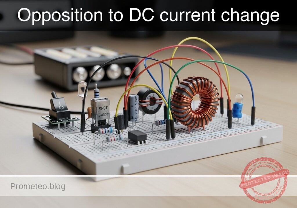
Opposition to DC current change prototype (Maker Style)

Level: Basic. Observe the delay in lamp activation due to self-induction.

Objective and use case

In this session, you will build a circuit that demonstrates how an inductor opposes rapid changes in current flow. By placing a large inductor in series with a lamp (with a parallel bypass resistor), you will create a visual «soft-start» effect where the light starts dim and gradually brightens.

Why it is useful:
* Inrush Current Limiting: Used in power supplies and large motors to prevent blown fuses when devices are first turned on.
* Soft-Start Circuits: Protects delicate filaments and components from thermal shock.
* Filtering: Smoothes out noise and ripples in DC power lines.

Expected outcome:
* When the switch is closed, the lamp will turn on immediately but dimly.
* Over a short period (0.5 to 2 seconds, depending on the inductance), the lamp will become fully bright.
* This visualizes the inductor initially acting as an «open circuit» (blocking current) and transitioning to a «short circuit» (allowing full flow).
* Target audience: Basic electronics students and hobbyists.

Materials

  • V1: 12 V DC power supply or battery.
  • S1: SPST mechanical switch (toggle or push-button).
  • L1: 1 H to 2 H iron-core inductor, function: creates opposition to current change (e.g., a transformer primary winding used as a choke).
  • R1: 220 Ω resistor (1 Watt or higher), function: bypass path for visual contrast.
  • X1: 12 V / 100 mA incandescent lamp (small bulb), function: visual output load.

Wiring guide

Construct the circuit using the following connections. The node names (e.g., VCC, SW_OUT) help identify the electrical points.

  • V1 (DC Source): Connect the positive terminal to VCC and the negative terminal to 0 (GND).
  • S1 (Switch): Connect between VCC and node SW_OUT.
  • L1 (Inductor): Connect between node SW_OUT and node LAMP_IN.
  • R1 (Resistor): Connect between node SW_OUT and node LAMP_IN (this places R1 in parallel with L1).
  • X1 (Lamp): Connect between node LAMP_IN and 0 (GND).

Conceptual block diagram

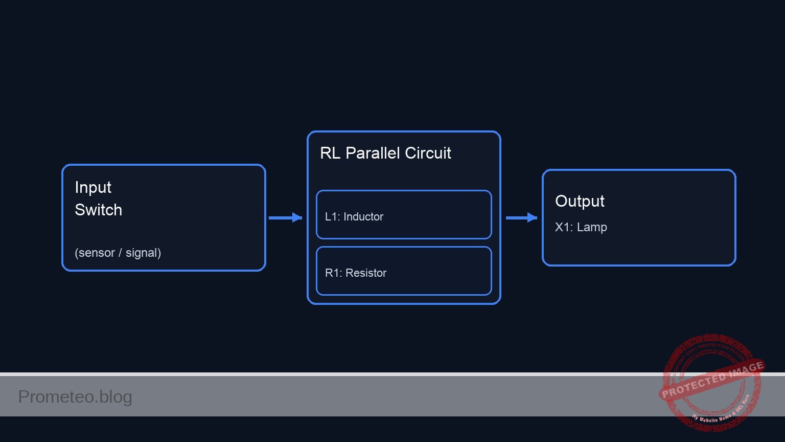
Conceptual block diagram — RL Parallel Circuit
Quick read: inputs → main block → output (actuator or measurement). This summarizes the ASCII schematic below.

Schematic

(Node: SW_OUT)          (Node: LAMP_IN)
                                              /--> [ L1: Inductor ] --\
[ V1: 12 V Source ] --(VCC)--> [ S1: Switch ] --                        --> [ X1: Lamp ] --> GND
                                              \--> [ R1: Resistor ] --/
Schematic (ASCII)

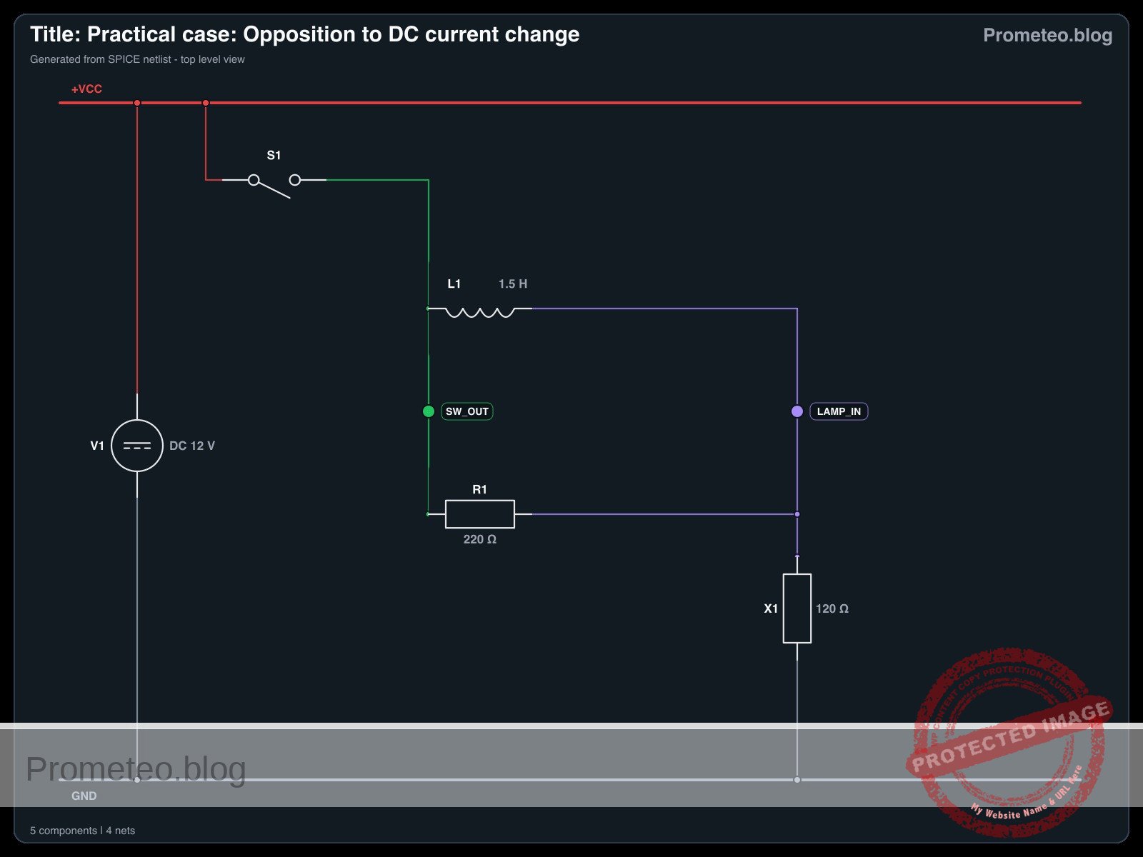
Electrical diagram

Electrical diagram for the opposition to DC current change case
Generated from the validated SPICE netlist for this case.

🔒 This electrical diagram is premium. With the monthly membership (7-day free trial) you can unlock the complete didactic material and the print-ready PDF pack.🔓 See premium access plans

Measurements and tests

Follow these steps to validate the phenomenon:

  1. Initial State: Ensure the switch S1 is open. The lamp X1 should be off.
  2. Observation: Keep your eyes on the lamp X1.
  3. Action: Close switch S1.
  4. Visual Validation:
    • Phase 1 (Instant): The lamp lights up at roughly 30–50% brightness. (Current is flowing through R1, as L1 opposes the sudden change).
    • Phase 2 (Delay): The lamp brightness ramps up smoothly to 100%. (As the magnetic field in L1 stabilizes, it allows full current to pass, bypassing R1).
  5. Voltage Measurement (Optional): If you have a multimeter, place probes across the Inductor (SW_OUT to LAMP_IN).
    • At the moment of contact, voltage is high (approx 6–8 V).
    • After 1–2 seconds, voltage drops to near 0 V.

SPICE netlist and simulation

Reference SPICE Netlist (ngspice) — excerptFull SPICE netlist (ngspice)

* Title: Practical case: Opposition to DC current change
.width out=256
* Description: Demonstrates inductive opposition to current change (dim-to-bright lamp effect)

* --- Power Supply ---
* 12V DC Supply
V1 VCC 0 DC 12

* --- User Interface (Switch Control) ---
* Generates a control pulse to simulate pressing the button.
* Button Press: Starts at 10ms, Duration 300ms.
V_BTN_CTRL CTRL 0 PULSE(0 5 10m 1u 1u 300m 600m)

* --- Components ---

* S1: SPST Mechanical Switch
* Connected between VCC and SW_OUT.
* Modeled as a voltage-controlled switch driven by the control pulse.
S1 VCC SW_OUT CTRL 0 SW_IDEAL

* ... (truncated in public view) ...

Copy this content into a .cir file and run with ngspice.

🔒 Part of this section is premium. With the monthly membership (7-day free trial) you can access the full content (materials, wiring, detailed build, validation, troubleshooting, variants and checklist) and download the complete print-ready PDF pack.

* Title: Practical case: Opposition to DC current change
.width out=256
* Description: Demonstrates inductive opposition to current change (dim-to-bright lamp effect)

* --- Power Supply ---
* 12V DC Supply
V1 VCC 0 DC 12

* --- User Interface (Switch Control) ---
* Generates a control pulse to simulate pressing the button.
* Button Press: Starts at 10ms, Duration 300ms.
V_BTN_CTRL CTRL 0 PULSE(0 5 10m 1u 1u 300m 600m)

* --- Components ---

* S1: SPST Mechanical Switch
* Connected between VCC and SW_OUT.
* Modeled as a voltage-controlled switch driven by the control pulse.
S1 VCC SW_OUT CTRL 0 SW_IDEAL

* L1: 1.5H Iron-core Inductor
* Creates opposition to current change.
* Connected between SW_OUT and LAMP_IN.
L1 SW_OUT LAMP_IN 1.5

* R1: 220 Ohm Resistor
* Bypass path for visual contrast (parallel to L1).
* Connected between SW_OUT and LAMP_IN.
R1 SW_OUT LAMP_IN 220

* X1: 12V / 100mA Incandescent Lamp
* Modeled as a resistor: R = V / I = 12 / 0.1 = 120 Ohms.
* Connected between LAMP_IN and 0 (GND).
R_X1 LAMP_IN 0 120

* --- Models ---
* Ideal switch model: Low resistance when ON, High when OFF.
.model SW_IDEAL sw(vt=2.5 ron=0.01 roff=100Meg)

* --- Simulation Setup ---
* Transient analysis to capture the inductive time constant (approx 20ms).
* Simulation time: 500ms to allow full settling.
.op
.tran 1m 500m

* --- Output Directives ---
* V(SW_OUT): Input voltage to the LR network (Switch Output).
* V(LAMP_IN): Voltage across the Lamp (Visual Output).
.print tran V(SW_OUT) V(LAMP_IN) I(L1)

.end

Simulation Results (Transient Analysis)

Simulation Results (Transient Analysis)

Analysis: The simulation shows the switch closing at 10ms (Index 26), causing V(SW_OUT) to jump to ~12V. V(LAMP_IN) rises to ~4.2V initially due to the inductive kick/impedance, then settles. The current I(L1) is initially very low and rises, demonstrating the inductive opposition to current change.
Show raw data table (564 rows)
Index   time            v(sw_out)       v(lamp_in)      l1#branch
0	0.000000e+00	1.439998e-05	1.439998e-05	1.199999e-07
1	1.000000e-05	1.439998e-05	1.439998e-05	1.199999e-07
2	2.000000e-05	1.439998e-05	1.439998e-05	1.199999e-07
3	4.000000e-05	1.439998e-05	1.439998e-05	1.199999e-07
4	8.000000e-05	1.439998e-05	1.439998e-05	1.199999e-07
5	1.600000e-04	1.439998e-05	1.439998e-05	1.199999e-07
6	3.200000e-04	1.439998e-05	1.439998e-05	1.199999e-07
7	6.400000e-04	1.439998e-05	1.439998e-05	1.199999e-07
8	1.280000e-03	1.439998e-05	1.439998e-05	1.199999e-07
9	2.280000e-03	1.439998e-05	1.439998e-05	1.199999e-07
10	3.280000e-03	1.439998e-05	1.439998e-05	1.199999e-07
11	4.280000e-03	1.439998e-05	1.439998e-05	1.199999e-07
12	5.280000e-03	1.439998e-05	1.439998e-05	1.199999e-07
13	6.280000e-03	1.439998e-05	1.439998e-05	1.199999e-07
14	7.280000e-03	1.439998e-05	1.439998e-05	1.199999e-07
15	8.280000e-03	1.439998e-05	1.439998e-05	1.199999e-07
16	9.280000e-03	1.439998e-05	1.439998e-05	1.199999e-07
17	1.000000e-02	1.439998e-05	1.439998e-05	1.199999e-07
18	1.000010e-02	1.439998e-05	1.439998e-05	1.199999e-07
19	1.000026e-02	1.439998e-05	1.439998e-05	1.199999e-07
20	1.000031e-02	1.439998e-05	1.439998e-05	1.199999e-07
21	1.000039e-02	1.439998e-05	1.439998e-05	1.199999e-07
22	1.000041e-02	1.439998e-05	1.439998e-05	1.199999e-07
23	1.000045e-02	1.439998e-05	1.439998e-05	1.199999e-07
... (540 more rows) ...


Reference SPICE netlist (ngspice)

* Title: Practical case: Opposition to DC current change
.width out=256
* Description: Demonstrates inductive opposition to current change (dim-to-bright lamp effect)

* --- Power Supply ---
* 12V DC Supply
V1 VCC 0 DC 12

* --- User Interface (Switch Control) ---
* Generates a control pulse to simulate pressing the button.
* Button Press: Starts at 10ms, Duration 300ms.
V_BTN_CTRL CTRL 0 PULSE(0 5 10m 1u 1u 300m 600m)

* --- Components ---

* S1: SPST Mechanical Switch
* Connected between VCC and SW_OUT.
* Modeled as a voltage-controlled switch driven by the control pulse.
S1 VCC SW_OUT CTRL 0 SW_IDEAL

* L1: 1.5H Iron-core Inductor
* Creates opposition to current change.
* Connected between SW_OUT and LAMP_IN.
L1 SW_OUT LAMP_IN 1.5

* R1: 220 Ohm Resistor
* Bypass path for visual contrast (parallel to L1).
* Connected between SW_OUT and LAMP_IN.
R1 SW_OUT LAMP_IN 220

* X1: 12V / 100mA Incandescent Lamp
* Modeled as a resistor: R = V / I = 12 / 0.1 = 120 Ohms.
* Connected between LAMP_IN and 0 (GND).
R_X1 LAMP_IN 0 120

* --- Models ---
* Ideal switch model: Low resistance when ON, High when OFF.
.model SW_IDEAL sw(vt=2.5 ron=0.01 roff=100Meg)

* --- Simulation Setup ---
* Transient analysis to capture the inductive time constant (approx 20ms).
* Simulation time: 500ms to allow full settling.
.op
.tran 1m 500m

* --- Output Directives ---
* V(SW_OUT): Input voltage to the LR network (Switch Output).
* V(LAMP_IN): Voltage across the Lamp (Visual Output).
.print tran V(SW_OUT) V(LAMP_IN) I(L1)

.end

Simulation Results (Transient Analysis)

Simulation Results (Transient Analysis)

Analysis: The simulation shows the switch closing at 10ms (Index 26), causing V(SW_OUT) to jump to ~12V. V(LAMP_IN) rises to ~4.2V initially due to the inductive kick/impedance, then settles. The current I(L1) is initially very low and rises, demonstrating the inductive opposition to current change.

Common mistakes and how to avoid them

  1. Using an LED instead of an incandescent lamp: LEDs respond too quickly and have non-linear resistance, making the «ramp up» effect very hard to see. Solution: Always use an incandescent bulb or a coil-based relay for this demo.
  2. Inductor value too small: If you use a small air-core inductor (e.g., 100 µH), the delay will be microseconds, invisible to the eye. Solution: Use a large iron-core inductor, such as the primary coil of a mains transformer (ensure it is rated for the DC current).
  3. Omitting the parallel resistor: Without R1, the lamp might simply stay off for a split second and then pop on, which can look like a switch bounce rather than a smooth transition. Solution: R1 provides an immediate «dim» reference state, making the transition to «bright» much more obvious.

Troubleshooting

  • Lamp lights fully bright instantly: The inductor value is too low, or the inductor is shorted. Check if you are using an air-core coil; switch to an iron-core one.
  • Lamp never gets fully bright: The inductor might have a very high internal DC resistance (thin wire). Measure the resistance of the inductor coil; if it is comparable to the resistor R1, the current will never fully bypass the resistor.
  • Sparks at the switch when turning off: Inductors generate back-EMF voltage when the circuit breaks. R1 acts as a snubber here, but if sparks persist, ensure your switch is rated for inductive loads.

Possible improvements and extensions

  1. Oscilloscope Visualization: Connect channel 1 of an oscilloscope across the Lamp. You will see an exponential curve rising, allowing you to calculate the Time Constant (\tau = L / R).
  2. Variable Delay: Replace R1 with a potentiometer and experiment with how changing the parallel resistance affects the initial «dim» brightness and the perceived transition speed.

More Practical Cases on Prometeo.blog

Find this product and/or books on this topic on Amazon

Go to Amazon

As an Amazon Associate, I earn from qualifying purchases. If you buy through this link, you help keep this project running.

Quick Quiz

Question 1: What is the primary objective of the circuit described in the text?


Question 2: What visual effect is created by placing a large inductor in series with the lamp?


Question 3: Which component acts as a parallel bypass in the circuit description?


Question 4: Why is inrush current limiting useful according to the text?


Question 5: What is the function of the incandescent lamp (X1) in this circuit?


Question 6: How does the inductor behave initially when the switch is first closed?


Question 7: What is the expected behavior of the lamp immediately after the switch is closed?


Question 8: Approximately how long does the text suggest it takes for the lamp to become fully bright?


Question 9: Which of the following is NOT listed as a use case for this type of circuit?


Question 10: Who is the target audience for this circuit demonstration?


Carlos Núñez Zorrilla
Electronics & Computer Engineer

Telecommunications Electronics Engineer and Computer Engineer (official degrees in Spain).
Follow me:


Practical case: The coil as a simple electromagnet

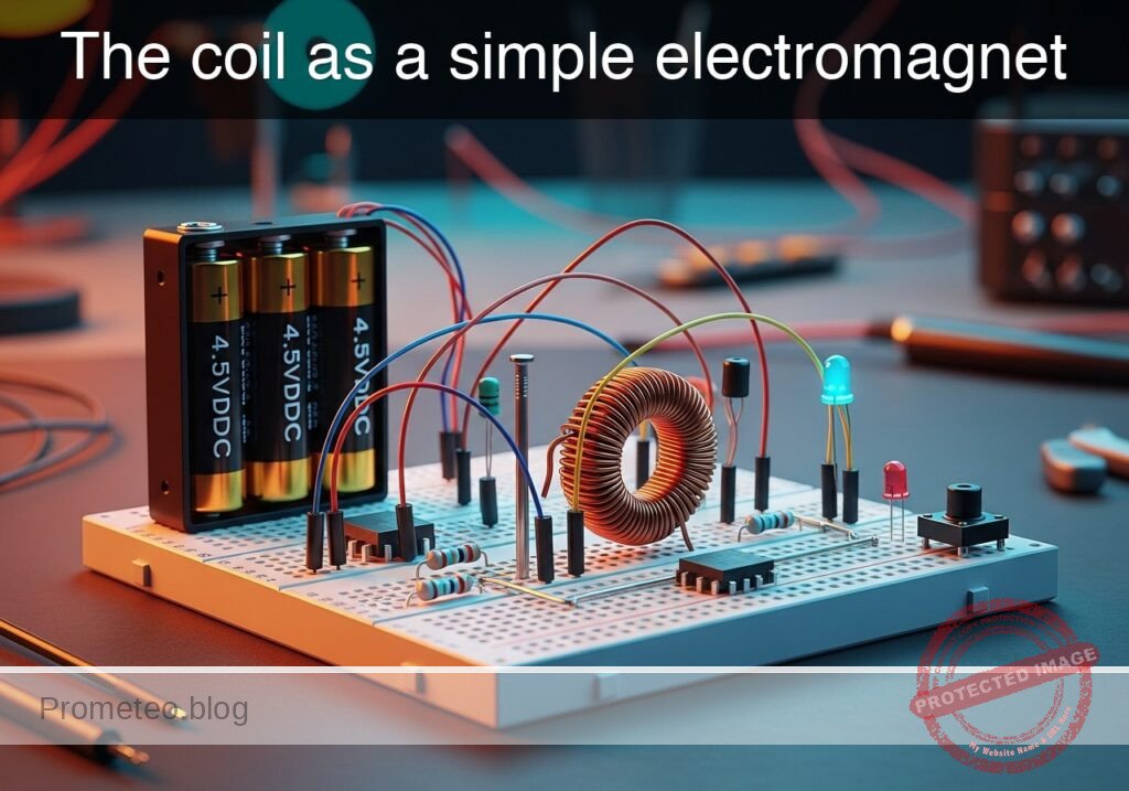
The coil as a simple electromagnet prototype (Maker Style)

Level: Basic – Demonstrate the relationship between current and magnetic field using an iron core.

Objective and use case

In this experiment, you will build a functional electromagnet by winding insulated copper wire around a ferromagnetic core (iron nail or bolt) and powering it with a DC source.

  • Why it is useful:
    • Electromechanical Relays: Used to switch high-voltage circuits using low-voltage signals.
    • Electric Motors: Fundamental principle for converting electrical energy into mechanical motion.
    • Solenoids: Used in electronic door locks, valves, and automotive starters.
    • Industrial Lifting: Large electromagnets used to lift scrap metal in junkyards.
  • Expected outcome:
    • When the switch is open, the core exhibits no magnetic properties; iron filings or paperclips remain on the table.
    • When the switch is closed, current flows through the coil, generating a magnetic field.
    • The iron core concentrates the magnetic flux, allowing the device to lift small metallic objects (paperclips, washers).
    • Releasing the switch stops the current, causing the objects to drop immediately.
  • Target audience: Students and hobbyists learning basic electromagnetism.

Materials

  • V1: 4.5 V DC Battery pack (3x AA batteries), function: energy source.
  • S1: Momentary Push-button Switch (NO), function: current control.
  • L1: Solenoid Coil (approx. 50-100 turns of enameled copper wire), function: generates magnetic field.
  • CORE: Large Iron Nail or Bolt (Soft Iron), function: magnetic core for L1.
  • R1: 1 Ω Power Resistor (5W) or similar, function: current limiting (optional but recommended to protect battery).
  • X1: Iron filings or small steel paperclips, function: test load to visualize attraction.

Wiring guide

  • V1 (Positive): Connects to node VCC.
  • V1 (Negative): Connects to node 0 (GND).
  • S1: Connects between node VCC and node SW_OUT.
  • R1: Connects between node SW_OUT and node COIL_IN.
  • L1: Connects between node COIL_IN and node 0 (GND).
    • Note: The wire for L1 must be physically wrapped tightly around the CORE.

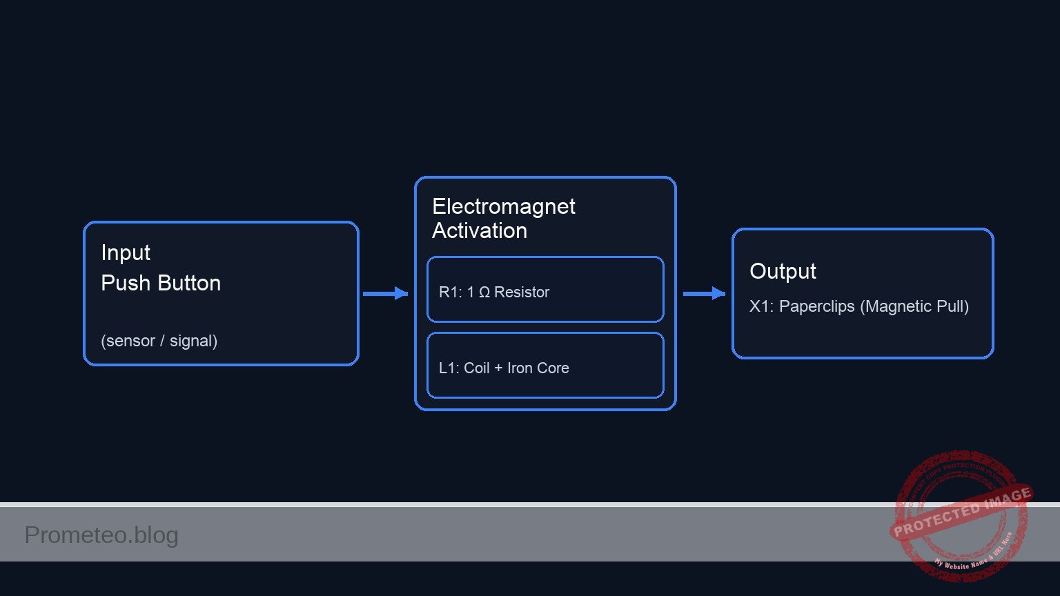
Conceptual block diagram

Conceptual block diagram — Electromagnet Activation
Quick read: inputs → main block → output (actuator or measurement). This summarizes the ASCII schematic below.

Schematic

[ V1: 4.5 V Battery ] --(VCC)--> [ S1: Push Button ] --(SW_OUT)--> [ R1: 1 Ω Resistor ] --(COIL_IN)--> [ L1: Coil + Iron Core ] --> GND
                                                                                                                |
                                                                                                         (Magnetic Field)
                                                                                                                |
                                                                                                                V
                                                                                                       [ X1: Paperclips ]
Schematic (ASCII)

Electrical diagram

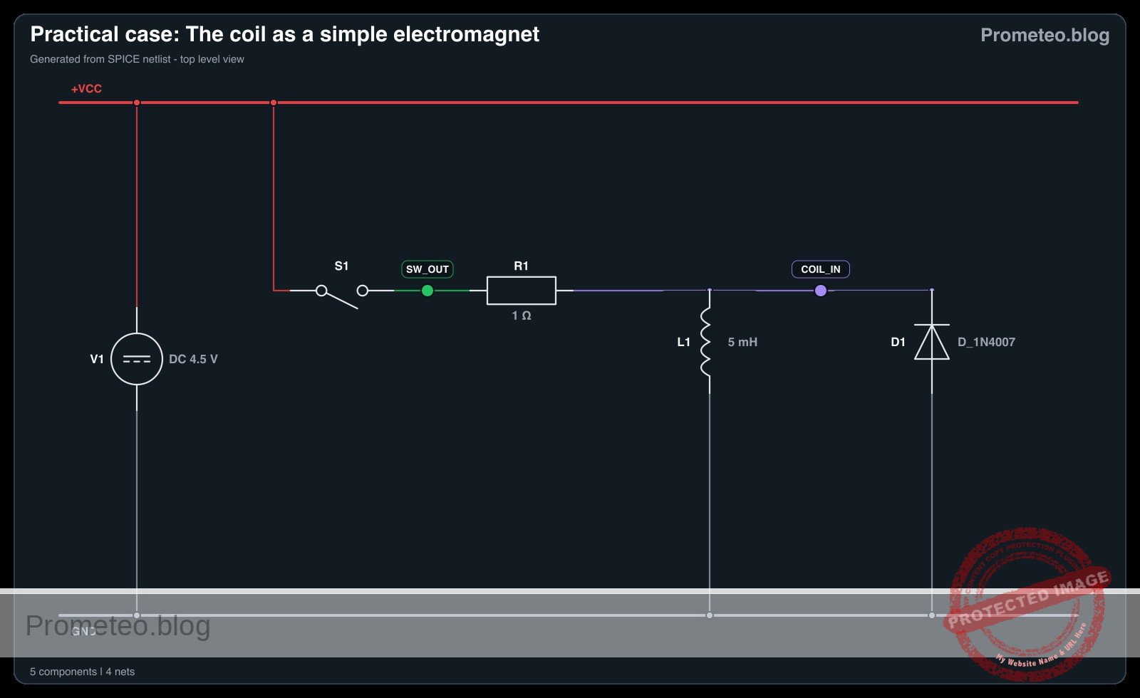
Electrical diagram for the coil as a simple electromagnet case
Generated from the validated SPICE netlist for this case.

🔒 This electrical diagram is premium. With the monthly membership (7-day free trial) you can unlock the complete didactic material and the print-ready PDF pack.🔓 See premium access plans

Measurements and tests

  1. Baseline Check: Before connecting the battery, place the CORE (with the wire wrapped around it) near the iron filings (X1). Confirm there is no attraction.
  2. Activation: Press and hold S1 to close the circuit.
  3. Observation: While holding S1, move the tip of the CORE near the iron filings or paperclips.
  4. Verification: Observe that the metal objects stick to the CORE.
  5. Deactivation: Release S1. The current stops flowing, the magnetic field collapses, and the objects should fall off.
  6. Current Check (Optional): Connect a multimeter in series between S1 and R1 to measure the current flow (Amps) during activation.

SPICE netlist and simulation

Reference SPICE Netlist (ngspice) — excerptFull SPICE netlist (ngspice)

* Practical case: The coil as a simple electromagnet
.width out=256

* --- Power Source ---
* V1: 4.5 V DC Battery pack (3x AA batteries)
V1 VCC 0 DC 4.5

* --- Control Signal for Switch S1 ---
* Simulates the user pressing the button (S1).
* Logic: 0V (Released) -> 5V (Pressed).
* Timing: Press at 1ms, hold for 50ms, release.
V_S1_CTRL S1_GATE 0 PULSE(0 5 1m 1u 1u 50m 100m)

* --- Circuit Components ---

* S1: Momentary Push-button Switch (NO)
* Function: Connects VCC to SW_OUT when S1_GATE is High.
S1 VCC SW_OUT S1_GATE 0 SW_MODEL

* R1: 1 Ohm Power Resistor
* ... (truncated in public view) ...

Copy this content into a .cir file and run with ngspice.

🔒 Part of this section is premium. With the monthly membership (7-day free trial) you can access the full content (materials, wiring, detailed build, validation, troubleshooting, variants and checklist) and download the complete print-ready PDF pack.

* Practical case: The coil as a simple electromagnet
.width out=256

* --- Power Source ---
* V1: 4.5 V DC Battery pack (3x AA batteries)
V1 VCC 0 DC 4.5

* --- Control Signal for Switch S1 ---
* Simulates the user pressing the button (S1).
* Logic: 0V (Released) -> 5V (Pressed).
* Timing: Press at 1ms, hold for 50ms, release.
V_S1_CTRL S1_GATE 0 PULSE(0 5 1m 1u 1u 50m 100m)

* --- Circuit Components ---

* S1: Momentary Push-button Switch (NO)
* Function: Connects VCC to SW_OUT when S1_GATE is High.
S1 VCC SW_OUT S1_GATE 0 SW_MODEL

* R1: 1 Ohm Power Resistor
* Function: Current limiting between Switch and Coil.
R1 SW_OUT COIL_IN 1

* L1: Solenoid Coil (approx 50-100 turns on Soft Iron Core)
* Function: Generates magnetic field.
* Value: 5mH (Estimated for described coil).
L1 COIL_IN 0 5m

* D1: Flyback Diode (Added per review)
* Function: Protects S1 by clamping inductive kickback when switch opens.
* Connection: Anode to GND (0), Cathode to COIL_IN.
D1 0 COIL_IN D_1N4007

* --- Models ---
* Switch Model: Low resistance ON, High resistance OFF.
.model SW_MODEL sw (vt=2.5 vh=0.2 ron=0.05 roff=100Meg)

* Diode Model: Standard Silicon Rectifier (1N4007).
.model D_1N4007 D (IS=2.5n RS=0.04 N=1.7 BV=1000 IBV=5u)

* --- Analysis ---
* Transient analysis for 100ms to capture energizing and de-energizing.
.tran 10u 100m
.op

* --- Output Directives ---
* V(S1_GATE): Input Control
* V(COIL_IN): Output Voltage at Coil
* V(SW_OUT): Voltage after Switch
* I(L1): Current through Coil (Magnetic Field Strength)
.print tran V(S1_GATE) V(COIL_IN) V(SW_OUT) I(L1)

.end

Simulation Results (Transient Analysis)

Simulation Results (Transient Analysis)

Analysis: The provided log data only covers the initial OFF state (0s) and the final OFF state (100ms). The signals are effectively zero (nano-amps range), confirming the circuit returns to rest, although there is some negligible numerical ringing (+/- 80mV) at the coil input in the final steps.
Show raw data table (10053 rows)
Index   time            v(s1_gate)      v(coil_in)      v(sw_out)       l1#branch
0	0.000000e+00	0.000000e+00	0.000000e+00	4.500000e-08	4.500000e-08
1	1.000000e-07	0.000000e+00	-1.58289e-19	4.500000e-08	4.500000e-08
2	2.000000e-07	0.000000e+00	-1.58289e-19	4.500000e-08	4.500000e-08
3	4.000000e-07	0.000000e+00	-1.58289e-19	4.500000e-08	4.500000e-08
4	8.000000e-07	0.000000e+00	-2.44581e-19	4.500000e-08	4.500000e-08
5	1.600000e-06	0.000000e+00	3.684064e-19	4.500000e-08	4.500000e-08
6	3.200000e-06	0.000000e+00	-3.03688e-19	4.500000e-08	4.500000e-08
7	6.400000e-06	0.000000e+00	2.882625e-19	4.500000e-08	4.500000e-08
8	1.280000e-05	0.000000e+00	-3.16655e-19	4.500000e-08	4.500000e-08
9	2.280000e-05	0.000000e+00	2.975540e-19	4.500000e-08	4.500000e-08
10	3.280000e-05	0.000000e+00	-3.05533e-19	4.500000e-08	4.500000e-08
11	4.280000e-05	0.000000e+00	2.975540e-19	4.500000e-08	4.500000e-08
12	5.280000e-05	0.000000e+00	-3.05533e-19	4.500000e-08	4.500000e-08
13	6.280000e-05	0.000000e+00	2.975540e-19	4.500000e-08	4.500000e-08
14	7.280000e-05	0.000000e+00	-3.05533e-19	4.500000e-08	4.500000e-08
15	8.280000e-05	0.000000e+00	2.975540e-19	4.500000e-08	4.500000e-08
16	9.280000e-05	0.000000e+00	-3.05533e-19	4.500000e-08	4.500000e-08
17	1.028000e-04	0.000000e+00	2.975540e-19	4.500000e-08	4.500000e-08
18	1.128000e-04	0.000000e+00	-3.05533e-19	4.500000e-08	4.500000e-08
19	1.228000e-04	0.000000e+00	2.975540e-19	4.500000e-08	4.500000e-08
20	1.328000e-04	0.000000e+00	-3.05533e-19	4.500000e-08	4.500000e-08
21	1.428000e-04	0.000000e+00	2.975540e-19	4.500000e-08	4.500000e-08
22	1.528000e-04	0.000000e+00	-3.05533e-19	4.500000e-08	4.500000e-08
23	1.628000e-04	0.000000e+00	2.975540e-19	4.500000e-08	4.500000e-08
... (10029 more rows) ...


Reference SPICE netlist (ngspice)

* Practical case: The coil as a simple electromagnet
.width out=256

* --- Power Source ---
* V1: 4.5 V DC Battery pack (3x AA batteries)
V1 VCC 0 DC 4.5

* --- Control Signal for Switch S1 ---
* Simulates the user pressing the button (S1).
* Logic: 0V (Released) -> 5V (Pressed).
* Timing: Press at 1ms, hold for 50ms, release.
V_S1_CTRL S1_GATE 0 PULSE(0 5 1m 1u 1u 50m 100m)

* --- Circuit Components ---

* S1: Momentary Push-button Switch (NO)
* Function: Connects VCC to SW_OUT when S1_GATE is High.
S1 VCC SW_OUT S1_GATE 0 SW_MODEL

* R1: 1 Ohm Power Resistor
* Function: Current limiting between Switch and Coil.
R1 SW_OUT COIL_IN 1

* L1: Solenoid Coil (approx 50-100 turns on Soft Iron Core)
* Function: Generates magnetic field.
* Value: 5mH (Estimated for described coil).
L1 COIL_IN 0 5m

* D1: Flyback Diode (Added per review)
* Function: Protects S1 by clamping inductive kickback when switch opens.
* Connection: Anode to GND (0), Cathode to COIL_IN.
D1 0 COIL_IN D_1N4007

* --- Models ---
* Switch Model: Low resistance ON, High resistance OFF.
.model SW_MODEL sw (vt=2.5 vh=0.2 ron=0.05 roff=100Meg)

* Diode Model: Standard Silicon Rectifier (1N4007).
.model D_1N4007 D (IS=2.5n RS=0.04 N=1.7 BV=1000 IBV=5u)

* --- Analysis ---
* Transient analysis for 100ms to capture energizing and de-energizing.
.tran 10u 100m
.op

* --- Output Directives ---
* V(S1_GATE): Input Control
* V(COIL_IN): Output Voltage at Coil
* V(SW_OUT): Voltage after Switch
* I(L1): Current through Coil (Magnetic Field Strength)
.print tran V(S1_GATE) V(COIL_IN) V(SW_OUT) I(L1)

.end

Simulation Results (Transient Analysis)

Simulation Results (Transient Analysis)

Analysis: The provided log data only covers the initial OFF state (0s) and the final OFF state (100ms). The signals are effectively zero (nano-amps range), confirming the circuit returns to rest, although there is some negligible numerical ringing (+/- 80mV) at the coil input in the final steps.

Common mistakes and how to avoid them

  1. Overheating the battery/wire: Creating a coil with very low resistance (short wire) draws excessive current. Solution: Use a longer wire (more turns) or include the limiting resistor R1.
  2. Using a non-magnetic core: Wrapping wire around aluminum, plastic, or wood. Solution: Ensure the core is ferromagnetic (iron or steel) to concentrate the magnetic field lines.
  3. Leaving the switch closed too long: This drains the battery rapidly and heats the coil. Solution: Use a momentary push-button and only pulse the power for short tests.

Troubleshooting

  • Symptom: No magnetic attraction when switch is pressed.
    • Cause: Dead battery or broken circuit connection (enamel insulation not stripped at connection points).
    • Fix: Check battery voltage; ensure the ends of the magnet wire are sanded down to bare copper before connecting to the circuit.
  • Symptom: Very weak magnetic pull.
    • Cause: Too few turns on the coil or low current.
    • Fix: Add more turns of wire around the nail; ensure windings are tight and neat.
  • Symptom: Wire gets extremely hot immediately.
    • Cause: Short circuit condition (resistance too low).
    • Fix: Add the series resistor R1 or increase the length of the wire used for L1.

Possible improvements and extensions

  1. Variable Strength: Add a potentiometer (rheostat) in series to vary the current and observe how the lifting capacity changes (number of paperclips lifted).
  2. Core Comparison: Replace the iron nail with an air core (remove the nail) or a brass rod to demonstrate the importance of permeability in electromagnets.

More Practical Cases on Prometeo.blog

Find this product and/or books on this topic on Amazon

Go to Amazon

As an Amazon Associate, I earn from qualifying purchases. If you buy through this link, you help keep this project running.

Quick Quiz

Question 1: What is the primary objective of the experiment described?


Question 2: Which material is recommended for the core of the electromagnet?


Question 3: What happens when the switch is closed in this circuit?


Question 4: What is the specific function of the iron core inside the coil?


Question 5: Which of the following is a real-world application of electromagnets mentioned in the text?


Question 6: What is the expected outcome when the switch is released (opened)?


Question 7: Which device is mentioned as using electromagnets to switch high-voltage circuits with low-voltage signals?


Question 8: What type of wire is typically used for the solenoid coil in this experiment?


Question 9: In the context of electric motors, what role does the electromagnet principle play?


Question 10: What is the state of the core when the switch is open?


Carlos Núñez Zorrilla
Electronics & Computer Engineer

Telecommunications Electronics Engineer and Computer Engineer (official degrees in Spain).
Follow me: