Level: Basic. Objective: Build a circuit that activates an LED when light levels drop.
Objective and use case
In this practical case, you will design and assemble a light-sensing circuit that automatically turns on an LED when the environment becomes dark. This circuit uses a photodiode to control an NPN transistor acting as a switch.
- Real-world applications:
- Automatic street lighting systems.
- Emergency corridor lights that activate during power outages (if light absent).
- Battery-saving garden solar lights.
- Security systems triggered by shadows or obstruction of light beams.
- Expected outcome:
- Bright light: The LED remains OFF; the voltage at the transistor base is low.
- Darkness: The LED turns ON; the voltage at the transistor base rises above 0.7 V.
- Transition: The circuit reacts to the absence of light (dark sensor logic).
- Target audience: Beginners and electronics students.
Materials
- V1: 5 V DC supply, function: main power source.
- R1: 100 kΩ resistor, function: base pull-up resistor (sets sensitivity).
- R2: 330 Ω resistor, function: LED current limiting.
- D1: Generic silicon photodiode, function: light sensor.
- Q1: 2N2222 (or BC547) NPN Transistor, function: electronic switch.
- D2: Red LED, function: visual output indicator.
Wiring guide
This guide uses specific node names to define the connections clearly.
* Nodes defined: VCC (5 V), GND (0 V), V_BASE (Control voltage), V_COL (Collector voltage).
- V1 (Source): Connect positive terminal to
VCCand negative terminal toGND. - R1 (Bias): Connect between
VCCandV_BASE. - D1 (Photodiode):
- Connect the Cathode to
V_BASE. - Connect the Anode to
GND. - Note: The photodiode is used in reverse bias mode.
- Connect the Cathode to
- Q1 (Transistor):
- Connect the Base to
V_BASE. - Connect the Emitter to
GND. - Connect the Collector to
V_COL.
- Connect the Base to
- R2 & D2 (Output Loop):
- Connect R2 between
VCCand the Anode of D2. - Connect the Cathode of D2 to
V_COL(the Collector of Q1).
- Connect R2 between
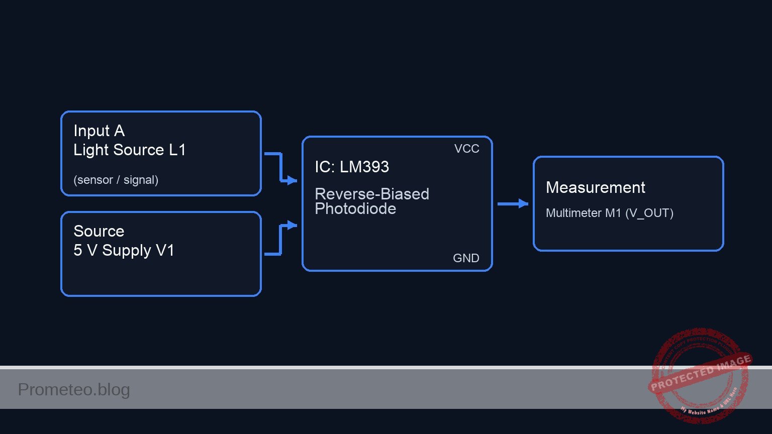
Conceptual block diagram

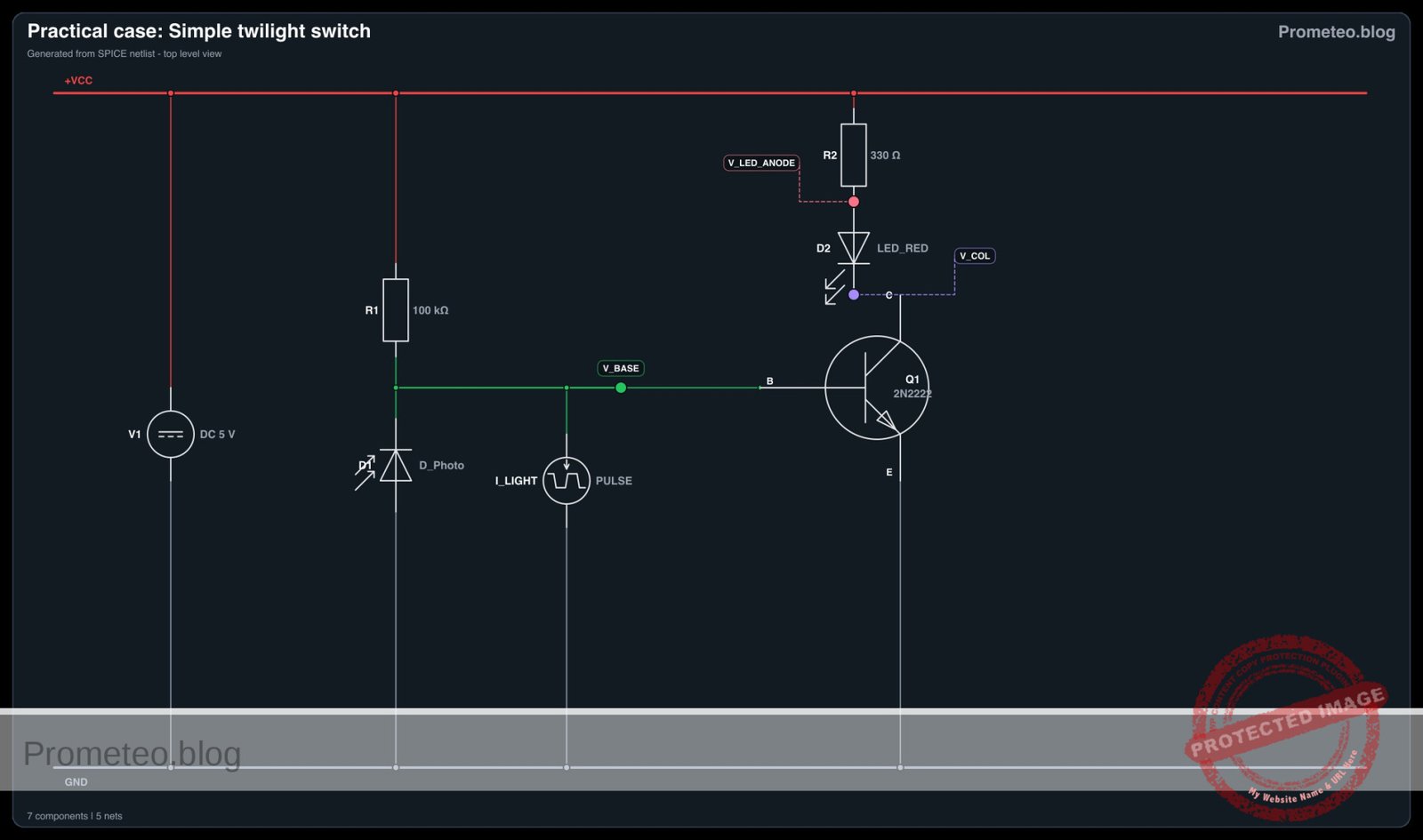
Schematic
[ INPUT / SENSING ]                     [ LOGIC / SWITCHING ]                   [ OUTPUT / LOAD ]

      [ VCC (5 V) ]                                                                       [ VCC (5 V) ]
           |                                                                                  |
           |                                                                                  |
           v                                                                                  v
    [ R1: 100k Bias ] --(Pull Up)--+                                                  [ R2: 330 Ohm ]
                                   |                                                          |
                                   |                                                          |
                                (V_BASE)                                                      v
                                   |                                                    [ D2: Red LED ]
                                   |                                                          |
                                   +--(Control Sig)--> [ Q1: NPN Base ]                       |
                                   |                   [              ]                       |
                                   |                   [ Q1 Collector ] <--(Sink Current)-----+
    [ D1: Photodiode ] --(Sensor)--+                   [              ]                 (V_COL Node)
    (Reverse Biased)               |                   [ Q1 Emitter   ]
           |                       |                          |
           |                       |                          |
           v                       |                          v
        [ GND ]                    +---------------------> [ GND ]
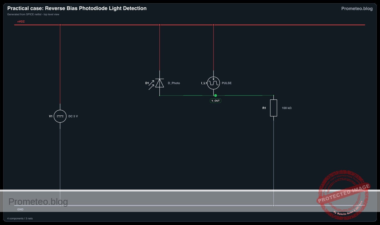
Electrical diagram
Measurements and tests
Perform the following validation steps using a multimeter to ensure the circuit works as intended.
- Check Supply Voltage:
- Measure between
VCCandGND. It should read approximately 5 V.
- Measure between
- Test Light Condition (LED OFF):
- Shine a bright light directly on the photodiode D1.
- Measure voltage at
V_BASE. It should be low (typically < 0.5 V) because the photodiode conducts current to ground. - Observe D2 (LED). It should be OFF.
- Measure voltage at
V_COL. It should be close toVCC(High) as the transistor is in cutoff.
- Test Dark Condition (LED ON):
- Cover D1 completely with your hand or a dark cap.
- Measure voltage at
V_BASE. It should rise above 0.6 V – 0.7 V. - Observe D2 (LED). It should turn ON.
- Measure voltage at
V_COL. It should drop to near 0 V (saturation voltage ~0.2 V).
SPICE netlist and simulation
Reference SPICE Netlist (ngspice) — excerptFull SPICE netlist (ngspice)
* Practical case: Simple twilight switch

* --- Power Supply ---
* V1: 5 V DC supply
V1 VCC 0 DC 5

* --- Input Stage (Light Sensor) ---
* R1: 100 kΩ resistor (Base pull-up)
* Connect between VCC and V_BASE
R1 VCC V_BASE 100k

* D1: Generic silicon photodiode
* Connect the Cathode to V_BASE, Anode to GND (Reverse Bias)
* SPICE Syntax: Dname Anode Cathode Model
D1 0 V_BASE D_GENERIC

* OPTICAL STIMULUS SIMULATION
* The photodiode generates a photocurrent flowing from Cathode to Anode
* (Reverse current) proportional to light intensity.
* We simulate this with a Current Source (I_LIGHT) in parallel with D1.
* ... (truncated in public view) ...
Copy this content into a .cir file and run with ngspice.
* Practical case: Simple twilight switch

* --- Power Supply ---
* V1: 5 V DC supply
V1 VCC 0 DC 5

* --- Input Stage (Light Sensor) ---
* R1: 100 kΩ resistor (Base pull-up)
* Connect between VCC and V_BASE
R1 VCC V_BASE 100k

* D1: Generic silicon photodiode
* Connect the Cathode to V_BASE, Anode to GND (Reverse Bias)
* SPICE Syntax: Dname Anode Cathode Model
D1 0 V_BASE D_GENERIC

* OPTICAL STIMULUS SIMULATION
* The photodiode generates a photocurrent flowing from Cathode to Anode
* (Reverse current) proportional to light intensity.
* We simulate this with a Current Source (I_LIGHT) in parallel with D1.
* Logic:
*   0uA = Dark (Night) -> Base High -> Q1 ON -> LED ON
*   100uA = Light (Day) -> Base Low -> Q1 OFF -> LED OFF
* Waveform: Dark (0uA) transitioning to Light (100uA)
I_LIGHT V_BASE 0 PULSE(0 100u 100u 100u 100u 2m 5m)

* --- Switching Stage ---
* Q1: 2N2222 NPN Transistor
* Base to V_BASE, Emitter to GND, Collector to V_COL
* SPICE Syntax: Qname Collector Base Emitter Model
Q1 V_COL V_BASE 0 2N2222

* --- Output Stage ---
* R2: 330 Ω resistor
* Connect between VCC and the Anode of D2 (Node V_LED_ANODE)
R2 VCC V_LED_ANODE 330

* D2: Red LED
* Connect Anode to V_LED_ANODE, Cathode to V_COL
D2 V_LED_ANODE V_COL LED_RED

* --- Models ---
* Standard NPN Transistor Model
.model 2N2222 NPN (IS=1E-14 VAF=100 BF=200 IKF=0.3 XTB=1.5 BR=3 CJC=8E-12 CJE=25E-12 TR=46.91E-9 TF=411.1E-12 ITF=0.6 VTF=1.7 XTF=3 RB=10 RC=1 RE=0.1)

* Generic Red LED Model (Approx 1.8V-2V drop)
.model LED_RED D (IS=93.2p RS=42m N=3.73 BV=5 IBV=10u CJO=2.97p VJ=0.75 M=0.333 TT=4.32u)

* Generic Silicon Diode Model for Photodiode (Dark characteristics)
.model D_GENERIC D (IS=1N N=1 RS=0.1)

* --- Analysis Directives ---
* Transient analysis to show the switching behavior
.tran 10u 5m

* Print required voltages to verify operation
* V(V_BASE): Sensor voltage (High = Dark, Low = Light)
* V(V_COL): Output state (Low = LED ON, High/Floating = LED OFF)
.print tran V(V_BASE) V(V_COL)

.op
.end
Simulation Results (Transient Analysis)

Show raw data table (534 rows)
Index   time            v(v_base)       v(v_col)
0	0.000000e+00	7.119659e-01	4.863696e-01
1	1.000000e-07	7.119659e-01	4.863696e-01
2	2.000000e-07	7.119659e-01	4.863696e-01
3	4.000000e-07	7.119659e-01	4.863696e-01
4	8.000000e-07	7.119659e-01	4.863696e-01
5	1.600000e-06	7.119659e-01	4.863696e-01
6	3.200000e-06	7.119659e-01	4.863696e-01
7	6.400000e-06	7.119659e-01	4.863696e-01
8	1.280000e-05	7.119659e-01	4.863696e-01
9	2.280000e-05	7.119659e-01	4.863696e-01
10	3.280000e-05	7.119659e-01	4.863696e-01
11	4.280000e-05	7.119659e-01	4.863696e-01
12	5.280000e-05	7.119659e-01	4.863696e-01
13	6.280000e-05	7.119659e-01	4.863696e-01
14	7.280000e-05	7.119659e-01	4.863696e-01
15	8.280000e-05	7.119659e-01	4.863696e-01
16	9.280000e-05	7.119659e-01	4.863696e-01
17	1.000000e-04	7.119659e-01	4.863696e-01
18	1.006859e-04	7.117420e-01	5.075675e-01
19	1.020576e-04	7.110644e-01	5.716214e-01
20	1.044620e-04	7.094358e-01	7.222583e-01
21	1.068767e-04	7.077111e-01	8.743413e-01
22	1.096009e-04	7.056321e-01	1.048175e+00
23	1.150494e-04	7.009675e-01	1.400214e+00
... (510 more rows) ...
Reference SPICE netlist (ngspice)
* Practical case: Simple twilight switch

* --- Power Supply ---
* V1: 5 V DC supply
V1 VCC 0 DC 5

* --- Input Stage (Light Sensor) ---
* R1: 100 kΩ resistor (Base pull-up)
* Connect between VCC and V_BASE
R1 VCC V_BASE 100k

* D1: Generic silicon photodiode
* Connect the Cathode to V_BASE, Anode to GND (Reverse Bias)
* SPICE Syntax: Dname Anode Cathode Model
D1 0 V_BASE D_GENERIC

* OPTICAL STIMULUS SIMULATION
* The photodiode generates a photocurrent flowing from Cathode to Anode
* (Reverse current) proportional to light intensity.
* We simulate this with a Current Source (I_LIGHT) in parallel with D1.
* Logic:
*   0uA = Dark (Night) -> Base High -> Q1 ON -> LED ON
*   100uA = Light (Day) -> Base Low -> Q1 OFF -> LED OFF
* Waveform: Dark (0uA) transitioning to Light (100uA)
I_LIGHT V_BASE 0 PULSE(0 100u 100u 100u 100u 2m 5m)

* --- Switching Stage ---
* Q1: 2N2222 NPN Transistor
* Base to V_BASE, Emitter to GND, Collector to V_COL
* SPICE Syntax: Qname Collector Base Emitter Model
Q1 V_COL V_BASE 0 2N2222

* --- Output Stage ---
* R2: 330 Ω resistor
* Connect between VCC and the Anode of D2 (Node V_LED_ANODE)
R2 VCC V_LED_ANODE 330

* D2: Red LED
* Connect Anode to V_LED_ANODE, Cathode to V_COL
D2 V_LED_ANODE V_COL LED_RED

* --- Models ---
* Standard NPN Transistor Model
.model 2N2222 NPN (IS=1E-14 VAF=100 BF=200 IKF=0.3 XTB=1.5 BR=3 CJC=8E-12 CJE=25E-12 TR=46.91E-9 TF=411.1E-12 ITF=0.6 VTF=1.7 XTF=3 RB=10 RC=1 RE=0.1)

* Generic Red LED Model (Approx 1.8V-2V drop)
.model LED_RED D (IS=93.2p RS=42m N=3.73 BV=5 IBV=10u CJO=2.97p VJ=0.75 M=0.333 TT=4.32u)

* Generic Silicon Diode Model for Photodiode (Dark characteristics)
.model D_GENERIC D (IS=1N N=1 RS=0.1)

* --- Analysis Directives ---
* Transient analysis to show the switching behavior
.tran 10u 5m

* Print required voltages to verify operation
* V(V_BASE): Sensor voltage (High = Dark, Low = Light)
* V(V_COL): Output state (Low = LED ON, High/Floating = LED OFF)
.print tran V(V_BASE) V(V_COL)

.op
.end
Simulation Results (Transient Analysis)
Common mistakes and how to avoid them
- Reversing the Photodiode:
- Error: Connecting the Anode to Base and Cathode to Ground.
- Result: The diode acts like a standard forward-biased diode, clamping the Base to ~0.7 V permanently or conducting fully, preventing the switching logic.
- Solution: Ensure the Cathode (marked with a line or flat side) connects to the positive side (Base) for reverse bias operation.
- Incorrect Transistor Pinout:
- Error: Swapping Collector and Emitter on the 2N2222.
- Result: The gain is significantly reduced, and the LED may not turn on fully or the transistor might overheat.
- Solution: Verify the pinout (E-B-C) in the datasheet before insertion.
- Wrong Resistor Value for R1:
- Error: Using a very low value (e.g., 1 kΩ) for R1.
- Result: The photodiode current cannot pull the voltage down enough in bright light, keeping the LED ON permanently.
- Solution: Use a high value (100 kΩ to 330 kΩ) to allow the small photocurrent to control the voltage divider effectively.
Troubleshooting
- Symptom: LED is always ON, even in bright light.
- Cause: R1 is too small, or the ambient light is not strong enough to generate sufficient photocurrent.
- Fix: Increase R1 to 220 kΩ or 330 kΩ, or bring the light source closer.
- Symptom: LED is always OFF, even in total darkness.
- Cause: Photodiode is shorted, R1 is open, or Transistor is blown.
- Fix: Check continuity on R1. Remove D1; if LED turns on, D1 was shorted or installed backward (forward biased).
- Symptom: LED glows dimly in the dark.
- Cause: Q1 is not fully saturating.
- Fix: Decrease R2 slightly (ensure it stays above 220 Ω) or check if V1 is actually 5 V.
Possible improvements and extensions
- Sensitivity Adjustment: Replace R1 with a 500 kΩ potentiometer (in series with a 10 kΩ safety resistor) to manually tune the light level at which the LED triggers.
- Hysteresis/Clean Switching: Add a second transistor or a Schmitt Trigger (e.g., 74HC14) between the photodiode node and the driver transistor to prevent the LED from flickering at the «twilight» threshold.
More Practical Cases on Prometeo.blog
Find this product and/or books on this topic on Amazon
As an Amazon Associate, I earn from qualifying purchases. If you buy through this link, you help keep this project running.
Quick Quiz

Telecommunications Electronics Engineer and Computer Engineer (official degrees in Spain).