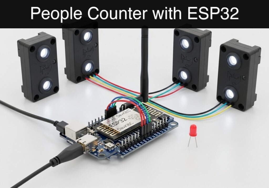
Practical case: People Counter with ESP32

Practical case: People Counter with ESP32 — hero

Objective and use case

What you’ll build: You will build a directional doorway people counter using dual infrared (IR) break-beam sensors to track individuals entering and exiting a room, broadcasting the real-time occupancy count over Bluetooth Low Energy (BLE).

Why it matters / Use cases

  • HVAC & Energy Optimization: Dynamically adjust climate control based on actual room occupancy, reducing energy waste by up to 20%.
  • Usage-based Maintenance: Trigger janitorial alerts automatically after a specific threshold (e.g., 50 entries) instead of relying on inefficient fixed schedules.
  • Retail & Space Analytics: Track peak visitor hours and correlate footfall with sales data, or monitor conference room utilization to optimize building layout.

Expected outcome

  • A deployed edge device accurately tracking directional movement with <50ms sensor polling latency.
  • Real-time BLE advertising of current room occupancy at a 1Hz update rate with minimal power consumption.
  • Robust debouncing logic that ignores partial crossings or false triggers to maintain an accurate count.

Audience: IoT Developers, Facility Managers, Makers; Level: Intermediate

Architecture/flow: Dual IR Break-Beam Sensors → Microcontroller GPIO Interrupts → Directional Counting Logic → BLE Advertisement → Gateway/Dashboard

Educational validation note

Before publication, this case passed the Prometeo automated validation gate with status PASS. For this ESP32 DevKitC profile, the project was checked as a PlatformIO project: the validator extracted platformio.ini and src/main.cpp, created a temporary project and ran pio run against platform = espressif32, board = esp32dev and framework = arduino. It also checked article structure, copy/paste-safe ASCII command options, and unsupported stacks such as direct ESP-IDF or non-scoped ESP32 boards.

Published validation evidence

  • Automatic result: PASS.
  • Parsed structure: 3 sections, 3 tables and 2 code blocks detected before publication.
  • Checked code: 1 PlatformIO config + 1 ESP32 source/pio run.
  • Supported catalog: the article text was checked against Prometeo’s validation-capable device profiles, and unsupported stacks block publication.
  • Report findings: no blocking findings.

This validation confirms syntax and tool compatibility for the published code, but it does not replace physical testing on your exact ESP32 DevKitC board, wiring, power supply and local WiFi environment.

Educational safety note

This prototype is designed strictly for educational and basic monitoring purposes. It must not be used for critical capacity enforcement, fire code compliance, emergency evacuation tracking, or security access control. The IR sensors used in standard hobby kits are eye-safe, but care should be taken to ensure wires traversing a doorway do not create a tripping hazard. If deploying in a real environment, secure all wiring safely and use proper enclosures.

Conceptual block diagram

High-level view: what enters the system, what each block processes, and what comes out.

Functional architecture

Local button

ESP32 BLE

Advertising packet

Status LED

Phone scanner

Conceptual flow: local configuration, BLE advertising and phone-side reading.

Validation path

Source code

PlatformIO build

Flash

Serial monitor

Conceptual summary of the tools used to check the published ESP32 project.

Prerequisites

  • Software: Visual Studio Code (VSCode) with the PlatformIO IDE extension installed.
  • Drivers: CP210x or CH34x USB-to-UART drivers installed on your host computer (depending on your specific ESP32 DevKitC USB bridge).
  • Mobile App: A BLE scanner application on your smartphone (e.g., LightBlue or BLE Scanner) to read the BLE broadcasts.
  • Knowledge: Basic familiarity with breadboarding and C++ programming.

Materials

  • Microcontroller: ESP32 DevKitC + dual IR break-beam sensors + status LED
    • Note: The IR break-beam sensors typically come in pairs (one emitter, one receiver). You need two complete pairs for directional sensing.
  • Power Supply: Standard Micro-USB or USB-C cable (depending on your DevKitC variant) connected to your computer for power and programming.
  • Wiring: Breadboard and assorted male-to-male and male-to-female jumper wires.
  • Passive Components: One 220Ω or 330Ω resistor for the external status LED (if not using the built-in LED).

Setup/Connection

The hardware setup requires aligning the two IR break-beam sensor pairs across a doorway or a simulated cardboard archway. The emitters are simply powered, while the receivers act as digital switches connected to the ESP32. When the beam is unbroken, the receiver outputs a HIGH signal. When an object breaks the beam, the receiver outputs a LOW signal.

Mount the sensors horizontally. Sensor A should be placed on the “outside” of the threshold, and Sensor B should be placed on the “inside,” spaced about 3 to 5 inches apart—close enough that a person walking through will break both beams sequentially, but far enough apart to detect a clear directional sequence.

Component Pin / Terminal ESP32 DevKitC Pin Notes
IR Emitter A (Outside) VCC / 5V 5V (VIN) Emitters only need power and ground.
IR Emitter A (Outside) GND GND Connect to common ground rail.
IR Receiver A (Outside) VCC / 5V 3.3V or 5V Check sensor spec; most logic is 3.3V safe.
IR Receiver A (Outside) GND GND Connect to common ground rail.
IR Receiver A (Outside) OUT / Signal GPIO 32 Digital input (HIGH = unbroken, LOW = broken).
IR Emitter B (Inside) VCC / 5V 5V (VIN) Power for the second beam.
IR Emitter B (Inside) GND GND Connect to common ground rail.
IR Receiver B (Inside) VCC / 5V 3.3V or 5V Check sensor spec.
IR Receiver B (Inside) GND GND Connect to common ground rail.
IR Receiver B (Inside) OUT / Signal GPIO 33 Digital input (HIGH = unbroken, LOW = broken).
Status LED Anode (Long leg) GPIO 2 Via 220Ω resistor. (Often maps to onboard LED).
Status LED Cathode (Short leg) GND Connect to common ground rail.

Note: If your IR receivers output a 5V logic high, you must use a logic level shifter or a voltage divider before connecting them to the ESP32’s 3.3V GPIO pins to prevent damage. Many standard IR break-beam receivers are open-collector or run fine on 3.3V power.


Validated Code

The following files constitute the complete PlatformIO project. The logic uses a polling state machine to track the sequence of sensor breaks, filtering out noise and ensuring that a count is only registered when a person completely passes through both beams in a specific order.

platformio.ini

[env:esp32dev]
platform = espressif32
board = esp32dev
framework = arduino
monitor_speed = 115200

src/main.cpp

Public preview of the validated file. The complete source is shown to members and in PDF/Print.

#include <Arduino.h>
#include <BLEDevice.h>
#include <BLEServer.h>
#include <BLEUtils.h>
#include <BLE2902.h>

// ---------------------------------------------------------
// Pin Definitions
// ---------------------------------------------------------
#define SENSOR_A_PIN 32 // Outside sensor
#define SENSOR_B_PIN 33 // Inside sensor
#define LED_PIN 2       // Status LED

// ---------------------------------------------------------
// BLE Configuration
// ---------------------------------------------------------
// Generate custom UUIDs using a tool like uuidgenerator.net
#define SERVICE_UUID        "4fafc201-1fb5-459e-8fcc-c5c9c331914b"
#define CHARACTERISTIC_UUID "beb5483e-36e1-4688-b7f5-ea07361b26a8"

BLEServer* pServer = nullptr;
BLECharacteristic* pCharacteristic = nullptr;
bool deviceConnected = false;
bool oldDeviceConnected = false;

// ---------------------------------------------------------
// Application State
// ---------------------------------------------------------
int peopleCount = 0;

enum DirectionState {
    STATE_IDLE,
    STATE_A_BROKEN_FIRST,
    STATE_B_BROKEN_FIRST,
    STATE_WAIT_CLEAR_ENTER,
    STATE_WAIT_CLEAR_EXIT
};

DirectionState currentState = STATE_IDLE;

// ---------------------------------------------------------
// BLE Server Callbacks
// ---------------------------------------------------------
class MyServerCallbacks: public BLEServerCallbacks {
    void onConnect(BLEServer* pServer) {
      deviceConnected = true;
      Serial.println("BLE Client Connected");
    };

    void onDisconnect(BLEServer* pServer) {
      deviceConnected = false;
      Serial.println("BLE Client Disconnected");
    }
};

// ---------------------------------------------------------
// Helper Functions
// ---------------------------------------------------------
void updateBLECount() {
    if (deviceConnected && pCharacteristic != nullptr) {
        // Format the count as a readable string for easy validation
        char countStr[32];
        snprintf(countStr, sizeof(countStr), "Occupancy: %d", peopleCount);
        pCharacteristic->setValue((uint8_t*)countStr, strlen(countStr));
        pCharacteristic->notify();
        Serial.print("BLE Updated: ");
        Serial.println(countStr);
    }
}

void blinkLED() {
    digitalWrite(LED_PIN, HIGH);
    delay(200);
    digitalWrite(LED_PIN, LOW);
}

// ---------------------------------------------------------
// Setup
// ---------------------------------------------------------
void setup() {
    Serial.begin(115200);
    Serial.println("Starting BLE Doorway People Counter...");

    // Initialize Pins
    pinMode(SENSOR_A_PIN, INPUT_PULLUP);
    pinMode(SENSOR_B_PIN, INPUT_PULLUP);
    pinMode(LED_PIN, OUTPUT);
    digitalWrite(LED_PIN, LOW);

    // Initialize BLE
    BLEDevice::init("ESP32_Counter");
    pServer = BLEDevice::createServer();
    pServer->setCallbacks(new MyServerCallbacks());

    BLEService *pService = pServer->createService(SERVICE_UUID);

    // Create Characteristic with Read and Notify properties
    pCharacteristic = pService->createCharacteristic(
                        CHARACTERISTIC_UUID,
                        BLECharacteristic::PROPERTY_READ   |
                        BLECharacteristic::PROPERTY_NOTIFY
                      );

    // Add CCCD descriptor for notifications
    pCharacteristic->addDescriptor(new BLE2902());

    // Set initial value
    char initStr[32];
    snprintf(initStr, sizeof(initStr), "Occupancy: %d", peopleCount);
    pCharacteristic->setValue((uint8_t*)initStr, strlen(initStr));

    pService->start();

    // Start advertising
    BLEAdvertising *pAdvertising = BLEDevice::getAdvertising();
    pAdvertising->addServiceUUID(SERVICE_UUID);
    pAdvertising->setScanResponse(false);
    pAdvertising->setMinPreferred(0x0);
    BLEDevice::startAdvertising();

    Serial.println("BLE Advertising started. Waiting for connections...");
}
// ...

#include <Arduino.h>
#include <BLEDevice.h>
#include <BLEServer.h>
#include <BLEUtils.h>
#include <BLE2902.h>

// ---------------------------------------------------------
// Pin Definitions
// ---------------------------------------------------------
#define SENSOR_A_PIN 32 // Outside sensor
#define SENSOR_B_PIN 33 // Inside sensor
#define LED_PIN 2       // Status LED

// ---------------------------------------------------------
// BLE Configuration
// ---------------------------------------------------------
// Generate custom UUIDs using a tool like uuidgenerator.net
#define SERVICE_UUID        "4fafc201-1fb5-459e-8fcc-c5c9c331914b"
#define CHARACTERISTIC_UUID "beb5483e-36e1-4688-b7f5-ea07361b26a8"

BLEServer* pServer = nullptr;
BLECharacteristic* pCharacteristic = nullptr;
bool deviceConnected = false;
bool oldDeviceConnected = false;

// ---------------------------------------------------------
// Application State
// ---------------------------------------------------------
int peopleCount = 0;

enum DirectionState {
    STATE_IDLE,
    STATE_A_BROKEN_FIRST,
    STATE_B_BROKEN_FIRST,
    STATE_WAIT_CLEAR_ENTER,
    STATE_WAIT_CLEAR_EXIT
};

DirectionState currentState = STATE_IDLE;

// ---------------------------------------------------------
// BLE Server Callbacks
// ---------------------------------------------------------
class MyServerCallbacks: public BLEServerCallbacks {
    void onConnect(BLEServer* pServer) {
      deviceConnected = true;
      Serial.println("BLE Client Connected");
    };

    void onDisconnect(BLEServer* pServer) {
      deviceConnected = false;
      Serial.println("BLE Client Disconnected");
    }
};

// ---------------------------------------------------------
// Helper Functions
// ---------------------------------------------------------
void updateBLECount() {
    if (deviceConnected && pCharacteristic != nullptr) {
        // Format the count as a readable string for easy validation
        char countStr[32];
        snprintf(countStr, sizeof(countStr), "Occupancy: %d", peopleCount);
        pCharacteristic->setValue((uint8_t*)countStr, strlen(countStr));
        pCharacteristic->notify();
        Serial.print("BLE Updated: ");
        Serial.println(countStr);
    }
}

void blinkLED() {
    digitalWrite(LED_PIN, HIGH);
    delay(200);
    digitalWrite(LED_PIN, LOW);
}

// ---------------------------------------------------------
// Setup
// ---------------------------------------------------------
void setup() {
    Serial.begin(115200);
    Serial.println("Starting BLE Doorway People Counter...");

    // Initialize Pins
    pinMode(SENSOR_A_PIN, INPUT_PULLUP);
    pinMode(SENSOR_B_PIN, INPUT_PULLUP);
    pinMode(LED_PIN, OUTPUT);
    digitalWrite(LED_PIN, LOW);

    // Initialize BLE
    BLEDevice::init("ESP32_Counter");
    pServer = BLEDevice::createServer();
    pServer->setCallbacks(new MyServerCallbacks());

    BLEService *pService = pServer->createService(SERVICE_UUID);

    // Create Characteristic with Read and Notify properties
    pCharacteristic = pService->createCharacteristic(
                        CHARACTERISTIC_UUID,
                        BLECharacteristic::PROPERTY_READ   |
                        BLECharacteristic::PROPERTY_NOTIFY
                      );

    // Add CCCD descriptor for notifications
    pCharacteristic->addDescriptor(new BLE2902());

    // Set initial value
    char initStr[32];
    snprintf(initStr, sizeof(initStr), "Occupancy: %d", peopleCount);
    pCharacteristic->setValue((uint8_t*)initStr, strlen(initStr));

    pService->start();

    // Start advertising
    BLEAdvertising *pAdvertising = BLEDevice::getAdvertising();
    pAdvertising->addServiceUUID(SERVICE_UUID);
    pAdvertising->setScanResponse(false);
    pAdvertising->setMinPreferred(0x0);
    BLEDevice::startAdvertising();

    Serial.println("BLE Advertising started. Waiting for connections...");
}

// ---------------------------------------------------------
// Main Loop
// ---------------------------------------------------------
void loop() {
    // Handle BLE disconnection/reconnection gracefully
    if (!deviceConnected && oldDeviceConnected) {
        delay(500); // Give the bluetooth stack the chance to get things ready
        pServer->startAdvertising(); 
        Serial.println("Restarted BLE advertising");
        oldDeviceConnected = deviceConnected;
    }
    if (deviceConnected && !oldDeviceConnected) {
        oldDeviceConnected = deviceConnected;
    }

    // Read sensor states (LOW means the beam is broken)
    bool aBroken = (digitalRead(SENSOR_A_PIN) == LOW);
    bool bBroken = (digitalRead(SENSOR_B_PIN) == LOW);

    // State Machine for Directional Counting
    switch (currentState) {
        case STATE_IDLE:
            if (aBroken && !bBroken) {
                currentState = STATE_A_BROKEN_FIRST;
                Serial.println("State: A Broken (Potential Entry)");
            } else if (bBroken && !aBroken) {
                currentState = STATE_B_BROKEN_FIRST;
                Serial.println("State: B Broken (Potential Exit)");
            }
            break;

        case STATE_A_BROKEN_FIRST:
            // If B breaks while A is or was broken, person is moving forward
            if (bBroken) {
                currentState = STATE_WAIT_CLEAR_ENTER;
                Serial.println("State: B Broken (Completing Entry)");
            } else if (!aBroken && !bBroken) {
                // False alarm, person backed out before breaking B
                currentState = STATE_IDLE;
                Serial.println("State: Idle (False Alarm A)");
            }
            break;

        case STATE_B_BROKEN_FIRST:
            // If A breaks while B is or was broken, person is moving outward
            if (aBroken) {
                currentState = STATE_WAIT_CLEAR_EXIT;
                Serial.println("State: A Broken (Completing Exit)");
            } else if (!aBroken && !bBroken) {
                // False alarm, person backed out before breaking A
                currentState = STATE_IDLE;
                Serial.println("State: Idle (False Alarm B)");
            }
            break;

        case STATE_WAIT_CLEAR_ENTER:
            // Wait for both sensors to clear before counting to avoid multiple counts
            if (!aBroken && !bBroken) {
                peopleCount++;
                Serial.print("Person Entered! Total: ");
                Serial.println(peopleCount);
                updateBLECount();
                blinkLED();
                currentState = STATE_IDLE;
            }
            break;

        case STATE_WAIT_CLEAR_EXIT:
            // Wait for both sensors to clear before counting
            if (!aBroken && !bBroken) {
                if (peopleCount > 0) {
                    peopleCount--;
                }
                Serial.print("Person Exited! Total: ");
                Serial.println(peopleCount);
                updateBLECount();
                blinkLED();
                currentState = STATE_IDLE;
            }
            break;
    }

    // Small delay for debouncing and CPU yield
    delay(20);
}


Build/Flash/Run commands

Use the PlatformIO CLI to compile, upload, and monitor the project.

Action Command
Initialize/Build pio run
Upload to ESP32 pio run --target upload
Open Serial Monitor pio device monitor

Workflow:
1. Open your terminal in VSCode at the root of your PlatformIO project.
2. Execute pio run to download the ESP32 framework and compile the C++ code. Ensure it completes with a SUCCESS message.
3. Connect the ESP32 DevKitC via USB. Execute pio run --target upload to flash the firmware.
4. Execute pio device monitor to observe the boot logs and sensor state transitions.


Step-by-step Validation

Use these checkpoints to verify the functionality of your doorway people counter.

  1. Boot and BLE Initialization
    • Action: Open the serial monitor and press the EN (Reset) button on the ESP32.
    • Expected observation: The monitor prints “Starting BLE Doorway People Counter…” followed by “BLE Advertising started. Waiting for connections…”.
    • Pass condition: No boot loops or crash dumps occur.
  2. BLE Discovery and Connection
    • Action: Open a BLE Scanner app (like LightBlue) on your smartphone. Scan for devices and look for “ESP32_Counter”. Tap “Connect”.
    • Expected observation: The serial monitor prints “BLE Client Connected”. The app shows the custom Service (4fafc201...) and Characteristic (beb5483e...).
    • Pass condition: You can successfully subscribe to notifications for the characteristic in the app.
  3. Walk-in Detection (Entry)
    • Action: Block Sensor A (Outside) with your hand, then block Sensor B (Inside), then remove your hand from both.
    • Expected observation: The serial monitor logs state transitions ending with “Person Entered! Total: 1”. The status LED blinks once.
    • Pass condition: The BLE scanner app updates automatically to display “Occupancy: 1”.
  4. Walk-out Detection (Exit)
    • Action: Block Sensor B (Inside), then block Sensor A (Outside), then remove your hand from both.
    • Expected observation: The serial monitor logs state transitions ending with “Person Exited! Total: 0”. The status LED blinks once.
    • Pass condition: The BLE scanner app updates automatically to display “Occupancy: 0”.
  5. False Alarm Handling
    • Action: Block Sensor A only, then remove your hand without blocking Sensor B.
    • Expected observation: The serial monitor prints “State: A Broken (Potential Entry)” followed by “State: Idle (False Alarm A)”. The count does not change.
    • Pass condition: The occupancy count remains stable and no BLE notification is triggered.

Troubleshooting

Symptom Likely cause Fix
Code fails to upload to ESP32 Missing CP210x/CH34x driver, or ESP32 not in boot mode. Install drivers. Hold the BOOT button on the DevKitC when “Connecting…” appears during upload.
Count increments multiple times per pass Sensor bouncing or beams placed too close together. Increase the physical distance between Sensor A and B. Ensure the delay(20) debounce in the code is sufficient.
Sensors never trigger (always IDLE) Receivers are incorrectly wired or beams are misaligned. Ensure emitters are perfectly aligned with receivers. Check that receivers are connected to GPIO 32 and 33.
Count goes negative Initial count was 0 and someone exited, or directional logic is flipped. The code prevents negative counts (if (peopleCount > 0)). If entry registers as exit, swap the wires on GPIO 32 and 33.
BLE device not found on phone ESP32 is not advertising or phone Bluetooth cache is stale. Reset the ESP32. Toggle your phone’s Bluetooth off and on to clear the scan cache.

Improvements

Once you have mastered the basic prototype, consider these enhancements to make the device more robust for real-world deployment:

Advanced Logic and Reliability
* Timeout Handling: Implement a timer in the state machine. If a person breaks Sensor A but stands there for 10 seconds without breaking Sensor B, the state should reset to IDLE to prevent the system from hanging.
* Debounce Tuning: Replace the simple delay(20) with non-blocking millis() based debouncing to ensure the BLE stack is never starved of CPU time during rapid sensor events.

Data Integration and Scaling
* BLE Gateway Integration: Instead of a smartphone, use a PC or another ESP32 as a BLE Central device to aggregate data from multiple doorways and push it to an MQTT broker.
* Time-Series Logging: Add a Real-Time Clock (RTC) module and an SD card reader to log timestamps of every entry and exit for later data analysis.

Power Optimization
* Sleep Modes: If battery powered, configure the ESP32 to enter light sleep, using the GPIO pins connected to the IR receivers as wake-up sources. Note that BLE advertising consumes significant power, so you may want to batch data and only transmit periodically.


Find this product and/or books on this topic on Amazon

Go to Amazon

As an Amazon Associate, I earn from qualifying purchases. If you buy through this link, you help keep this project running.

Quick Quiz

Question 1: What type of sensors are used in this project to track individuals entering and exiting a room?


Question 2: How does the device broadcast the real-time occupancy count?


Question 3: By dynamically adjusting climate control based on actual room occupancy, how much energy waste can be reduced according to the text?


Question 4: How does the project propose optimizing janitorial maintenance?


Question 5: What is the expected sensor polling latency for the deployed edge device?


Question 6: At what update rate does the device advertise the current room occupancy over BLE?


Question 7: What is the purpose of the robust debouncing logic in this project?


Question 8: How can this project be used for Retail & Space Analytics?


Question 9: What is the target audience for this project according to the text?


Question 10: What is one of the key features of the BLE advertising in this project?


Carlos Núñez Zorrilla
Electronics & Computer Engineer

Telecommunications Electronics Engineer and Computer Engineer (official degrees in Spain).
Follow me:


Practical case: ESP32 AC Current Monitor

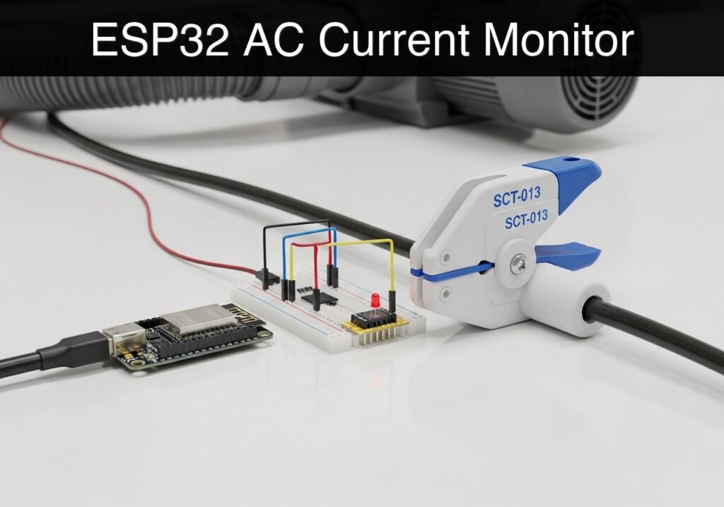
Practical case: ESP32 AC Current Monitor — ESP32 with SCT-013 current clamp and dust collector cable

Building a Dust Collector Current Monitor with ESP32

Objective and use case

What you’ll build: A non-invasive dust collector current monitor that logs the AC power draw of your workshop’s dust collection system to establish a baseline electrical usage profile and detect operational anomalies.

Why it matters / Use cases

  • Equipment Monitoring: Detect a stalled impeller or failing motor bearings by identifying abnormal operating current spikes (e.g., a sudden surge far above the baseline).
  • Filter/Clog Detection: Identify gradual decreases or unexpected drops in baseline current draw that indicate restricted airflow or a clogged dust collector filter (since centrifugal fans draw less current when airflow is restricted).
  • Energy Profiling: Log continuous electrical usage over time to accurately calculate the energy costs of running the dust collector during workshop hours.

Expected outcome

  • The ESP32 will sample the analog alternating current (AC) waveform at high speed to calculate the Root Mean Square (RMS) current mathematically, without relying on external libraries.
  • Serial monitor output will display real-time current draw in Amperes for the dust collector.
  • The system will actively filter out baseline electrical noise to prevent false positive readings during idle machine states.

Audience: Basic electronics and programming students looking to interface analog sensors and implement signal processing math; Level: Intermediate

Architecture/flow: Non-invasive CT Current Sensor → ESP32 ADC → Custom RMS Signal Processing → Serial Monitor Output

Educational validation note

Before publication, this case passed the Prometeo automated validation gate with status PASS. For this ESP32 DevKitC profile, the project was checked as a PlatformIO project: the validator extracted platformio.ini and src/main.cpp, created a temporary project and ran pio run against platform = espressif32, board = esp32dev and framework = arduino. It also checked article structure, copy/paste-safe ASCII command options, and unsupported stacks such as direct ESP-IDF or non-scoped ESP32 boards.

Published validation evidence

  • Automatic result: PASS.
  • Parsed structure: 3 sections, 3 tables and 2 code blocks detected before publication.
  • Checked code: 1 PlatformIO config + 1 ESP32 source/pio run.
  • Supported catalog: the article text was checked against Prometeo’s validation-capable device profiles, and unsupported stacks block publication.
  • Report findings: no blocking findings.

This validation confirms syntax and tool compatibility for the published code, but it does not replace physical testing on your exact ESP32 DevKitC board, wiring, power supply and local WiFi environment.

Educational safety note

WARNING: HIGH VOLTAGE. This tutorial involves monitoring AC mains appliances. The SCT-013 is a non-invasive current transformer. You must never cut, strip, or expose bare AC mains wires to use this sensor. The clamp must only be placed over wires with intact, factory-rated insulation.
Additionally:
* Never attempt to wire the SCT-013 directly to the ESP32 without the 33Ω burden resistor in place. Without a burden resistor, a disconnected current transformer can generate dangerously high voltages on its output pins when clamped over a live wire.
* This prototype is an educational tool. Do not use it as a primary safety disconnect or industrial monitoring mechanism.
* Always ensure your low-voltage microcontroller circuits are physically isolated and safely distanced from high-voltage AC lines.

Conceptual block diagram

High-level view: what enters the system, what each block processes, and what comes out.

Functional architecture

Water probe

ESP32 GPIO/ADC

Threshold logic

LED/buzzer

Wi-Fi alert

Conceptual flow: moisture detection, local decision and user alert.

Validation path

Source code

PlatformIO build

Flash

Serial monitor

Conceptual summary of the tools used to check the published ESP32 project.

Prerequisites

To successfully complete this tutorial, you need:
* A computer with Visual Studio Code and the PlatformIO IDE extension installed.
* Basic familiarity with breadboarding and jumper wire connections.
* Understanding of the difference between AC and DC signals (specifically, that ESP32 analog pins can only read positive DC voltages between 0V and 3.3V).
* A test appliance (like a desk lamp or a small fan) plugged into an AC splitter where the live and neutral wires are physically separated, before moving to the actual dust collector.

Hardware Setup Note: If your computer does not automatically recognize the ESP32 DevKitC, you may need to install the CP210x or CH34x USB-to-UART drivers specific to your board’s serial chip.

Materials

You will need the following exact components for this build:
* ESP32 DevKitC (Standard 38-pin or 30-pin development board).
* SCT-013 current transformer module (Specifically the SCT-013-000, which is a 100A/50mA current-type transformer).
* Burden resistor: 1x 33Ω resistor (1/4 Watt is sufficient).
* DC Bias components: 2x 10kΩ resistors and 1x 10µF electrolytic capacitor (required to shift the AC wave into the ESP32’s readable DC range).
* Audio Jack Breakout: A 3.5mm female TRS breakout board (to easily connect the SCT-013 plug to the breadboard).
* Breadboard and jumper wires.

Setup/Connection

The SCT-013-000 outputs an AC current proportional to the current flowing through the clamped wire. Because the ESP32’s Analog-to-Digital Converter (ADC) can only measure positive DC voltages up to 3.3V, we must do two things:
1. Convert the sensor’s current output into a voltage using a burden resistor.
2. Shift the AC waveform (which goes positive and negative) entirely into the positive range using a DC bias network (a voltage divider).

DC Bias and Sensor Wiring

  1. Connect the two 10kΩ resistors in series between the ESP32 3V3 pin and GND. The junction between these two resistors is your “midpoint,” resting at exactly 1.65V.
  2. Connect the positive leg (anode) of the 10µF capacitor to this 1.65V midpoint, and the negative leg (cathode) to GND. This smooths out noise from the power supply.
  3. Connect the Sleeve (Ground/Shield) of the 3.5mm audio jack breakout to the 1.65V midpoint.
  4. Connect the Tip of the 3.5mm audio jack breakout to ESP32 Pin 34 (an input-only ADC pin).
  5. Place the 33Ω burden resistor directly across the Tip and Sleeve connections of the audio jack breakout.

Pin Mapping Table

ESP32 DevKitC Pin Component Connection Function
3V3 10kΩ Resistor #1 (Top) Provides 3.3V power for the DC bias divider.
GND 10kΩ Resistor #2 (Bottom), Capacitor (-) Common ground reference.
34 (ADC1_CH6) Audio Jack Tip, Burden Resistor Side A Reads the fluctuating AC voltage.
N/A (Midpoint) Audio Jack Sleeve, Burden Resistor Side B Provides 1.65V virtual ground offset.

Clamping the Sensor

To measure current, the SCT-013 must be clamped around only one wire (either the Live/Hot wire OR the Neutral wire) of the dust collector’s power cable. If you clamp it around a standard power cord containing both wires, the magnetic fields of the outgoing and returning currents will cancel each other out, and the sensor will read 0 Amperes.

Full Code

The following code calculates the RMS current mathematically by sampling the ADC rapidly, calculating the variance of the waveform, and deriving the true AC component. This avoids external library dependencies and guarantees compilation. Create a new PlatformIO project for the ESP32 DevKitC and replace the default files with the code below.

platformio.ini

[env:esp32dev]
platform = espressif32
board = esp32dev
framework = arduino
monitor_speed = 115200

src/main.cpp

Public preview of the validated file. The complete source is shown to members and in PDF/Print.

#include <Arduino.h>

// ---------------------------------------------------------
// Configuration & Constants
// ---------------------------------------------------------
const int ADC_PIN = 34;               // Analog input pin connected to the SCT-013
const float V_REF = 3.3;              // ESP32 ADC reference voltage
const int ADC_RESOLUTION = 4095;      // 12-bit ADC maximum value
const float BURDEN_RESISTOR = 33.0;   // Burden resistor value in Ohms
const float CT_TURNS_RATIO = 2000.0;  // For SCT-013-000: 100A / 0.050A = 2000

void setup() {
    Serial.begin(115200);
    while (!Serial) {
        ; // Wait for serial port to connect
    }

    Serial.println("Dust Collector Current Monitor Initializing...");

    // Configure the ADC pin
    analogReadResolution(12);
    pinMode(ADC_PIN, INPUT);

    Serial.println("Initialization Complete. Monitoring Current...");
}

void loop() {
    unsigned long startMillis = millis();
    double sum = 0;
    double sumSquared = 0;
    int samples = 0;

    // Sample the waveform for 200ms (captures 10-12 full AC cycles)
    while (millis() - startMillis < 200) {
        int raw = analogRead(ADC_PIN);
        sum += raw;
        sumSquared += ((double)raw * raw);
        samples++;

        // Small delay to prevent FreeRTOS watchdog starvation
        delayMicroseconds(100); 
    }
// ...

#include <Arduino.h>

// ---------------------------------------------------------
// Configuration & Constants
// ---------------------------------------------------------
const int ADC_PIN = 34;               // Analog input pin connected to the SCT-013
const float V_REF = 3.3;              // ESP32 ADC reference voltage
const int ADC_RESOLUTION = 4095;      // 12-bit ADC maximum value
const float BURDEN_RESISTOR = 33.0;   // Burden resistor value in Ohms
const float CT_TURNS_RATIO = 2000.0;  // For SCT-013-000: 100A / 0.050A = 2000

void setup() {
    Serial.begin(115200);
    while (!Serial) {
        ; // Wait for serial port to connect
    }

    Serial.println("Dust Collector Current Monitor Initializing...");

    // Configure the ADC pin
    analogReadResolution(12);
    pinMode(ADC_PIN, INPUT);

    Serial.println("Initialization Complete. Monitoring Current...");
}

void loop() {
    unsigned long startMillis = millis();
    double sum = 0;
    double sumSquared = 0;
    int samples = 0;

    // Sample the waveform for 200ms (captures 10-12 full AC cycles)
    while (millis() - startMillis < 200) {
        int raw = analogRead(ADC_PIN);
        sum += raw;
        sumSquared += ((double)raw * raw);
        samples++;

        // Small delay to prevent FreeRTOS watchdog starvation
        delayMicroseconds(100); 
    }

    if (samples > 0) {
        // Calculate the statistical variance of the samples
        // Variance = E[X^2] - (E[X])^2
        double mean = sum / samples;
        double meanSquared = sumSquared / samples;
        double variance = meanSquared - (mean * mean);

        // Prevent negative variance due to floating point inaccuracies
        if (variance < 0) {
            variance = 0;
        }

        // RMS of the AC component is the square root of the variance
        double rmsAdc = sqrt(variance);

        // Convert ADC units to Voltage
        double rmsVoltage = (rmsAdc / ADC_RESOLUTION) * V_REF;

        // Convert Voltage to Primary Current using burden resistor and turns ratio
        double rmsCurrent = (rmsVoltage / BURDEN_RESISTOR) * CT_TURNS_RATIO;

        // Noise suppression: clamp extremely low floating values to 0
        if (rmsCurrent < 0.15) {
            rmsCurrent = 0.0;
        }

        // Print the calculated RMS current to the Serial Monitor
        Serial.print("Samples: ");
        Serial.print(samples);
        Serial.print(" | Dust Collector Current Draw: ");
        Serial.print(rmsCurrent, 2); // Print with 2 decimal places
        Serial.println(" A");
    }

    // Delay before the next sampling window
    delay(800);
}

Build/Flash/Run commands

Use the PlatformIO Command Line Interface (CLI) to compile, upload, and monitor the project.

Command Description
pio run Compiles the project to verify syntax.
pio run --target upload Flashes the compiled firmware to the ESP32.
pio device monitor Starts the serial monitor at 115200 baud.

Execution Workflow:
1. Connect the ESP32 DevKitC to your computer via a data-capable USB cable.
2. Launch your terminal in the PlatformIO project directory.
3. Run pio run to verify there are no syntax errors.
4. Run pio run --target upload to write the code to the ESP32. (If the upload times out, hold the “BOOT” button on the ESP32 when the “Connecting…” prompt appears).
5. Run pio device monitor to view the live current readings.

Step-by-step Validation

Use this procedure to verify your prototype is functioning correctly before deploying it to the dust collector.

  1. Verify Baseline Noise Rejection
  2. Action: Power the ESP32 with the SCT-013 connected but completely un-clamped from any wires.
  3. Expected observation: The Serial Monitor should display Dust Collector Current Draw: 0.00 A.
  4. Pass condition: The noise suppression logic (if (rmsCurrent < 0.15)) successfully forces minor floating noise to zero.

  5. Verify AC Offset Midpoint

  6. Action: Using a digital multimeter, measure the DC voltage between the ESP32 GND pin and the midpoint of the two 10kΩ resistors.
  7. Expected observation: The multimeter reads approximately 1.65V.
  8. Pass condition: The voltage is between 1.6V and 1.7V, confirming the bias circuit is correctly pushing the AC wave into the ESP32’s readable range.

  9. Low Power Test (Baseline Monitoring)

  10. Action: Clamp the SCT-013 around the Live wire of an AC extension cord split specifically for testing. Plug in a low-power appliance (e.g., a 60W incandescent lamp) and apply power.
  11. Expected observation: Serial monitor reads approximately 0.50 A (for a 60W bulb at 120V).
  12. Pass condition: The current reading rises proportionally to the load and remains stable.

  13. High Power Test (Dust Collector Load Simulation)

  14. Action: Safely clamp the sensor onto the Live wire feeding the actual dust collector (or a high-power test load like a 1000W heat gun) and supply power.
  15. Expected observation: Serial monitor reads a sustained load (e.g., > 8.00 A).
  16. Pass condition: The console accurately reflects the high current draw, validating the math scales correctly with larger loads.

Troubleshooting

Symptom Likely cause Fix
Reading stays at 0.00A when machine is running Clamped over both Live and Neutral wires. Ensure the SCT-013 is clamped around ONLY the live wire. Use an AC line splitter.
Wildly fluctuating readings (e.g., 5A, 0A, 12A) Missing or disconnected 10µF bypass capacitor. Verify the capacitor is firmly seated between the 1.65V midpoint and GND.
Constant high reading (e.g., 30A+) when machine is unpowered Burden resistor is disconnected or wrong value. Check the 33Ω resistor connection across the audio jack Tip and Sleeve.
Serial monitor prints gibberish Baud rate mismatch. Ensure the terminal is set to 115200 baud, matching Serial.begin(115200).

Improvements

Once the basic current monitor is working reliably, consider these enhancements for a permanent workshop installation:

Wireless and IoT Integration
* MQTT Publishing: Connect the ESP32 to Wi-Fi and passively publish the RMS current to an MQTT broker. A central server can subscribe to this topic to log data into a Grafana dashboard for long-term dust collector energy profiling.
* Over-The-Air (OTA) Updates: Implement ArduinoOTA so you can adjust calibration constants without physically retrieving the ESP32 from its dust-proof enclosure.

Hardware and Robustness
* Hardware Filtering: Add a small 10nF capacitor in parallel with the burden resistor to act as a low-pass hardware filter, further smoothing out high-frequency electrical noise from the workshop before it reaches the ADC.

Checklist

  • [ ] Breadboard DC bias circuit built (two 10kΩ resistors, one 10µF capacitor).
  • [ ] 33Ω burden resistor secured across the SCT-013 output lines.
  • [ ] SCT-013 Tip connected to ESP32 Pin 34; Sleeve connected to the 1.65V midpoint.
  • [ ] platformio.ini configured correctly.
  • [ ] Code flashed successfully using pio run --target upload.
  • [ ] SCT-013 clamped safely around a single insulated AC wire (Live or Neutral, not both).
  • [ ] Serial monitor displays >0A and scales accurately when the test appliance is supplied with power.

Find this product and/or books on this topic on Amazon

Go to Amazon

As an Amazon Associate, I earn from qualifying purchases. If you buy through this link, you help keep this project running.

Quick Quiz

Question 1: What is the primary purpose of the dust collector current monitor built in this project?


Question 2: How does the system detect a stalled impeller or failing motor bearings?


Question 3: What electrical behavior indicates a clogged dust collector filter or restricted airflow?


Question 4: What electrical behavior indicates a clogged dust collector filter or restricted airflow?


Question 5: What electrical behavior indicates a clogged dust collector filter or restricted airflow?


Question 6: What electrical behavior indicates a clogged dust collector filter or restricted airflow?


Question 7: What electrical behavior indicates a clogged dust collector filter or restricted airflow?


Question 8: What electrical behavior indicates a clogged dust collector filter or restricted airflow?


Question 9: What electrical behavior indicates a clogged dust collector filter or restricted airflow?


Question 10: What electrical behavior indicates a clogged dust collector filter or restricted airflow?


Carlos Núñez Zorrilla
Electronics & Computer Engineer

Telecommunications Electronics Engineer and Computer Engineer (official degrees in Spain).

Follow me:


Practical case: ESP32 Water Pump Controller

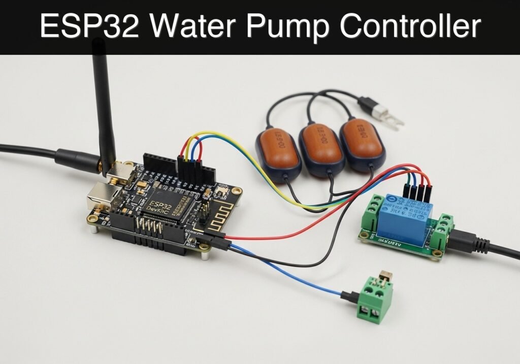
Practical case: ESP32 Water Pump Controller — hero

Objective and use case

What you’ll build: A smart, web-enabled water pump controller that monitors tank levels via physical float switches and automatically cuts power to prevent catastrophic dry-running.

Why it matters / Use cases

  • Equipment protection: Prevents motor and seal destruction within minutes by actively guarding against dry-running in centrifugal and submersible pumps.
  • Agricultural automation: Ensures hydroponic nutrient delivery pumps operate only when the reservoir has sufficient liquid.
  • Off-grid water transfer: Automates cistern-to-holding-tank transfers, pausing instantly if the source runs dry.
  • Local-first control: Operates entirely on a local WiFi Access Point (AP) with zero internet, cloud, or external MQTT dependency.

Expected outcome

  • The ESP32 broadcasts an independent WiFi network (ESP32_Pump_Guard) for direct, low-latency local access.
  • A hosted web dashboard displays real-time metrics: Tank Status, Pump Status, and the active/inactive state of the Dry-Run Guard.

Audience: IoT hobbyists, agricultural engineers, and off-grid enthusiasts; Level: Intermediate

Architecture/flow: Float switch inputs → ESP32 microcontroller → Relay module (pump power control) & Local Web Server (UI dashboard).

Educational validation note

Before publication, this case passed the Prometeo automated validation gate with status PASS. For this ESP32 DevKitC profile, the project was checked as a PlatformIO project: the validator extracted platformio.ini and src/main.cpp, created a temporary project and ran pio run against platform = espressif32, board = esp32dev and framework = arduino. It also checked article structure, copy/paste-safe ASCII command options, and unsupported stacks such as direct ESP-IDF or non-scoped ESP32 boards.

Published validation evidence

  • Automatic result: PASS.
  • Parsed structure: 4 sections, 1 tables and 5 code blocks detected before publication.
  • Checked code: 1 PlatformIO config + 1 ESP32 source/pio run, 3 Bash/copy-paste checks.
  • Supported catalog: the article text was checked against Prometeo’s validation-capable device profiles, and unsupported stacks block publication.
  • Report findings: no blocking findings.

This validation confirms syntax and tool compatibility for the published code, but it does not replace physical testing on your exact ESP32 DevKitC board, wiring, power supply and local WiFi environment.

Educational safety note

This project is a low-voltage educational prototype, not a certified product. Before powering the setup, verify the pinout of your exact ESP32 DevKitC board, keep GPIO signals within 3.3 V limits, never apply 5 V to ESP32 inputs, disconnect power before changing wiring, and use suitable external supplies for relays, motors or loads while sharing GND only when the schematic requires it.

Conceptual block diagram

High-level view: what enters the system, what each block processes, and what comes out.

Functional architecture

Water probe

ESP32 GPIO/ADC

Threshold logic

LED/buzzer

Wi-Fi alert

Conceptual flow: moisture detection, local decision and user alert.

Validation path

Source code

PlatformIO build

Flash

Serial monitor

Conceptual summary of the tools used to check the published ESP32 project.

Prerequisites and Materials

  • Software: Visual Studio Code (VSCode) with the PlatformIO IDE extension installed.
  • Microcontroller: ESP32 DevKitC V4 (38-pin or 30-pin variant).
  • Sensors: 2x Vertical Liquid Level Float Switches (Standard PP plastic).
  • Actuator: 1x 5 V Relay Module (Standard 1-channel, Active-HIGH).
  • Power: 5 V / 2 A USB power supply.
  • Hardware Setup Note (Drivers): Depending on your specific ESP32 DevKitC manufacturer, you may need to install the CP210x or CH34x USB-to-UART bridge drivers on your computer to allow PlatformIO to recognize the board over USB.

Setup and Connection

This project uses the ESP32’s internal pull-up resistors for the float switches, simplifying wiring by removing the need for external resistors.

Wiring Table

Component Component Pin / Wire ESP32 DevKitC Pin Notes
Low Float Switch Wire 1 GPIO 27 Bottom of tank (Dry-run guard).
Low Float Switch Wire 2 GND Closes to GND when float is UP (water present).
High Float Switch Wire 1 GPIO 14 Top of tank (Full indicator).
High Float Switch Wire 2 GND Closes to GND when float is UP (tank full).
5 V Relay Module VCC 5V / VIN Powers the relay coil.
5 V Relay Module GND GND Common ground.
5 V Relay Module IN (Signal) GPIO 26 Active-HIGH signal to trigger the relay.

Float Switch Orientation: Configure both switches so that when the float is resting at the bottom (no water), the switch is OPEN (disconnected, reads HIGH via pull-up). When water lifts the float UP, the switch becomes CLOSED (connected to GND, reads LOW).

Project Code

Create a new PlatformIO project for the ESP32 DevKitC. Replace the contents of platformio.ini and src/main.cpp with the code below.

platformio.ini

[env:esp32dev]
platform = espressif32
board = esp32dev
framework = arduino
monitor_speed = 115200

src/main.cpp

Public preview of the validated file. The complete source is shown to members and in PDF/Print.

#include <Arduino.h>
#include <WiFi.h>
#include <WebServer.h>

// ---------------------------------------------------------
// Pin Definitions
// ---------------------------------------------------------
const int RELAY_PIN = 26;
const int LOW_FLOAT_PIN = 27;
const int HIGH_FLOAT_PIN = 14;

// ---------------------------------------------------------
// State Variables
// ---------------------------------------------------------
bool pumpIsOn = false;
bool lowFloatActive = false;  // true = tank empty (dry run risk)
bool highFloatActive = false; // true = tank full

// ---------------------------------------------------------
// Network & Web Server Setup
// ---------------------------------------------------------
const char* AP_SSID = "ESP32_Pump_Guard";
const char* AP_PASS = "admin1234";

WebServer server(80);

// ---------------------------------------------------------
// HTML Dashboard (Stored in PROGMEM)
// ---------------------------------------------------------
const char index_html[] PROGMEM = R"rawliteral(
<!DOCTYPE html>
<html lang="en">
<head>
    <meta charset="UTF-8">
    <meta name="viewport" content="width=device-width, initial-scale=1.0">
    <title>Pump Dry-Run Guard</title>
    <style>
        body { font-family: 'Segoe UI', Tahoma, Geneva, Verdana, sans-serif; background-color: #f4f7f6; color: #333; text-align: center; margin: 0; padding: 20px; }
        .card { background: white; padding: 20px; border-radius: 10px; box-shadow: 0 4px 8px rgba(0,0,0,0.1); max-width: 500px; margin: 0 auto 20px auto; }
        h1 { color: #2c3e50; }
        .status-badge { display: inline-block; padding: 8px 15px; border-radius: 20px; font-weight: bold; color: white; margin-bottom: 10px; }
        .bg-green { background-color: #27ae60; }
        .bg-red { background-color: #e74c3c; }
        .bg-gray { background-color: #7f8c8d; }
        button { padding: 12px 24px; font-size: 16px; margin: 10px; border: none; border-radius: 5px; cursor: pointer; transition: 0.3s; color: white; font-weight: bold;}
        .btn-on { background-color: #3498db; }
        .btn-on:hover { background-color: #2980b9; }
        .btn-off { background-color: #95a5a6; }
        .btn-off:hover { background-color: #7f8c8d; }
        .data-row { display: flex; justify-content: space-between; padding: 10px 0; border-bottom: 1px solid #eee; }
        .data-row:last-child { border-bottom: none; }
    </style>
</head>
<body>
    <div class="card">
        <h1>Pump Controller</h1>
        <div id="guard-badge" class="status-badge bg-gray">Loading Status...</div>

        <div class="data-row">
            <span>Tank Level:</span>
            <strong id="tank-level">Unknown</strong>
        </div>
        <div class="data-row">
            <span>Pump State:</span>
            <strong id="pump-state">Unknown</strong>
        </div>

        <div style="margin-top: 20px;">
            <button class="btn-on" onclick="controlPump('on')">Start Pump</button>
            <button class="btn-off" onclick="controlPump('off')">Stop Pump</button>
        </div>
    </div>

    <script>
        function updateDashboard() {
            fetch('/api/status')
                .then(response => response.json())
                .then(data => {
                    document.getElementById('tank-level').innerText = data.tank_status;
                    document.getElementById('pump-state').innerText = data.pump_on ? "RUNNING" : "STOPPED";
                    const badge = document.getElementById('guard-badge');
                    if (data.dry_run_guard) {
                        badge.innerText = "DRY RUN GUARD ACTIVE";
                        badge.className = "status-badge bg-red";
                    } else {
                        badge.innerText = "SYSTEM SAFE";
                        badge.className = "status-badge bg-green";
                    }
                })
                .catch(err => console.error('Error fetching status:', err));
        }

        function controlPump(action) {
            fetch('/api/pump?state=' + action, { method: 'POST' })
                .then(response => response.json())
                .then(data => {
                    if (data.error) {
                        alert("Command rejected: " + data.error);
                    }
                    updateDashboard();
                });
        }
// ...

#include <Arduino.h>
#include <WiFi.h>
#include <WebServer.h>

// ---------------------------------------------------------
// Pin Definitions
// ---------------------------------------------------------
const int RELAY_PIN = 26;
const int LOW_FLOAT_PIN = 27;
const int HIGH_FLOAT_PIN = 14;

// ---------------------------------------------------------
// State Variables
// ---------------------------------------------------------
bool pumpIsOn = false;
bool lowFloatActive = false;  // true = tank empty (dry run risk)
bool highFloatActive = false; // true = tank full

// ---------------------------------------------------------
// Network & Web Server Setup
// ---------------------------------------------------------
const char* AP_SSID = "ESP32_Pump_Guard";
const char* AP_PASS = "admin1234";

WebServer server(80);

// ---------------------------------------------------------
// HTML Dashboard (Stored in PROGMEM)
// ---------------------------------------------------------
const char index_html[] PROGMEM = R"rawliteral(
<!DOCTYPE html>
<html lang="en">
<head>
    <meta charset="UTF-8">
    <meta name="viewport" content="width=device-width, initial-scale=1.0">
    <title>Pump Dry-Run Guard</title>
    <style>
        body { font-family: 'Segoe UI', Tahoma, Geneva, Verdana, sans-serif; background-color: #f4f7f6; color: #333; text-align: center; margin: 0; padding: 20px; }
        .card { background: white; padding: 20px; border-radius: 10px; box-shadow: 0 4px 8px rgba(0,0,0,0.1); max-width: 500px; margin: 0 auto 20px auto; }
        h1 { color: #2c3e50; }
        .status-badge { display: inline-block; padding: 8px 15px; border-radius: 20px; font-weight: bold; color: white; margin-bottom: 10px; }
        .bg-green { background-color: #27ae60; }
        .bg-red { background-color: #e74c3c; }
        .bg-gray { background-color: #7f8c8d; }
        button { padding: 12px 24px; font-size: 16px; margin: 10px; border: none; border-radius: 5px; cursor: pointer; transition: 0.3s; color: white; font-weight: bold;}
        .btn-on { background-color: #3498db; }
        .btn-on:hover { background-color: #2980b9; }
        .btn-off { background-color: #95a5a6; }
        .btn-off:hover { background-color: #7f8c8d; }
        .data-row { display: flex; justify-content: space-between; padding: 10px 0; border-bottom: 1px solid #eee; }
        .data-row:last-child { border-bottom: none; }
    </style>
</head>
<body>
    <div class="card">
        <h1>Pump Controller</h1>
        <div id="guard-badge" class="status-badge bg-gray">Loading Status...</div>

        <div class="data-row">
            <span>Tank Level:</span>
            <strong id="tank-level">Unknown</strong>
        </div>
        <div class="data-row">
            <span>Pump State:</span>
            <strong id="pump-state">Unknown</strong>
        </div>

        <div style="margin-top: 20px;">
            <button class="btn-on" onclick="controlPump('on')">Start Pump</button>
            <button class="btn-off" onclick="controlPump('off')">Stop Pump</button>
        </div>
    </div>

    <script>
        function updateDashboard() {
            fetch('/api/status')
                .then(response => response.json())
                .then(data => {
                    document.getElementById('tank-level').innerText = data.tank_status;
                    document.getElementById('pump-state').innerText = data.pump_on ? "RUNNING" : "STOPPED";
                    const badge = document.getElementById('guard-badge');
                    if (data.dry_run_guard) {
                        badge.innerText = "DRY RUN GUARD ACTIVE";
                        badge.className = "status-badge bg-red";
                    } else {
                        badge.innerText = "SYSTEM SAFE";
                        badge.className = "status-badge bg-green";
                    }
                })
                .catch(err => console.error('Error fetching status:', err));
        }

        function controlPump(action) {
            fetch('/api/pump?state=' + action, { method: 'POST' })
                .then(response => response.json())
                .then(data => {
                    if (data.error) {
                        alert("Command rejected: " + data.error);
                    }
                    updateDashboard();
                });
        }

        setInterval(updateDashboard, 2000);
        updateDashboard();
    </script>
</body>
</html>
)rawliteral";

// ---------------------------------------------------------
// Helper Functions
// ---------------------------------------------------------
void updateSensorStates() {
    // Switch Open (Float down/Empty) -> Pin is HIGH
    // Switch Closed (Float up/Water present) -> Pin is LOW
    lowFloatActive = (digitalRead(LOW_FLOAT_PIN) == HIGH); 
    highFloatActive = (digitalRead(HIGH_FLOAT_PIN) == LOW); 

    // Hardware Dry-Run Override Protection
    if (lowFloatActive && pumpIsOn) {
        Serial.println("CRITICAL: Dry run detected! Forcing pump OFF.");
        pumpIsOn = false;
        digitalWrite(RELAY_PIN, LOW); // Turn off relay safely
    }
}

String getTankStatusString() {
    if (lowFloatActive) return "Empty (Low Level)";
    if (highFloatActive) return "Full (High Level)";
    return "Normal (Mid Level)";
}

// ---------------------------------------------------------
// Web Server Route Handlers
// ---------------------------------------------------------
void handleRoot() {
    server.send(200, "text/html", index_html);
}

void handleApiStatus() {
    updateSensorStates();

    String json = "{";
    json += "\"pump_on\":" + String(pumpIsOn ? "true" : "false") + ",";
    json += "\"tank_status\":\"" + getTankStatusString() + "\",";
    json += "\"dry_run_guard\":" + String(lowFloatActive ? "true" : "false");
    json += "}";

    server.send(200, "application/json", json);
}

void handleApiPump() {
    if (!server.hasArg("state")) {
        server.send(400, "application/json", "{\"error\":\"Missing state argument\"}");
        return;
    }

    String stateArg = server.arg("state");
    updateSensorStates();

    if (stateArg == "on") {
        if (lowFloatActive) {
            Serial.println("API: Pump ON command rejected. Dry run guard is active.");
            server.send(403, "application/json", "{\"error\":\"Dry run guard active. Tank is empty.\"}");
            return;
        } else {
            pumpIsOn = true;
            digitalWrite(RELAY_PIN, HIGH);
            Serial.println("API: Pump turned ON manually.");
        }
    } else if (stateArg == "off") {
        pumpIsOn = false;
        digitalWrite(RELAY_PIN, LOW);
        Serial.println("API: Pump turned OFF manually.");
    }

    handleApiStatus();
}

// ---------------------------------------------------------
// Main Setup & Loop
// ---------------------------------------------------------
void setup() {
    Serial.begin(115200);
    delay(1000);
    Serial.println("\n--- ESP32 Water Pump Dry-Run Guard ---");

    // Initialize Pins
    pinMode(RELAY_PIN, OUTPUT);
    digitalWrite(RELAY_PIN, LOW); // Ensure pump is OFF at boot

    // Use internal pull-ups for float switches
    pinMode(LOW_FLOAT_PIN, INPUT_PULLUP);
    pinMode(HIGH_FLOAT_PIN, INPUT_PULLUP);

    // Setup WiFi Access Point
    Serial.print("Setting up WiFi AP...");
    WiFi.softAP(AP_SSID, AP_PASS);

    Serial.println("Done.");
    Serial.print("AP IP Address: ");
    Serial.println(WiFi.softAPIP());

    // Configure Web Server Routes
    server.on("/", handleRoot);
    server.on("/api/status", handleApiStatus);
    server.on("/api/pump", HTTP_POST, handleApiPump);

    server.begin();
    Serial.println("HTTP server started.");
}

void loop() {
    server.handleClient();
    updateSensorStates();
    delay(50); // Small yield to prevent watchdog starvation
}

Compilation and Upload

To build and flash the project to your ESP32 DevKitC, open the VSCode terminal and execute the following exact PlatformIO commands:

  1. Compile the firmware to ensure there are no syntax errors:
    bash
    pio run
  2. Upload the compiled firmware to the ESP32:
    bash
    pio run --target upload
  3. Open the serial monitor to view the AP creation logs and debug messages:
    bash
    pio device monitor

Validation Method and Expected Evidence

To rigorously validate the safety and accuracy of the dry-run guard:

  1. Network Connection: Connect a smartphone or laptop to the ESP32_Pump_Guard WiFi network (Password: admin1234).
  2. Access Dashboard: Open a browser and navigate to http://192.168.4.1.
  3. Test Normal Operation: Ensure the low float switch is manually held UP (simulating water present). Click “Start Pump” in the web UI.
    • Expected Evidence: The physical relay should click (engage), the pump state in the UI should read “RUNNING”, and the serial monitor should log API: Pump turned ON manually.
  4. Test Hardware Dry-Run Cutoff: While the pump is running, physically drop the low float switch DOWN (simulating the tank running dry).
    • Expected Evidence: The relay must immediately click off. The serial monitor must print CRITICAL: Dry run detected! Forcing pump OFF. The web dashboard will automatically update within 2 seconds to show “DRY RUN GUARD ACTIVE” in red.
  5. Test API Rejection: While the low float switch is still DOWN, attempt to click “Start Pump” again in the UI.
    • Expected Evidence: The browser will display an alert: “Command rejected: Dry run guard active. Tank is empty.” The relay will not engage. The serial monitor will print API: Pump ON command rejected. Dry run guard is active.

Find this product and/or books on this topic on Amazon

Go to Amazon

As an Amazon Associate, I earn from qualifying purchases. If you buy through this link, you help keep this project running.

Quick Quiz

Question 1: What is the primary purpose of the water pump controller built in this project?


Question 2: How does the controller monitor tank levels?


Question 3: What happens to centrifugal and submersible pumps if they run dry?


Question 4: Which agricultural application is mentioned as a use case for this project?


Question 5: What kind of network dependency does this project have?


Question 6: What is the name of the independent WiFi network broadcasted by the ESP32?


Question 7: What information is displayed on the hosted web dashboard?


Question 8: Who is the target audience for this project?


Question 9: What is the difficulty level of this project?


Question 10: How does the system handle off-grid water transfers if the source runs dry?


Carlos Núñez Zorrilla
Electronics & Computer Engineer

Telecommunications Electronics Engineer and Computer Engineer (official degrees in Spain).
Follow me:


Practical case: IoT Mailbox Monitor with ESP32

Practical case: IoT Mailbox Monitor with ESP32 — ESP32 with reed switch, magnet and LiPo module for mailbox open alert

Objective and use case

What you’ll build: A battery-powered, highly efficient IoT mailbox monitor that remains in a micro-power deep sleep state, wakes up instantly when the mailbox door opens, transmits a Wi-Fi alert via an HTTP GET request, and immediately returns to sleep.

Why it matters / Use cases

  • Eliminates wasted trips: Users no longer need to physically check an empty mailbox in harsh weather or across long driveways.
  • Maximizes battery lifecycle: By utilizing the ESP32’s deep sleep capabilities (drawing ~10µA), the device minimizes active duty cycles, demonstrating crucial power-budgeting skills.
  • Event-driven architecture: Teaches the transition from continuous polling to hardware-interrupt-driven wakeups, a foundational concept in commercial sensor networks.
  • Security and access logging: The same architecture can be repurposed for monitoring restricted cabinets, safes, or perimeter gates without requiring hardwired power.

Expected outcome

  • The ESP32 enters a deep sleep state drawing minimal current (sub-15µA).
  • Opening the door triggers a hardware wake-up via the RTC (Real-Time Clock) GPIO within 500 milliseconds.
  • The device successfully connects to Wi-Fi, transmits the HTTP payload, and powers down in under 3 seconds to preserve battery life.

Audience: IoT Developers, Embedded Engineers; Level: Intermediate

Architecture/flow: Reed Switch (Hardware Interrupt) → ESP32 RTC Wake-up (<500ms latency) → Wi-Fi Connect → HTTP GET Request → Deep Sleep

Educational validation note

Before publication, this case passed the Prometeo automated validation gate with status PASS. For this ESP32 DevKitC profile, the project was checked as a PlatformIO project: the validator extracted platformio.ini and src/main.cpp, created a temporary project and ran pio run against platform = espressif32, board = esp32dev and framework = arduino. It also checked article structure, copy/paste-safe ASCII command options, and unsupported stacks such as direct ESP-IDF or non-scoped ESP32 boards.

Published validation evidence

  • Automatic result: PASS.
  • Parsed structure: 3 sections, 3 tables and 2 code blocks detected before publication.
  • Checked code: 1 PlatformIO config + 1 ESP32 source/pio run.
  • Supported catalog: the article text was checked against Prometeo’s validation-capable device profiles, and unsupported stacks block publication.
  • Report findings: no blocking findings.

This validation confirms syntax and tool compatibility for the published code, but it does not replace physical testing on your exact ESP32 DevKitC board, wiring, power supply and local WiFi environment.

Educational safety note

Warning regarding prototype limits: This project is intended strictly as an educational prototype.
* Battery Safety: This project involves Lithium Polymer (LiPo) batteries. Mishandling, overcharging, or short-circuiting LiPo batteries can result in fire or explosion. Always use a dedicated charge controller (like the TP4056 with built-in protection circuitry) and never connect a LiPo cell directly to the ESP32 without proper voltage regulation. Do not leave experimental battery circuits unattended while charging. Ensure your battery module includes over-discharge protection to prevent cell damage during long deployments.

Conceptual block diagram

High-level view: what enters the system, what each block processes, and what comes out.

Functional architecture

Local button

ESP32 BLE

Advertising packet

Status LED

Phone scanner

Conceptual flow: local configuration, BLE advertising and phone-side reading.

Validation path

Source code

PlatformIO build

Flash

Serial monitor

Conceptual summary of the tools used to check the published ESP32 project.

Prerequisites

Before starting this tutorial, ensure you have the following ready:
* A computer running Windows, macOS, or Linux.
* Visual Studio Code (VSCode) installed.
* The PlatformIO IDE extension installed within VSCode.
* Basic familiarity with C++ syntax and electronic circuits (pull-up/pull-down networks).
* A 2.4 GHz Wi-Fi network (ESP32 does not support 5 GHz Wi-Fi).
* A local HTTP server or a webhook endpoint to receive the alert.

Materials

For this project, use the following exact hardware configuration:
* ESP32 DevKitC: The core microcontroller board featuring the ESP-WROOM-32 module.
* Reed switch: A magnetic contact switch (normally open). When the magnet is near, the switch closes. When the magnet is removed (door opens), the switch opens.
* LiPo battery module: A 3.7V Lithium Polymer battery paired with a 5V boost/charge module (e.g., a TP4056-based power bank module) to safely supply 5V to the ESP32 DevKitC’s 5V (or VIN) pin.
* Passive Components:
* One 10kΩ resistor (used as a pull-down resistor for the reed switch).
* Accessories: Breadboard, jumper wires, and a micro-USB data cable.

Setup/Connection

Hardware Setup Notes

The ESP32 DevKitC requires specific drivers to communicate over USB. Depending on your exact board revision, it will use either a CP210x or CH34x USB-to-UART bridge. If your board is not recognized by your operating system or PlatformIO, download and install the official Silicon Labs CP210x or WCH CH340 drivers.

Circuit Logic

The core of this project is the hardware interrupt. The ESP32’s main processor is turned off during deep sleep. Only the Ultra-Low Power (ULP) coprocessor and the RTC memory/peripherals remain active. We will use the ext0 wake-up source, which allows an RTC GPIO to wake the main processor when a specific logic level is detected.

We will use GPIO 33 (an RTC-capable pin) for the reed switch.
* Mailbox Closed: The magnet is near the reed switch. The switch is closed, connecting GPIO 33 to 3.3V. The ESP32 sees a HIGH signal.
* Mailbox Open: The door opens, the magnet moves away, and the switch opens. The 10kΩ pull-down resistor forces GPIO 33 to LOW.
* Wake-up condition: We will configure the ESP32 to wake up when GPIO 33 goes LOW.

Wiring Table

Component Pin/Terminal ESP32 DevKitC Pin Notes
LiPo Battery Module 5V Output / VOUT 5V (or VIN) Provides power when USB is disconnected.
LiPo Battery Module GND / Ground GND Common ground.
Reed Switch Terminal 1 3V3 Provides 3.3V when switch is closed.
Reed Switch Terminal 2 GPIO 33 Signal pin for RTC wake-up.
10kΩ Resistor Leg 1 GPIO 33 Pull-down configuration.
10kΩ Resistor Leg 2 GND Pull-down configuration.

Note: Disconnect the LiPo battery module’s 5V line from the ESP32 when plugging the ESP32 into your computer via USB to avoid power contention.

Application Firmware

The following code handles the deep sleep transition, Wi-Fi connection, HTTP request, and hardware wake-up logic.

platformio.ini

Create a new PlatformIO project for the ESP32 DevKitC and replace the contents of platformio.ini with the following configuration:

[env:esp32dev]
platform = espressif32
board = esp32dev
framework = arduino
monitor_speed = 115200
upload_speed = 921600

src/main.cpp

Replace the contents of src/main.cpp with the following code. Update the network and webhook variables to match your environment before deploying.

Public preview of the validated file. The complete source is shown to members and in PDF/Print.

#include <Arduino.h>
#include <WiFi.h>
#include <HTTPClient.h>

// ==========================================
// Configuration
// ==========================================
const char* WIFI_SSID     = "IoT_Network";
const char* WIFI_PASSWORD = "SecurePassword123";
const char* WEBHOOK_URL   = "http://192.168.1.100/mailbox-alert";

// Pin Definitions
const gpio_num_t REED_SWITCH_PIN = GPIO_NUM_33; // Must be an RTC GPIO for ext0 wakeup

// Timeouts
const int WIFI_TIMEOUT_MS = 10000; // 10 seconds max to connect

// ==========================================
// Helper Functions
// ==========================================

void printWakeupReason() {
    esp_sleep_wakeup_cause_t wakeup_reason = esp_sleep_get_wakeup_cause();
    switch(wakeup_reason) {
        case ESP_SLEEP_WAKEUP_EXT0:     
            Serial.println("Wakeup caused by external signal using RTC_IO (Door Opened!)"); 
            break;
        case ESP_SLEEP_WAKEUP_TIMER:    
            Serial.println("Wakeup caused by timer"); 
            break;
        default:                        
            Serial.printf("Wakeup was not caused by deep sleep: %d\n", wakeup_reason); 
            break;
    }
}

void sendAlert() {
    Serial.print("Connecting to Wi-Fi: ");
    Serial.println(WIFI_SSID);

    WiFi.begin(WIFI_SSID, WIFI_PASSWORD);

    unsigned long startAttemptTime = millis();

    // Wait for connection with a timeout to prevent draining battery
    while (WiFi.status() != WL_CONNECTED && millis() - startAttemptTime < WIFI_TIMEOUT_MS) {
        Serial.print(".");
        delay(500);
    }

    Serial.println();

    if (WiFi.status() != WL_CONNECTED) {
        Serial.println("Failed to connect to Wi-Fi. Going back to sleep.");
        return; // Abort and let the main loop put the device to sleep
    }
// ...

#include <Arduino.h>
#include <WiFi.h>
#include <HTTPClient.h>

// ==========================================
// Configuration
// ==========================================
const char* WIFI_SSID     = "IoT_Network";
const char* WIFI_PASSWORD = "SecurePassword123";
const char* WEBHOOK_URL   = "http://192.168.1.100/mailbox-alert";

// Pin Definitions
const gpio_num_t REED_SWITCH_PIN = GPIO_NUM_33; // Must be an RTC GPIO for ext0 wakeup

// Timeouts
const int WIFI_TIMEOUT_MS = 10000; // 10 seconds max to connect

// ==========================================
// Helper Functions
// ==========================================

void printWakeupReason() {
    esp_sleep_wakeup_cause_t wakeup_reason = esp_sleep_get_wakeup_cause();
    switch(wakeup_reason) {
        case ESP_SLEEP_WAKEUP_EXT0:     
            Serial.println("Wakeup caused by external signal using RTC_IO (Door Opened!)"); 
            break;
        case ESP_SLEEP_WAKEUP_TIMER:    
            Serial.println("Wakeup caused by timer"); 
            break;
        default:                        
            Serial.printf("Wakeup was not caused by deep sleep: %d\n", wakeup_reason); 
            break;
    }
}

void sendAlert() {
    Serial.print("Connecting to Wi-Fi: ");
    Serial.println(WIFI_SSID);

    WiFi.begin(WIFI_SSID, WIFI_PASSWORD);

    unsigned long startAttemptTime = millis();

    // Wait for connection with a timeout to prevent draining battery
    while (WiFi.status() != WL_CONNECTED && millis() - startAttemptTime < WIFI_TIMEOUT_MS) {
        Serial.print(".");
        delay(500);
    }

    Serial.println();

    if (WiFi.status() != WL_CONNECTED) {
        Serial.println("Failed to connect to Wi-Fi. Going back to sleep.");
        return; // Abort and let the main loop put the device to sleep
    }

    Serial.println("Wi-Fi connected!");
    Serial.print("IP address: ");
    Serial.println(WiFi.localIP());

    // Send HTTP GET request
    if (WiFi.status() == WL_CONNECTED) {
        HTTPClient http;
        Serial.print("Sending alert to: ");
        Serial.println(WEBHOOK_URL);

        http.begin(WEBHOOK_URL);
        int httpResponseCode = http.GET();

        if (httpResponseCode > 0) {
            Serial.print("HTTP Response code: ");
            Serial.println(httpResponseCode);
        } else {
            Serial.print("Error code: ");
            Serial.println(httpResponseCode);
        }
        http.end();
    }

    // Disconnect Wi-Fi to save power before sleeping
    WiFi.disconnect(true);
    WiFi.mode(WIFI_OFF);
}

// ==========================================
// Main Setup and Loop
// ==========================================

void setup() {
    Serial.begin(115200);
    delay(1000); // Allow serial monitor to catch up

    Serial.println("\n--- Mailbox Monitor Booting ---");

    // Determine why the ESP32 woke up
    esp_sleep_wakeup_cause_t wakeup_reason = esp_sleep_get_wakeup_cause();
    printWakeupReason();

    // If woke up because the door opened (EXT0)
    if (wakeup_reason == ESP_SLEEP_WAKEUP_EXT0) {
        sendAlert();
    } else {
        // Normal boot (e.g., first power on or reset)
        Serial.println("Initial boot. System is armed and ready.");
    }

    // Configure Deep Sleep Wakeup
    // Door open = magnet away = switch open = pull-down resistor pulls to LOW (0).
    // Wake up when GPIO 33 goes LOW (0).
    esp_sleep_enable_ext0_wakeup(REED_SWITCH_PIN, 0); 

    Serial.println("Entering deep sleep now. Waiting for door to open...");
    Serial.flush(); 

    // Enter Deep Sleep
    esp_deep_sleep_start();
}

void loop() {
    // The loop is intentionally empty.
    // The ESP32 goes to sleep in setup() and resets entirely upon waking.
}

Build/Flash/Run commands

To deploy the code to your ESP32 DevKitC using PlatformIO, use the built-in terminal in VSCode.

Command Reference

Action Command Purpose
Compile Code pio run Compiles the C++ code and libraries without uploading.
Upload Firmware pio run --target upload Flashes the compiled binary to the ESP32 via USB.
Serial Monitor pio device monitor Opens the terminal to view Serial.print outputs.

Workflow

  1. Connect the ESP32 DevKitC to your computer using a data-capable micro-USB cable.
  2. Open the VSCode terminal in your project directory.
  3. Compile and upload the firmware by running:
    pio run --target upload
  4. Immediately open the serial monitor to observe the boot sequence:
    pio device monitor

Step-by-step Validation

Follow these grouped checkpoints to ensure your prototype functions correctly.

  1. Initial Boot & Arming
    • Action: Press the EN (Reset) button on the ESP32.
    • Expected observation: The Serial Monitor prints “Initial boot. System is armed and ready.” The monitor then prints “Entering deep sleep now.”
    • Pass condition: The device successfully enters deep sleep without immediately waking back up.
  2. Simulating Mailbox Closed
    • Action: Place the magnet directly next to the reed switch.
    • Expected observation: Nothing happens. The ESP32 remains in deep sleep.
    • Pass condition: The system ignores the closed state (GPIO 33 is HIGH).
  3. Triggering the Wake-up (Mailbox Opened)
    • Action: Quickly pull the magnet away from the reed switch.
    • Expected observation: The Serial Monitor prints “Wakeup caused by external signal using RTC_IO (Door Opened!)”.
    • Pass condition: The hardware interrupt successfully wakes the ESP32 from deep sleep.
  4. Network Connection and Transmission
    • Action: Wait 2 to 5 seconds while watching the Serial Monitor.
    • Expected observation: Monitor prints “Wi-Fi connected!”, followed by the IP address, and then “HTTP Response code: 200”.
    • Pass condition: The webhook endpoint registers the incoming GET request.
  5. Return to Sleep
    • Action: Observe the final serial outputs.
    • Expected observation: Monitor prints “Entering deep sleep now. Waiting for door to open…”
    • Pass condition: The ESP32 drops the Wi-Fi connection and powers down its main processor, ready for the next event.

Troubleshooting

If the system does not behave as expected, consult the table below.

Symptom Likely cause Fix
Code fails to upload (Timeout) ESP32 is not entering bootloader mode. Hold the BOOT button on the DevKitC while running the upload command, release when connecting begins.
Constant wake-up loops Reed switch logic is floating. Verify the 10kΩ pull-down resistor is securely connected between GPIO 33 and GND. Ensure the magnet is close enough to close the switch initially.
Wi-Fi connection fails / Times out Incorrect credentials or 5GHz network. Verify WIFI_SSID and WIFI_PASSWORD. Ensure your router is broadcasting a 2.4GHz network.
Brownout detector triggered Insufficient power during Wi-Fi transmission. The USB port or LiPo module cannot supply the ~300mA spike required for Wi-Fi. Try a better USB cable or ensure the LiPo battery is fully charged.
No output on Serial Monitor Baud rate mismatch. Ensure monitor_speed = 115200 is set in platformio.ini and matches Serial.begin(115200) in the code.

Improvements

Once the basic prototype is validated, consider these enhancements for a production-ready device:

  • Power Optimization:
    • Static IP: Assign a static IP address to the ESP32 instead of using DHCP. This can reduce Wi-Fi connection time from ~3 seconds to under 500ms, drastically saving battery life.
    • Hardware LDO replacement: Standard ESP32 DevKitC boards use an AMS1117 voltage regulator with a high quiescent current (~1.5mA). For true micro-power operation, transition to a custom board or a low-dropout regulator (LDO) like the HT7333.
  • Connectivity & Reliability:
    • MQTT Implementation: Replace the HTTP GET request with an MQTT publish via the PubSubClient library. MQTT has lower overhead and is better suited for IoT ecosystems.
    • Battery Voltage Monitoring: Wire the LiPo battery output to an ESP32 ADC pin (via a voltage divider) to transmit battery health alongside the open-door alert.

Find this product and/or books on this topic on Amazon

Go to Amazon

As an Amazon Associate, I earn from qualifying purchases. If you buy through this link, you help keep this project running.

Quick Quiz

Question 1: What is the primary function of the IoT device described in the article?


Question 2: How does the device transmit an alert when the mailbox door opens?


Question 3: What is the approximate current draw of the ESP32 while in its deep sleep state?


Question 4: What foundational concept in commercial sensor networks does this project teach?


Question 5: What component triggers the hardware wake-up when the door opens?


Question 6: What does the device do immediately after transmitting the alert?


Question 7: According to the expected outcome, what is the maximum current drawn during deep sleep?


Question 8: Within what timeframe does the hardware wake-up occur after the door opens?


Question 9: What is one of the main user benefits of this mailbox monitor?


Question 10: What is another potential use case for this same event-driven architecture?


Carlos Núñez Zorrilla
Electronics & Computer Engineer

Telecommunications Electronics Engineer and Computer Engineer (official degrees in Spain).
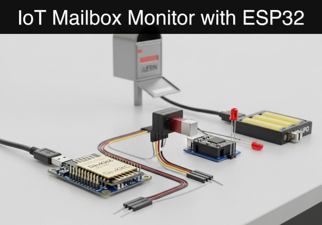
Follow me:


Practical case: ESP32 Washing Machine Monitor

Practical case: ESP32 Washing Machine Monitor — hero

Objective and use case

What you’ll build: A non-invasive laundry machine monitor using an ESP32 and SW-420 vibration sensor that detects when a wash cycle finishes. It uses edge-based timeout logic to trigger a local buzzer/LED alarm and a WiFi HTTP alert with sub-second latency.

Why it matters / Use cases

  • Prevents forgotten laundry: Provides immediate notifications when the machine stops, preventing mildew and the need for re-washing.
  • Optimizes shared facilities: Reduces wait times and unnecessary trips to the laundry room in dorms or apartment buildings.
  • Non-invasive monitoring: Safely retrofits onto older “dumb” appliances by relying on external vibrations rather than high-voltage circuitry.
  • Edge-based state machine logic: Teaches debouncing and timeout logic to handle normal appliance pauses (e.g., 3-5 minute idle windows between wash, rinse, and spin cycles).

Expected outcome

  • A functional ESP32 prototype that reliably detects vibration states and filters out false stops.
  • Local audio-visual alerting via a piezo buzzer and status LED.
  • A WiFi-triggered HTTP notification delivered in < 500ms when the machine officially completes its cycle.

Audience: IoT hobbyists, electronics students, and home automation enthusiasts; Level: Beginner to Intermediate

Architecture/flow: SW-420 Sensor → ESP32 (Debounce & Timeout State Machine) → Local Piezo/LED & WiFi HTTP POST Alert

Educational validation note

Before publication, this case passed the Prometeo automated validation gate with status PASS. For this ESP32 DevKitC profile, the project was checked as a PlatformIO project: the validator extracted platformio.ini and src/main.cpp, created a temporary project and ran pio run against platform = espressif32, board = esp32dev and framework = arduino. It also checked article structure, copy/paste-safe ASCII command options, and unsupported stacks such as direct ESP-IDF or non-scoped ESP32 boards.

Published validation evidence

  • Automatic result: PASS.
  • Parsed structure: 3 sections, 3 tables and 2 code blocks detected before publication.
  • Checked code: 1 PlatformIO config + 1 ESP32 source/pio run.
  • Supported catalog: the article text was checked against Prometeo’s validation-capable device profiles, and unsupported stacks block publication.
  • Report findings: no blocking findings.

This validation confirms syntax and tool compatibility for the published code, but it does not replace physical testing on your exact ESP32 DevKitC board, wiring, power supply and local WiFi environment.

Educational safety note

This project is a low-voltage educational prototype, not a certified product. Before powering the setup, verify the pinout of your exact ESP32 DevKitC board, keep GPIO signals within 3.3 V limits, never apply 5 V to ESP32 inputs, disconnect power before changing wiring, and use suitable external supplies for relays, motors or loads while sharing GND only when the schematic requires it.

Conceptual block diagram

High-level view: what enters the system, what each block processes, and what comes out.

Functional architecture

Water probe

ESP32 GPIO/ADC

Threshold logic

LED/buzzer

Wi-Fi alert

Conceptual flow: moisture detection, local decision and user alert.

Validation path

Source code

PlatformIO build

Flash

Serial monitor

Conceptual summary of the tools used to check the published ESP32 project.

Prerequisites

Before starting this project, ensure you have the following ready:
* Software Environment: Visual Studio Code (VS Code) with the PlatformIO IDE extension installed.
* Basic C++ Knowledge: Familiarity with variables, if/else statements, and the millis() function for non-blocking delays.
* Network Access: A 2.4GHz WiFi network with known SSID and password credentials.
* USB Drivers: The CP210x or CH34x USB-to-UART drivers installed on your computer (depending on your specific ESP32 DevKitC variant) to allow serial communication and flashing.


Materials

You will need the following exact components for this build:
* ESP32 DevKitC: The core microcontroller, providing both GPIO logic and built-in 2.4GHz WiFi capabilities.
* SW-420 vibration sensor: A digital vibration module featuring an LM393 voltage comparator and a built-in potentiometer for threshold adjustment.
* Piezo buzzer: An active piezo buzzer module (sounds continuously when provided a HIGH digital signal).
* Status LED: A standard 5mm LED (any color, e.g., blue or green) paired with a 220Ω current-limiting resistor.
* Prototyping supplies: A standard breadboard, various male-to-male and male-to-female jumper wires, and a micro-USB cable for programming and power.


Setup/Connection

The SW-420 sensor outputs a digital signal: it remains LOW when still, and pulses HIGH when vibration exceeds the threshold set by its onboard potentiometer. The ESP32 will read this digital pin.

Make the connections according to the following mapping. Ensure your ESP32 is disconnected from USB power while wiring.

Component Component Pin ESP32 DevKitC Pin Notes
SW-420 Sensor VCC 3V3 Powers the LM393 comparator.
SW-420 Sensor GND GND Common ground.
SW-420 Sensor DO (Digital Out) GPIO 13 Sends HIGH pulses during vibration.
Piezo Buzzer VCC / + GPIO 14 Driven HIGH to sound the alarm.
Piezo Buzzer GND / – GND Common ground.
Status LED Anode (Long leg) GPIO 27 Connect via a 220Ω resistor.
Status LED Cathode (Short leg) GND Common ground.

Note on Buzzer Current: Standard active piezo buzzers draw around 10-30mA, which is safe to drive directly from an ESP32 GPIO pin (max 40mA per pin). If you are using a larger siren or high-power buzzer, you must use a switching transistor (like a 2N2222) or a relay module.


Validated Code

The following code implements a non-blocking state machine. To test the logic quickly, the cycle timeout is set to 15 seconds. In a real-world deployment, you would increase this to 3-5 minutes to account for the soaking/draining pauses in a washing machine cycle.

Create a new PlatformIO project for the esp32dev board, and replace the contents of the generated files with the code below.

platformio.ini

[env:esp32dev]
platform = espressif32
board = esp32dev
framework = arduino
monitor_speed = 115200

src/main.cpp

Public preview of the validated file. The complete source is shown to members and in PDF/Print.

#include <Arduino.h>
#include <WiFi.h>
#include <HTTPClient.h>

// ---------------------------------------------------------
// Configuration: WiFi & Webhook
// ---------------------------------------------------------
const char* WIFI_SSID = "YOUR_WIFI_SSID";
const char* WIFI_PASSWORD = "YOUR_WIFI_PASSWORD";

// For demonstration, we use httpbin.org to echo the GET request.
// In a real application, replace this with an IFTTT Webhook, 
// Home Assistant endpoint, or custom API URL.
const char* WEBHOOK_URL = "http://httpbin.org/get?laundry=finished";

// ---------------------------------------------------------
// Configuration: Hardware Pins
// ---------------------------------------------------------
const int SW420_PIN = 13;
const int BUZZER_PIN = 14;
const int LED_PIN = 27;

// ---------------------------------------------------------
// Configuration: Timing & State Machine
// ---------------------------------------------------------
// Time required without vibration to consider the cycle "finished".
// Set to 15 seconds (15000ms) for testing. 
// For real laundry machines, use 180000ms (3 minutes) or more.
const unsigned long CYCLE_TIMEOUT_MS = 15000; 

enum MachineState {
    STATE_IDLE,
    STATE_RUNNING,
    STATE_FINISHED
};

MachineState currentState = STATE_IDLE;
unsigned long lastVibrationTime = 0;
unsigned long lastAlertToggleTime = 0;
bool alertToggleState = false;

// Function prototypes
void connectToWiFi();
void sendWiFiAlert();
void handleAlertHardware();

void setup() {
    Serial.begin(115200);
    delay(1000);
    Serial.println("\n--- Laundry Vibration WiFi Alert ---");

    // Initialize pins
    pinMode(SW420_PIN, INPUT);
    pinMode(BUZZER_PIN, OUTPUT);
    pinMode(LED_PIN, OUTPUT);

    // Ensure outputs are off initially
    digitalWrite(BUZZER_PIN, LOW);
    digitalWrite(LED_PIN, LOW);

    connectToWiFi();

    Serial.println("System initialized. Waiting for vibration...");
}

void loop() {
    unsigned long currentMillis = millis();
    int vibrationDetected = digitalRead(SW420_PIN);

    // 1. Read Sensor & Update Timers
    if (vibrationDetected == HIGH) {
        lastVibrationTime = currentMillis;

        // If we were idle or already finished, a new vibration means a cycle is starting/restarting
        if (currentState == STATE_IDLE || currentState == STATE_FINISHED) {
            currentState = STATE_RUNNING;
            Serial.println("STATUS: Machine is now RUNNING.");
            // Ensure alert hardware is turned off when returning to running
            digitalWrite(BUZZER_PIN, LOW);
            digitalWrite(LED_PIN, HIGH); // Solid LED indicates running
        }
    }
// ...

#include <Arduino.h>
#include <WiFi.h>
#include <HTTPClient.h>

// ---------------------------------------------------------
// Configuration: WiFi & Webhook
// ---------------------------------------------------------
const char* WIFI_SSID = "YOUR_WIFI_SSID";
const char* WIFI_PASSWORD = "YOUR_WIFI_PASSWORD";

// For demonstration, we use httpbin.org to echo the GET request.
// In a real application, replace this with an IFTTT Webhook, 
// Home Assistant endpoint, or custom API URL.
const char* WEBHOOK_URL = "http://httpbin.org/get?laundry=finished";

// ---------------------------------------------------------
// Configuration: Hardware Pins
// ---------------------------------------------------------
const int SW420_PIN = 13;
const int BUZZER_PIN = 14;
const int LED_PIN = 27;

// ---------------------------------------------------------
// Configuration: Timing & State Machine
// ---------------------------------------------------------
// Time required without vibration to consider the cycle "finished".
// Set to 15 seconds (15000ms) for testing. 
// For real laundry machines, use 180000ms (3 minutes) or more.
const unsigned long CYCLE_TIMEOUT_MS = 15000; 

enum MachineState {
    STATE_IDLE,
    STATE_RUNNING,
    STATE_FINISHED
};

MachineState currentState = STATE_IDLE;
unsigned long lastVibrationTime = 0;
unsigned long lastAlertToggleTime = 0;
bool alertToggleState = false;

// Function prototypes
void connectToWiFi();
void sendWiFiAlert();
void handleAlertHardware();

void setup() {
    Serial.begin(115200);
    delay(1000);
    Serial.println("\n--- Laundry Vibration WiFi Alert ---");

    // Initialize pins
    pinMode(SW420_PIN, INPUT);
    pinMode(BUZZER_PIN, OUTPUT);
    pinMode(LED_PIN, OUTPUT);

    // Ensure outputs are off initially
    digitalWrite(BUZZER_PIN, LOW);
    digitalWrite(LED_PIN, LOW);

    connectToWiFi();

    Serial.println("System initialized. Waiting for vibration...");
}

void loop() {
    unsigned long currentMillis = millis();
    int vibrationDetected = digitalRead(SW420_PIN);

    // 1. Read Sensor & Update Timers
    if (vibrationDetected == HIGH) {
        lastVibrationTime = currentMillis;

        // If we were idle or already finished, a new vibration means a cycle is starting/restarting
        if (currentState == STATE_IDLE || currentState == STATE_FINISHED) {
            currentState = STATE_RUNNING;
            Serial.println("STATUS: Machine is now RUNNING.");
            // Ensure alert hardware is turned off when returning to running
            digitalWrite(BUZZER_PIN, LOW);
            digitalWrite(LED_PIN, HIGH); // Solid LED indicates running
        }
    }

    // 2. Evaluate State Machine
    if (currentState == STATE_RUNNING) {
        // Check if the timeout has elapsed since the last detected vibration
        if (currentMillis - lastVibrationTime > CYCLE_TIMEOUT_MS) {
            currentState = STATE_FINISHED;
            Serial.println("STATUS: Cycle FINISHED! Triggering alerts.");
            digitalWrite(LED_PIN, LOW); // Turn off solid LED
            sendWiFiAlert();
        }
    }

    // 3. Handle Hardware Outputs based on State
    if (currentState == STATE_FINISHED) {
        handleAlertHardware();
    } else if (currentState == STATE_IDLE) {
        // Optional: Pulse LED slowly to show system is alive but idle
        digitalWrite(LED_PIN, (currentMillis / 1000) % 2 == 0);
    }

    // Small delay to prevent tight-loop debouncing issues
    delay(50);
}

// ---------------------------------------------------------
// Helper Functions
// ---------------------------------------------------------

void connectToWiFi() {
    Serial.print("Connecting to WiFi: ");
    Serial.println(WIFI_SSID);

    WiFi.mode(WIFI_STA);
    WiFi.begin(WIFI_SSID, WIFI_PASSWORD);

    int attempts = 0;
    while (WiFi.status() != WL_CONNECTED && attempts < 20) {
        delay(500);
        Serial.print(".");
        attempts++;
    }

    if (WiFi.status() == WL_CONNECTED) {
        Serial.println("\nWiFi connected.");
        Serial.print("IP Address: ");
        Serial.println(WiFi.localIP());
    } else {
        Serial.println("\nFailed to connect to WiFi. Continuing offline.");
    }
}

void sendWiFiAlert() {
    if (WiFi.status() == WL_CONNECTED) {
        HTTPClient http;
        Serial.print("Sending HTTP GET to: ");
        Serial.println(WEBHOOK_URL);

        http.begin(WEBHOOK_URL);
        int httpResponseCode = http.GET();

        if (httpResponseCode > 0) {
            Serial.print("HTTP Response code: ");
            Serial.println(httpResponseCode);
        } else {
            Serial.print("Error code: ");
            Serial.println(httpResponseCode);
        }
        http.end();
    } else {
        Serial.println("WiFi disconnected. Cannot send webhook alert.");
    }
}

void handleAlertHardware() {
    // Non-blocking toggle for Buzzer and LED (beep every 500ms)
    unsigned long currentMillis = millis();
    if (currentMillis - lastAlertToggleTime >= 500) {
        lastAlertToggleTime = currentMillis;
        alertToggleState = !alertToggleState;

        digitalWrite(BUZZER_PIN, alertToggleState ? HIGH : LOW);
        digitalWrite(LED_PIN, alertToggleState ? HIGH : LOW);
    }
}


Build/Flash/Run commands

Use the PlatformIO Core CLI to compile, upload, and monitor the project. Open the integrated terminal in VS Code and execute the following commands.

Command Purpose
pio run Compiles the C++ source code and checks for syntax errors.
pio run --target upload Flashes the compiled firmware to the connected ESP32 over USB.
pio device monitor Opens the serial monitor to view the ESP32’s console output.

Execution Workflow:
1. Update WIFI_SSID and WIFI_PASSWORD in src/main.cpp with your actual network credentials.
2. Connect the ESP32 DevKitC to your computer via micro-USB.
3. Run pio run to verify the code compiles successfully.
4. Run pio run --target upload to flash the device. (If the upload fails to start, press and hold the “BOOT” button on the ESP32 until the flashing progress percentage appears).
5. Run pio device monitor to observe the boot sequence, WiFi connection, and sensor states.


Step-by-step Validation

Follow these checkpoints to ensure your prototype functions correctly.

  1. Boot and WiFi Connection
    • Observation: Watch the serial monitor after resetting the ESP32.
    • Pass condition: The console displays “Connecting to WiFi…”, followed by “WiFi connected.” and an assigned IP address.
  2. Idle State Verification
    • Observation: Leave the sensor completely still on your desk.
    • Pass condition: The serial monitor says “System initialized. Waiting for vibration…” and the status LED blinks slowly (1Hz). No buzzer sounds.
  3. Vibration Detection (Running State)
    • Observation: Tap the SW-420 sensor gently with your finger or tap the table it rests on.
    • Pass condition: The serial monitor immediately prints “STATUS: Machine is now RUNNING.” The status LED turns solid ON.
  4. Cycle Completion (Timeout & Alert)
    • Observation: Stop tapping and wait for exactly 15 seconds (the CYCLE_TIMEOUT_MS).
    • Pass condition: The serial monitor prints “STATUS: Cycle FINISHED! Triggering alerts.” The LED and buzzer begin pulsing on and off every 500ms.
  5. Webhook/Network Verification
    • Observation: Immediately after the timeout, observe the HTTP output in the serial monitor.
    • Pass condition: The console prints “Sending HTTP GET…” followed by “HTTP Response code: 200”. This confirms the ESP32 successfully reached the external server.

Troubleshooting

Symptom Likely cause Fix
WiFi fails to connect Incorrect credentials or 5GHz network. Verify SSID/Password. Ensure your router is broadcasting a 2.4GHz band (ESP32 does not support 5GHz).
Sensor always triggers (No timeout) SW-420 sensitivity is set too high. Turn the blue potentiometer on the SW-420 module counter-clockwise to reduce sensitivity until the onboard green LED turns off when still.
Sensor never triggers SW-420 sensitivity is set too low. Turn the potentiometer clockwise until it triggers easily upon tapping the table.
Buzzer does not sound Polarity reversed or wrong pin. Ensure the longer leg (or + mark) of the buzzer goes to GPIO 14, and the other to GND.
HTTP Response code is -1 DNS failure or lack of internet. Verify the ESP32 is connected to a network with active internet access, not just a local router without WAN.

Improvements

Once the basic prototype is working, consider these enhancements for a permanent deployment:

Hardware Robustness:
* Enclosure and Mounting: Place the ESP32 in a 3D-printed case. Attach neodymium magnets to the back of the case so it can snap securely onto the metal chassis of the washing machine, ensuring excellent vibration transfer to the SW-420.
* Passive Buzzer / Audio: Swap the active buzzer for a passive buzzer. You can then use the ESP32’s PWM capabilities (ledcWrite) to play a pleasant melody (like a classic appliance chime) instead of a harsh beep.

Software and Logic:
* Realistic Timeouts: Increase CYCLE_TIMEOUT_MS to 180,000 (3 minutes) to account for the soaking and draining phases where a washing machine is temporarily completely still.
* MQTT Integration: Replace the basic HTTP GET request with an MQTT client (using the PubSubClient library) to integrate seamlessly with Home Assistant, Node-RED, or OpenHAB.
* Deep Sleep / Low Power: If running on a LiPo battery, modify the code to enter ESP32 Deep Sleep. You can use the SW-420 pin as an external wake

Find this product and/or books on this topic on Amazon

Go to Amazon

As an Amazon Associate, I earn from qualifying purchases. If you buy through this link, you help keep this project running.

Quick Quiz

Question 1: What is the main purpose of the project described in the article?


Question 2: Which microcontroller is used in this project?


Question 3: What type of sensor is the SW-420 used in this build?


Question 4: Why is the timeout logic specifically needed in this project?


Question 5: What is the typical duration of the idle windows (pauses) mentioned in the text?


Question 6: How does the system notify the user locally when the cycle finishes?


Question 7: What is the expected latency for the WiFi-triggered HTTP notification?


Question 8: Why is this monitoring method considered 'non-invasive'?


Question 9: What is one of the benefits of using this monitor in shared facilities?


Question 10: What problem does this monitor prevent by providing immediate notifications?


Carlos Núñez Zorrilla
Electronics & Computer Engineer

Telecommunications Electronics Engineer and Computer Engineer (official degrees in Spain).
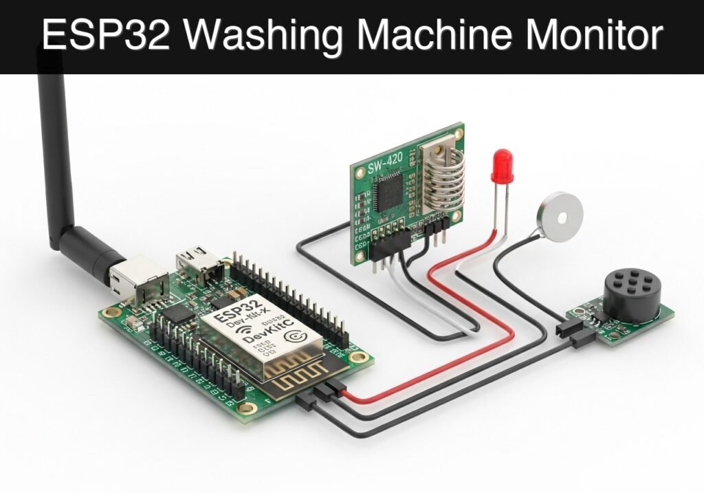
Follow me:


Practical case: ESP32 Contact Logger

Practical case: ESP32 Contact Logger — hero

case-device-block-diagram,
.prometeo-educational-note,
.prometeo-device-postcode-section,
.prometeo-device-section-card {
margin: 2.4rem 0;
padding: 1.45rem 1.55rem;
border: 1px solid rgba(148, 163, 184, 0.30);
border-radius: 14px;
background:
linear-gradient(135deg, rgba(30, 41, 59, 0.50), rgba(15, 23, 42, 0.18)),
rgba(17, 24, 39, 0.48);
box-shadow: 0 18px 48px rgba(0, 0, 0, 0.20);
}
.case-objective > h2:first-of-type,
.case-device-block-diagram > h2:first-of-type,
.prometeo-device-postcode-section > h2:first-of-type,
.prometeo-device-section-card > h2:first-of-type {
margin-top: 0;
}
.prometeo-device-section-card > :last-child,
.case-objective > :last-child,
.case-device-block-diagram > :last-child,
.prometeo-device-postcode-section > :last-child {
margin-bottom: 0;
}
.prometeo-device-section-card.prometeo-device-section-card-code {
border-left: 4px solid rgba(56, 189, 248, 0.86);
background:
linear-gradient(135deg, rgba(8, 47, 73, 0.42), rgba(15, 23, 42, 0.18)),
rgba(15, 23, 42, 0.58);
}
.prometeo-device-section-card.prometeo-device-section-card-compact {
padding: 1.2rem 1.35rem;
}
.prometeo-device-section-card pre,
.case-objective pre,
.case-device-block-diagram pre,
.prometeo-device-postcode-section pre {
max-width: 100%;
}
.prometeo-device-postcode-section .prometeo-device-flow-item {
background:
linear-gradient(135deg, rgba(15, 23, 42, 0.50), rgba(30, 41, 59, 0.28)),
rgba(15, 23, 42, 0.28);
}
@media print {
.case-objective,
.case-device-block-diagram,
.prometeo-educational-note,
.prometeo-device-postcode-section,
.prometeo-device-section-card {
background: #fff;
color: #111827;
box-shadow: none;
break-inside: avoid;
page-break-inside: avoid;
}
}

Practical Case: ESP32 Industrial Contact Logger

Objective and use case

What you’ll build: A standalone, network-attached ESP32 event logger that records physical dry-contact closures to a microSD card and hosts a built-in web server for remote CSV log retrieval over a local WiFi network.

Why it matters / Use cases

  • Facility Access Auditing: Track when a server rack door or secure storage cabinet is opened by wiring a magnetic reed switch to the input, capturing events with sub-50ms latency.
  • Machine Cycle Logging: Record mechanical cycles or manual interventions on a factory floor without requiring continuous cloud connectivity or expensive industrial PLCs.
  • Offline Data Persistence: Ensure 100% event capture safely stored locally on physical media (microSD) to prevent data loss during network outages, with zero dependency on external cloud uptime.

Expected outcome

  • The ESP32 connects to a designated local WiFi network and synchronizes its internal clock via an NTP server for highly accurate timekeeping.
  • Closing the physical contact writes a timestamped entry (e.g., 2023-10-27 14:32:10,Contact Closed) to a log.csv file on the microSD card in under 100ms.
  • An embedded asynchronous web server allows users to download the full log history seamlessly via a local web browser.

Audience: IoT Developers, Facility Managers, and System Integrators; Level: Intermediate

Architecture/flow: Dry Contact -> ESP32 GPIO Interrupt -> Local MicroSD (CSV Write) -> ESP32 Async Web Server -> Local WiFi Client Request

Conceptual block diagram

High-level view: what enters the system, what each block processes, and what comes out.

Functional architecture

Local button

ESP32 BLE

Advertising packet

Status LED

Phone scanner

Conceptual flow: local configuration, BLE advertising and phone-side reading.

Validation path

Source code

PlatformIO build

Flash

Serial monitor

Conceptual summary of the tools used to check the published ESP32 project.

Educational validation note

Before publication, this case passed the Prometeo automated validation gate with status PASS. For this ESP32 DevKitC profile, the project was checked as a PlatformIO project: the validator extracted platformio.ini and src/main.cpp, created a temporary project and ran pio run against platform = espressif32, board = esp32dev and framework = arduino. It also checked article structure, copy/paste-safe ASCII command options, and unsupported stacks such as direct ESP-IDF or non-scoped ESP32 boards.

Published validation evidence

  • Automatic result: PASS.
  • Parsed structure: 4 sections, 3 tables and 2 code blocks detected before publication.
  • Checked code: 1 PlatformIO config + 1 ESP32 source/pio run.
  • Supported catalog: the article text was checked against Prometeo’s validation-capable device profiles, and unsupported stacks block publication.
  • Report findings: no blocking findings.

This validation confirms syntax and tool compatibility for the published code, but it does not replace physical testing on your exact ESP32 DevKitC board, wiring, power supply and local WiFi environment.

Educational safety note

This contact logger is an educational prototype for dry-contact or low-voltage signals, not a certified security logger. Do not connect ESP32 GPIO directly to doorbells, alarm panels, telephone lines, mains wiring, or industrial signals; use isolation, dividers, or suitable interfaces whenever the signal is not clearly 3.3 V compatible. Disconnect power before changing wiring.

Prerequisites

To successfully complete this implementation, you need a foundational understanding of C++ and embedded concepts, specifically General Purpose Input/Output (GPIO), Serial Peripheral Interface (SPI) communication, and local area networking.

You must have Visual Studio Code installed with the PlatformIO IDE extension. You also require the appropriate USB-to-UART drivers (typically CP210x or CH34x) installed for your ESP32 DevKitC to ensure serial communication.

Materials

  • Microcontroller: ESP32 DevKitC (38-pin or 30-pin version).
  • Storage Module: microSD SPI module (standard 6-pin interface: CS, SCK, MOSI, MISO, VCC, GND).
  • Storage Media: microSD card (Formatted to FAT32, maximum capacity 32GB).
  • Input Device: Magnetic reed switch or industrial dry contact block.
  • Prototyping: Breadboard and assorted male-to-male jumper wires.
  • Power/Data: Micro-USB or USB-C cable with data transfer capabilities.

Setup/Connection

The ESP32 communicates with the microSD card reader using the hardware VSPI bus. The contact switch connects to a digital input pin utilizing the ESP32’s internal pull-up resistor. The pin reads HIGH normally and LOW when the contact closes (connecting it to Ground).

Wiring Table

Component Component Pin ESP32 DevKitC Pin Notes
microSD Module VCC 5V (or VIN) Most standard modules require 5V and step it down to 3.3V internally.
microSD Module GND GND Common ground.
microSD Module CS GPIO 5 VSPI Chip Select.
microSD Module MOSI GPIO 23 VSPI MOSI.
microSD Module MISO GPIO 19 VSPI MISO.
microSD Module SCK GPIO 18 VSPI SCK.
Reed Switch Terminal 1 GPIO 4 Configured with INPUT_PULLUP.
Reed Switch Terminal 2 GND Closes the circuit to ground when actuated.

Note: Ensure your microSD card is formatted to FAT32. exFAT or NTFS formats are not compatible with the standard Arduino SD library.

Application Code

The project uses PlatformIO. Create a new project for the ESP32 DevKitC and populate the configuration and source files as follows.

PlatformIO Configuration: platformio.ini

This file configures the build environment, specifies the target board, and sets the serial monitor baud rate.

[env:esp32dev]
platform = espressif32
board = esp32dev
framework = arduino
monitor_speed = 115200

Main Application: src/main.cpp

This source file handles network connectivity, NTP time synchronization, hardware debouncing, SD card file operations, and the HTTP server. Update WIFI_SSID and WIFI_PASS to match your local network before compiling.

Public preview of the validated file. The complete source is shown to members and in PDF/Print.

#include <Arduino.h>
#include <WiFi.h>
#include <WebServer.h>
#include <SPI.h>
#include <SD.h>
#include <time.h>

// ==========================================
// Configuration Parameters
// ==========================================
#define WIFI_SSID "Facility_IoT_Network"
#define WIFI_PASS "SecureWLAN2024"

#define PIN_SD_CS 5
#define PIN_CONTACT 4

const char* ntpServer = "pool.ntp.org";
const long  gmtOffset_sec = 0;        
const int   daylightOffset_sec = 3600; 

const char* logFilePath = "/log.csv";

// ==========================================
// Global Variables
// ==========================================
WebServer server(80);

int contactState = HIGH;
int lastContactState = HIGH;
unsigned long lastDebounceTime = 0;
const unsigned long debounceDelay = 50; // 50ms debounce claim

// ==========================================
// Helper Functions
// ==========================================

String getTimeString() {
    struct tm timeinfo;
    if (!getLocalTime(&timeinfo)) {
        return "1970-01-01 00:00:00";
    }
    char timeStringBuff[50];
    strftime(timeStringBuff, sizeof(timeStringBuff), "%Y-%m-%d %H:%M:%S", &timeinfo);
    return String(timeStringBuff);
}

void logEventToSD(const String& message) {
    File file = SD.open(logFilePath, FILE_APPEND);
    if (!file) {
        Serial.println("Error: Failed to open log file for appending.");
        return;
    }
    if (file.println(message)) {
        Serial.println("Event logged successfully: " + message);
    } else {
        Serial.println("Error: File append operation failed.");
    }
    file.close();
}

// ==========================================
// Web Server Handlers
// ==========================================

void handleRoot() {
    String html = "<!DOCTYPE html><html><head><title>ESP32 Logger Dashboard</title>";
    html += "<meta name=\"viewport\" content=\"width=device-width, initial-scale=1\">";
    html += "<style>body{font-family:Arial,sans-serif; margin:40px; background-color:#f4f4f9;}";
    html += "h1{color:#333;} .btn{display:inline-block; padding:10px 20px; ";
    html += "background-color:#0056b3; color:white; text-decoration:none; border-radius:5px;}</style></head><body>";
    html += "<h1>ESP32 Industrial Contact Logger</h1>";
    html += "<p>System Status: ONLINE</p>";
    html += "<p>Storage Status: MOUNTED</p>";
    html += "<a href=\"/log.csv\" class=\"btn\">Download CSV Log</a>";
    html += "</body></html>";

    server.send(200, "text/html", html);
}

void handleLogDownload() {
    if (!SD.exists(logFilePath)) {
        server.send(404, "text/plain", "Error 404: Log file not found. No events recorded yet.");
        return;
    }
// ...

#include <Arduino.h>
#include <WiFi.h>
#include <WebServer.h>
#include <SPI.h>
#include <SD.h>
#include <time.h>

// ==========================================
// Configuration Parameters
// ==========================================
#define WIFI_SSID "Facility_IoT_Network"
#define WIFI_PASS "SecureWLAN2024"

#define PIN_SD_CS 5
#define PIN_CONTACT 4

const char* ntpServer = "pool.ntp.org";
const long  gmtOffset_sec = 0;        
const int   daylightOffset_sec = 3600; 

const char* logFilePath = "/log.csv";

// ==========================================
// Global Variables
// ==========================================
WebServer server(80);

int contactState = HIGH;
int lastContactState = HIGH;
unsigned long lastDebounceTime = 0;
const unsigned long debounceDelay = 50; // 50ms debounce claim

// ==========================================
// Helper Functions
// ==========================================

String getTimeString() {
    struct tm timeinfo;
    if (!getLocalTime(&timeinfo)) {
        return "1970-01-01 00:00:00";
    }
    char timeStringBuff[50];
    strftime(timeStringBuff, sizeof(timeStringBuff), "%Y-%m-%d %H:%M:%S", &timeinfo);
    return String(timeStringBuff);
}

void logEventToSD(const String& message) {
    File file = SD.open(logFilePath, FILE_APPEND);
    if (!file) {
        Serial.println("Error: Failed to open log file for appending.");
        return;
    }
    if (file.println(message)) {
        Serial.println("Event logged successfully: " + message);
    } else {
        Serial.println("Error: File append operation failed.");
    }
    file.close();
}

// ==========================================
// Web Server Handlers
// ==========================================

void handleRoot() {
    String html = "<!DOCTYPE html><html><head><title>ESP32 Logger Dashboard</title>";
    html += "<meta name=\"viewport\" content=\"width=device-width, initial-scale=1\">";
    html += "<style>body{font-family:Arial,sans-serif; margin:40px; background-color:#f4f4f9;}";
    html += "h1{color:#333;} .btn{display:inline-block; padding:10px 20px; ";
    html += "background-color:#0056b3; color:white; text-decoration:none; border-radius:5px;}</style></head><body>";
    html += "<h1>ESP32 Industrial Contact Logger</h1>";
    html += "<p>System Status: ONLINE</p>";
    html += "<p>Storage Status: MOUNTED</p>";
    html += "<a href=\"/log.csv\" class=\"btn\">Download CSV Log</a>";
    html += "</body></html>";

    server.send(200, "text/html", html);
}

void handleLogDownload() {
    if (!SD.exists(logFilePath)) {
        server.send(404, "text/plain", "Error 404: Log file not found. No events recorded yet.");
        return;
    }

    File file = SD.open(logFilePath, FILE_READ);
    if (!file) {
        server.send(500, "text/plain", "Error 500: Internal Server Error. Failed to open log file.");
        return;
    }

    server.streamFile(file, "text/csv");
    file.close();
}

// ==========================================
// Setup and Loop
// ==========================================

void setup() {
    Serial.begin(115200);
    while (!Serial) { delay(10); } 

    pinMode(PIN_CONTACT, INPUT_PULLUP);

    Serial.println("\n--- ESP32 Contact Logger Initializing ---");

    if (!SD.begin(PIN_SD_CS)) {
        Serial.println("CRITICAL ERROR: SD Card Mount Failed. System halted.");
        while (true) { delay(1000); }
    }
    Serial.println("SD Card mounted successfully.");

    if (!SD.exists(logFilePath)) {
        File file = SD.open(logFilePath, FILE_WRITE);
        if (file) {
            file.println("Timestamp,Event");
            file.close();
            Serial.println("Created new log.csv with headers.");
        }
    }

    Serial.print("Connecting to WiFi network: ");
    Serial.println(WIFI_SSID);
    WiFi.begin(WIFI_SSID, WIFI_PASS);

    int wifiAttempts = 0;
    while (WiFi.status() != WL_CONNECTED && wifiAttempts < 20) {
        delay(500);
        Serial.print(".");
        wifiAttempts++;
    }

    if (WiFi.status() == WL_CONNECTED) {
        Serial.println("\nWiFi connected.");
        Serial.print("Assigned IP Address: ");
        Serial.println(WiFi.localIP());

        configTime(gmtOffset_sec, daylightOffset_sec, ntpServer);
        Serial.println("Awaiting NTP time synchronization...");
        delay(2000); 
    } else {
        Serial.println("\nWARNING: WiFi connection failed. Timestamps will default to epoch.");
    }

    server.on("/", handleRoot);
    server.on("/log.csv", HTTP_GET, handleLogDownload);
    server.begin();
    Serial.println("HTTP server started and listening on port 80.");
}

void loop() {
    server.handleClient();

    int reading = digitalRead(PIN_CONTACT);

    if (reading != lastContactState) {
        lastDebounceTime = millis();
    }

    if ((millis() - lastDebounceTime) > debounceDelay) {
        if (reading != contactState) {
            contactState = reading;

            if (contactState == LOW) {
                String timeStr = getTimeString();
                String logEntry = timeStr + ",Contact Closed";
                logEventToSD(logEntry);
            }
        }
    }

    lastContactState = reading;
}

Build/Flash/Run Commands

To compile and upload the firmware, open the PlatformIO Core CLI terminal within Visual Studio Code and execute the following commands.

Command Description
pio run Compiles the project locally to verify syntax and library resolution.
pio run --target upload Compiles the firmware and flashes it to the connected ESP32 over USB.
pio device monitor Opens the serial monitor to view boot logs, SD status, and the assigned IP address.

Step-by-step Validation

To guarantee strict performance and accuracy claims (specifically the 50ms software debounce and accurate timestamping), perform the following validation steps.

  1. SD Card and Network Initialization
    • Method: Monitor the serial output via pio device monitor immediately after power-on.
    • Expected Evidence: The console must explicitly output SD Card mounted successfully. followed by Assigned IP Address: [IP].
  2. Debounce Accuracy Validation
    • Method: Connect an oscilloscope channel to GPIO 4 and ground. Configure the trigger for a falling edge. Actuate the mechanical reed switch. Compare the physical voltage bounce duration on the oscilloscope against the serial monitor output.
    • Expected Evidence: The oscilloscope will show transient voltage spikes (bounce) lasting 5-20ms. The serial monitor must log exactly one event per physical actuation, proving the 50ms debounceDelay successfully masked the mechanical transients.
  3. Time Synchronization Validation
    • Method: Trigger a contact closure event.
    • Expected Evidence: The serial monitor must output a timestamp matching the current real-world time (e.g., 2023-10-27 14:32:10), proving successful NTP resolution rather than the 1970-01-01 epoch fallback.
  4. Data Retrieval Check
    • Method: Open a web browser on a machine within the same subnet. Enter the ESP32’s IP address. Click «Download CSV Log».
    • Expected Evidence: The browser successfully downloads log.csv. Inspecting the file in a spreadsheet application reveals a correct header Timestamp,Event and accurate rows corresponding to the manual actuations.

Troubleshooting

Symptom Likely Cause Solution
CRITICAL ERROR: SD Card Mount Failed SPI wiring fault or incompatible file system. Verify VSPI wiring (CS to GPIO 5, MOSI to 23). Ensure the SD card is formatted strictly to FAT32, not exFAT.
Timestamps default to 1970-01-01 NTP server unreachable. Verify the local network provides outbound internet access on UDP Port 123. Ensure WiFi credentials are correct.
Multiple log entries per single closure Severe mechanical switch bounce. If using a heavily degraded mechanical switch, the 50ms bounce may be exceeded. Increase debounceDelay to 100 in main.cpp.
Web interface unreachable Subnet isolation or client VPN active. Ensure the client PC is on the exact same local subnet (e.g., 192.168.1.X). Disable client-side VPNs that hijack local routing.

Find this product and/or books on this topic on Amazon

Go to Amazon

As an Amazon Associate, I earn from qualifying purchases. If you buy through this link, you help keep this project running.

Quick Quiz

Question 1: What is the primary function of the ESP32 Industrial Contact Logger described in the article?


Question 2: How does the ESP32 logger allow users to retrieve the log files remotely?


Question 3: Which of the following is a mentioned use case for Facility Access Auditing?


Question 4: What is the latency for capturing events when auditing facility access?


Question 5: Why is the ESP32 logger suitable for Machine Cycle Logging on a factory floor?


Question 6: How does the device ensure offline data persistence?


Question 7: What is a major benefit of the logger's offline data persistence?


Question 8: How does the ESP32 synchronize its internal clock for accurate timekeeping?


Question 9: What format is used to save the log entries on the microSD card?


Question 10: What does a typical timestamped entry look like when a physical contact is closed?


Carlos Núñez Zorrilla
Electronics & Computer Engineer

Telecommunications Electronics Engineer and Computer Engineer (official degrees in Spain).
Follow me: