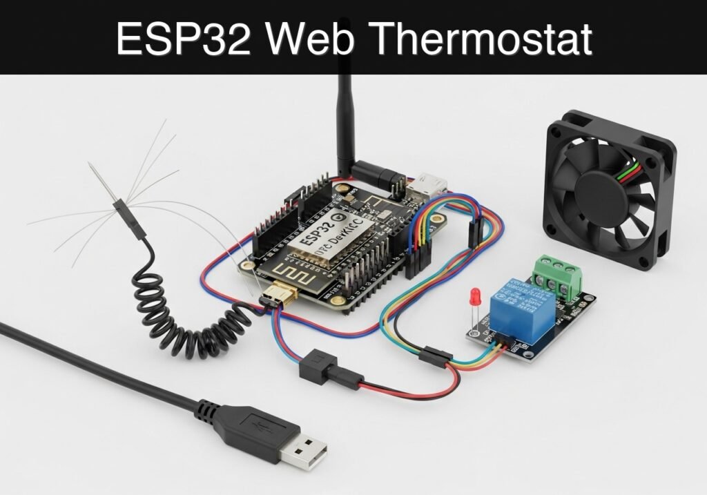
Practical case: ESP32 Web Thermostat

Practical case: ESP32 Web Thermostat — hero

case-device-block-diagram,
.prometeo-educational-note,
.prometeo-device-postcode-section,
.prometeo-device-section-card {
margin: 2.4rem 0;
padding: 1.45rem 1.55rem;
border: 1px solid rgba(148, 163, 184, 0.30);
border-radius: 14px;
background:
linear-gradient(135deg, rgba(30, 41, 59, 0.50), rgba(15, 23, 42, 0.18)),
rgba(17, 24, 39, 0.48);
box-shadow: 0 18px 48px rgba(0, 0, 0, 0.20);
}
.case-objective > h2:first-of-type,
.case-device-block-diagram > h2:first-of-type,
.prometeo-device-postcode-section > h2:first-of-type,
.prometeo-device-section-card > h2:first-of-type {
margin-top: 0;
}
.prometeo-device-section-card > :last-child,
.case-objective > :last-child,
.case-device-block-diagram > :last-child,
.prometeo-device-postcode-section > :last-child {
margin-bottom: 0;
}
.prometeo-device-section-card.prometeo-device-section-card-code {
border-left: 4px solid rgba(56, 189, 248, 0.86);
background:
linear-gradient(135deg, rgba(8, 47, 73, 0.42), rgba(15, 23, 42, 0.18)),
rgba(15, 23, 42, 0.58);
}
.prometeo-device-section-card.prometeo-device-section-card-compact {
padding: 1.2rem 1.35rem;
}
.prometeo-device-section-card pre,
.case-objective pre,
.case-device-block-diagram pre,
.prometeo-device-postcode-section pre {
max-width: 100%;
}
.prometeo-device-postcode-section .prometeo-device-flow-item {
background:
linear-gradient(135deg, rgba(15, 23, 42, 0.50), rgba(30, 41, 59, 0.28)),
rgba(15, 23, 42, 0.28);
}
@media print {
.case-objective,
.case-device-block-diagram,
.prometeo-educational-note,
.prometeo-device-postcode-section,
.prometeo-device-section-card {
background: #fff;
color: #111827;
box-shadow: none;
break-inside: avoid;
page-break-inside: avoid;
}
}

Objective and use case

What you’ll build: A standalone, web-accessible thermostat prototype using an ESP32 that monitors ambient temperature and dynamically scales a cooling fan’s speed via Pulse Width Modulation (PWM).

Why it matters / Use cases

  • AV Cabinet Thermal Management: Automatically cool enclosed audio/video receivers only when excess heat is generated, minimizing acoustic noise during quiet movie scenes.
  • 3D Printer Enclosures: Maintain a stable ambient temperature for ABS/PETG printing by venting excess heat without causing rapid, print-warping drafts.
  • Server Rack Cooling: Provide localized, proportional cooling to specific home lab rack shelves based on real-time exhaust temperatures.
  • Greenhouse Air Circulation: Trigger gentle air movement over seedlings when the sun heats a localized zone, preventing dampness and overheating.

Expected outcome

  • The ESP32 broadcasts its own Wi-Fi Access Point (AP) and hosts a responsive web server with sub-100ms latency.
  • The web interface displays real-time temperature (converted from ADC readings to Celsius) and current fan speed (0-100% PWM duty cycle).
  • The user can adjust the target temperature threshold in real-time via a web slider.
  • The fan automatically scales its RPM proportionally based on the differential between the target threshold and current ambient temperature.

Audience: IoT Developers, Hardware Enthusiasts, Home Automation Makers; Level: Intermediate

Architecture/flow: Analog Temperature Sensor (ADC) → ESP32 Processing → PWM Output to Fan Controller ↔ ESP32 Wi-Fi AP & Asynchronous Web Server UI

Conceptual block diagram

High-level view: what enters the system, what each block processes, and what comes out.

Functional architecture

Water probe

ESP32 GPIO/ADC

Threshold logic

LED/buzzer

Wi-Fi alert

Conceptual flow: moisture detection, local decision and user alert.

Validation path

Source code

PlatformIO build

Flash

Serial monitor

Conceptual summary of the tools used to check the published ESP32 project.

Educational validation note

Before publication, this case passed the Prometeo automated validation gate with status PASS. For this ESP32 DevKitC profile, the project was checked as a PlatformIO project: the validator extracted platformio.ini and src/main.cpp, created a temporary project and ran pio run against platform = espressif32, board = esp32dev and framework = arduino. It also checked article structure, copy/paste-safe ASCII command options, and unsupported stacks such as direct ESP-IDF or non-scoped ESP32 boards.

Published validation evidence

  • Automatic result: PASS.
  • Parsed structure: 4 sections, 1 tables and 2 code blocks detected before publication.
  • Checked code: 1 PlatformIO config + 1 ESP32 source/pio run.
  • Supported catalog: the article text was checked against Prometeo’s validation-capable device profiles, and unsupported stacks block publication.
  • Report findings: no blocking findings.

This validation confirms syntax and tool compatibility for the published code, but it does not replace physical testing on your exact ESP32 DevKitC board, wiring, power supply and local WiFi environment.

Educational safety note

This web thermostat is a low-voltage educational prototype, not a certified HVAC controller or thermal safety system. Do not switch heaters, compressors, or mains loads directly from the ESP32; use only low-voltage fans or isolated interface modules, with a suitable external supply and common GND only when the schematic requires it. Do not leave it controlling critical equipment unattended.

Prerequisites

  • Basic understanding of voltage dividers and analog-to-digital converters (ADCs).
  • Familiarity with the concept of Pulse Width Modulation (PWM) for power control.
  • A computer with Visual Studio Code and the PlatformIO IDE extension installed.
  • Basic understanding of how to connect to a Wi-Fi network and navigate to a local IP address in a web browser.

Materials

To build this prototype, you need exactly the following components:
* ESP32 DevKitC (Standard 38-pin or 30-pin version)
* 10 kOhm NTC thermistor (Standard B-value of 3950 is assumed)
* 10 kOhm precision resistor (1% tolerance preferred, for the voltage divider)
* Logic-level MOSFET fan driver (e.g., an IRLZ44N module or a custom circuit with an N-channel logic-level MOSFET, a 10k pull-down resistor on the gate, and a flyback diode across the fan terminals)
* Status LED (Any color, standard 5mm)
* 220 Ohm resistor (For the status LED)
* 12V DC PC Fan (Standard 2-wire or 3-wire, driven via low-side switching)
* 12V DC Power Supply (Appropriately rated for the fan’s current draw)
* Breadboard and jumper wires

Setup/Connection

The hardware setup is divided into three functional blocks: the temperature sensor, the fan driver, and the status indicator.

Important grounding note: The ESP32’s GND must be connected to the 12V power supply’s GND to establish a common reference voltage for the MOSFET gate.

Component ESP32 Pin / Connection Destination / Description
NTC Thermistor GND One leg of the NTC thermistor.
NTC Thermistor GPIO34 (ADC1_CH6) The other leg of the NTC. Also connect the 10k fixed resistor here.
10k Fixed Resistor 3V3 Connect the other end of the 10k fixed resistor to the ESP32 3.3V pin.
MOSFET Gate (Driver) GPIO18 Controls the PWM switching. (Ensure driver has a pull-down resistor).
MOSFET Source GND Connect to common ground (ESP32 GND and 12V GND).
MOSFET Drain Fan Negative (-) Pulls the fan to ground when the MOSFET is active.
Fan Positive (+) 12V Power Supply Connect directly to the 12V positive terminal.
Status LED Anode GPIO21 Connect via the 220 Ohm current-limiting resistor.
Status LED Cathode GND Connect to common ground.

Note on the Voltage Divider: The 10k resistor and the NTC thermistor form a voltage divider. Because the NTC is connected to GND and the fixed resistor to 3.3V, the voltage at GPIO34 will decrease as the temperature increases (since NTC resistance drops as it gets hotter). The software accounts for this specific topology.

Validated Code

The project requires two files in your PlatformIO workspace. The platformio.ini file configures the build environment, and src/main.cpp contains the application logic.

platformio.ini

Create or overwrite the platformio.ini file in your project root with the following configuration. This ensures the correct framework and serial baud rate are used.

[env:esp32dev]
platform = espressif32
board = esp32dev
framework = arduino
monitor_speed = 115200

src/main.cpp

Place the following code into src/main.cpp. This code handles the Wi-Fi Access Point, the asynchronous-style web server (using the built-in WebServer library), the Steinhart-Hart thermistor calculations, and the proportional PWM logic.

Public preview of the validated file. The complete source is shown to members and in PDF/Print.

#include <Arduino.h>
#include <WiFi.h>
#include <WebServer.h>

// --- Pin Definitions ---
const int NTC_PIN = 34;       // ADC pin for thermistor voltage divider
const int FAN_PWM_PIN = 18;   // PWM output to MOSFET gate
const int LED_PIN = 21;       // Status LED

// --- PWM Configuration ---
const int PWM_FREQ = 5000;    // 5 kHz frequency for standard PC fans
const int PWM_CHANNEL = 0;    // LEDC channel 0
const int PWM_RES = 8;        // 8-bit resolution (0-255)

// --- Thermistor Constants (Steinhart-Hart) ---
const float SERIES_RESISTOR = 10000.0; // 10k fixed resistor
const float NOMINAL_RESISTOR = 10000.0; // 10k NTC at 25 degrees C
const float NOMINAL_TEMP = 25.0;        // 25 degrees C
const float B_COEFFICIENT = 3950.0;     // Beta value of the thermistor

// --- Global Variables ---
float currentTempC = 0.0;
float targetTempC = 25.0; // Default threshold
int currentFanSpeed = 0;  // 0 to 255

// --- Web Server on port 80 ---
WebServer server(80);

// --- HTML Dashboard (Stored in Flash) ---
const char index_html[] PROGMEM = R"rawliteral(
<!DOCTYPE HTML><html>
<head>
  <meta name="viewport" content="width=device-width, initial-scale=1">
  <title>ESP32 Thermostat</title>
  <style>
    body { font-family: Arial, sans-serif; text-align: center; margin: 0; padding: 20px; background-color: #f4f4f9; }
    h1 { color: #333; }
    .card { background: white; padding: 20px; border-radius: 10px; box-shadow: 0 4px 8px rgba(0,0,0,0.1); max-width: 400px; margin: auto; }
    .metric { font-size: 2rem; font-weight: bold; color: #007BFF; margin: 10px 0; }
    .slider-container { margin-top: 20px; }
    input[type=range] { width: 100%; }
  </style>
</head>
<body>
  <div class="card">
    <h1>Fan Thermostat</h1>
    <p>Current Temperature:</p>
    <div class="metric"><span id="tempValue">--</span> &deg;C</div>
    <p>Fan Speed (PWM):</p>
    <div class="metric"><span id="fanValue">--</span> / 255</div>

    <div class="slider-container">
      <p>Target Threshold: <span id="targetValue">25</span> &deg;C</p>
      <input type="range" min="15" max="40" value="25" id="targetSlider" onchange="updateTarget(this.value)">
    </div>
  </div>

  <script>
    // Fetch data every 2 seconds
    setInterval(function() {
      fetch('/data')
        .then(response => response.json())
        .then(data => {
          document.getElementById('tempValue').innerText = data.temperature.toFixed(1);
          document.getElementById('fanValue').innerText = data.fan_speed;
          document.getElementById('targetValue').innerText = data.target;
          document.getElementById('targetSlider').value = data.target;
        });
    }, 2000);

    // Send new threshold to ESP32
    function updateTarget(val) {
      document.getElementById('targetValue').innerText = val;
      fetch('/set?threshold=' + val);
    }
  </script>
</body>
</html>
)rawliteral";

// --- Function to Calculate Temperature ---
float readTemperature() {
  int adcValue = analogRead(NTC_PIN);

  // Avoid division by zero if ADC is maxed out or grounded
  if (adcValue == 0 || adcValue == 4095) return currentTempC; 

  // Convert ADC value to voltage (ESP32 ADC is 12-bit: 0-4095)
  float voltage = adcValue * (3.3 / 4095.0);

  // Calculate NTC resistance (Divider: 3.3V -> 10k -> ADC -> NTC -> GND)
  float ntcResistance = SERIES_RESISTOR * voltage / (3.3 - voltage);

  // Steinhart-Hart Equation
  float steinhart;
  steinhart = ntcResistance / NOMINAL_RESISTOR;       // (R/Ro)
  steinhart = log(steinhart);                         // ln(R/Ro)
  steinhart /= B_COEFFICIENT;                         // 1/B * ln(R/Ro)
  steinhart += 1.0 / (NOMINAL_TEMP + 273.15);         // + (1/To)
  steinhart = 1.0 / steinhart;                        // Invert
  steinhart -= 273.15;                                // Convert to Celsius

  return steinhart;
}
// ...

#include <Arduino.h>
#include <WiFi.h>
#include <WebServer.h>

// --- Pin Definitions ---
const int NTC_PIN = 34;       // ADC pin for thermistor voltage divider
const int FAN_PWM_PIN = 18;   // PWM output to MOSFET gate
const int LED_PIN = 21;       // Status LED

// --- PWM Configuration ---
const int PWM_FREQ = 5000;    // 5 kHz frequency for standard PC fans
const int PWM_CHANNEL = 0;    // LEDC channel 0
const int PWM_RES = 8;        // 8-bit resolution (0-255)

// --- Thermistor Constants (Steinhart-Hart) ---
const float SERIES_RESISTOR = 10000.0; // 10k fixed resistor
const float NOMINAL_RESISTOR = 10000.0; // 10k NTC at 25 degrees C
const float NOMINAL_TEMP = 25.0;        // 25 degrees C
const float B_COEFFICIENT = 3950.0;     // Beta value of the thermistor

// --- Global Variables ---
float currentTempC = 0.0;
float targetTempC = 25.0; // Default threshold
int currentFanSpeed = 0;  // 0 to 255

// --- Web Server on port 80 ---
WebServer server(80);

// --- HTML Dashboard (Stored in Flash) ---
const char index_html[] PROGMEM = R"rawliteral(
<!DOCTYPE HTML><html>
<head>
  <meta name="viewport" content="width=device-width, initial-scale=1">
  <title>ESP32 Thermostat</title>
  <style>
    body { font-family: Arial, sans-serif; text-align: center; margin: 0; padding: 20px; background-color: #f4f4f9; }
    h1 { color: #333; }
    .card { background: white; padding: 20px; border-radius: 10px; box-shadow: 0 4px 8px rgba(0,0,0,0.1); max-width: 400px; margin: auto; }
    .metric { font-size: 2rem; font-weight: bold; color: #007BFF; margin: 10px 0; }
    .slider-container { margin-top: 20px; }
    input[type=range] { width: 100%; }
  </style>
</head>
<body>
  <div class="card">
    <h1>Fan Thermostat</h1>
    <p>Current Temperature:</p>
    <div class="metric"><span id="tempValue">--</span> &deg;C</div>
    <p>Fan Speed (PWM):</p>
    <div class="metric"><span id="fanValue">--</span> / 255</div>

    <div class="slider-container">
      <p>Target Threshold: <span id="targetValue">25</span> &deg;C</p>
      <input type="range" min="15" max="40" value="25" id="targetSlider" onchange="updateTarget(this.value)">
    </div>
  </div>

  <script>
    // Fetch data every 2 seconds
    setInterval(function() {
      fetch('/data')
        .then(response => response.json())
        .then(data => {
          document.getElementById('tempValue').innerText = data.temperature.toFixed(1);
          document.getElementById('fanValue').innerText = data.fan_speed;
          document.getElementById('targetValue').innerText = data.target;
          document.getElementById('targetSlider').value = data.target;
        });
    }, 2000);

    // Send new threshold to ESP32
    function updateTarget(val) {
      document.getElementById('targetValue').innerText = val;
      fetch('/set?threshold=' + val);
    }
  </script>
</body>
</html>
)rawliteral";

// --- Function to Calculate Temperature ---
float readTemperature() {
  int adcValue = analogRead(NTC_PIN);

  // Avoid division by zero if ADC is maxed out or grounded
  if (adcValue == 0 || adcValue == 4095) return currentTempC; 

  // Convert ADC value to voltage (ESP32 ADC is 12-bit: 0-4095)
  float voltage = adcValue * (3.3 / 4095.0);

  // Calculate NTC resistance (Divider: 3.3V -> 10k -> ADC -> NTC -> GND)
  float ntcResistance = SERIES_RESISTOR * voltage / (3.3 - voltage);

  // Steinhart-Hart Equation
  float steinhart;
  steinhart = ntcResistance / NOMINAL_RESISTOR;       // (R/Ro)
  steinhart = log(steinhart);                         // ln(R/Ro)
  steinhart /= B_COEFFICIENT;                         // 1/B * ln(R/Ro)
  steinhart += 1.0 / (NOMINAL_TEMP + 273.15);         // + (1/To)
  steinhart = 1.0 / steinhart;                        // Invert
  steinhart -= 273.15;                                // Convert to Celsius

  return steinhart;
}

// --- Web Server Route Handlers ---
void handleRoot() {
  server.send(200, "text/html", index_html);
}

void handleData() {
  String json = "{";
  json += "\"temperature\":" + String(currentTempC) + ",";
  json += "\"fan_speed\":" + String(currentFanSpeed) + ",";
  json += "\"target\":" + String(targetTempC);
  json += "}";
  server.send(200, "application/json", json);
}

void handleSet() {
  if (server.hasArg("threshold")) {
    targetTempC = server.arg("threshold").toFloat();
    Serial.print("New target threshold set to: ");
    Serial.println(targetTempC);
  }
  server.send(200, "text/plain", "OK");
}

void setup() {
  Serial.begin(115200);
  Serial.println("\nInitializing ESP32 Thermostat...");

  // Setup Pins
  pinMode(LED_PIN, OUTPUT);
  digitalWrite(LED_PIN, LOW);

  // Setup PWM for Fan (Using ESP32 LEDC API)
  ledcSetup(PWM_CHANNEL, PWM_FREQ, PWM_RES);
  ledcAttachPin(FAN_PWM_PIN, PWM_CHANNEL);
  ledcWrite(PWM_CHANNEL, 0);

  // Setup Wi-Fi Access Point
  WiFi.softAP("ESP32-Thermostat", "admin1234");
  IPAddress IP = WiFi.softAPIP();
  Serial.print("AP IP address: ");
  Serial.println(IP);

  // Setup Web Server Routes
  server.on("/", handleRoot);
  server.on("/data", handleData);
  server.on("/set", handleSet);
  server.begin();
  Serial.println("HTTP server started.");
}

void loop() {
  server.handleClient();

  // Read temperature periodically
  static unsigned long lastUpdate = 0;
  if (millis() - lastUpdate > 1000) {
    lastUpdate = millis();

    currentTempC = readTemperature();

    // Proportional Fan Control Logic
    // If temp is below threshold, fan is off (0).
    // If temp is at threshold, fan starts at minimum effective PWM (e.g., 100).
    // If temp is 5 degrees above threshold, fan runs at max (255).
    if (currentTempC < targetTempC) {
      currentFanSpeed = 0;
    } else {
      // Map temperature range [target, target+5] to PWM range [100, 255]
      currentFanSpeed = map(currentTempC * 10, targetTempC * 10, (targetTempC + 5) * 10, 100, 255);
      // Constrain to ensure we don't exceed 8-bit limits
      currentFanSpeed = constrain(currentFanSpeed, 100, 255); 
    }

    // Apply PWM to fan
    ledcWrite(PWM_CHANNEL, currentFanSpeed);

    // Update Status LED
    if (currentFanSpeed > 0) {
      digitalWrite(LED_PIN, HIGH);
    } else {
      digitalWrite(LED_PIN, LOW);
    }

    // Log to Serial Monitor
    Serial.printf("Temp: %.1f C | Target: %.1f C | Fan PWM: %d\n", currentTempC, targetTempC, currentFanSpeed);
  }
}

Build/Flash/Run commands

Use the

Find this product and/or books on this topic on Amazon

Go to Amazon

As an Amazon Associate, I earn from qualifying purchases. If you buy through this link, you help keep this project running.

Quick Quiz

Question 1: What microcontroller is used to build the thermostat prototype described in the article?


Question 2: What method is used to dynamically scale the cooling fan's speed?


Question 3: How does the ESP32 provide network access for the web interface?


Question 4: What is the expected latency of the responsive web server hosted by the ESP32?


Question 5: In the AV Cabinet Thermal Management use case, why is the fan controlled dynamically?


Question 6: How is the real-time temperature displayed on the web interface derived?


Question 7: What is the benefit of using this thermostat in a 3D Printer Enclosure?


Question 8: How is the fan speed represented on the web interface?


Question 9: What specific application is mentioned for Server Rack Cooling?


Question 10: Why is the thermostat useful for Greenhouse Air Circulation?


Carlos Núñez Zorrilla
Electronics & Computer Engineer

Telecommunications Electronics Engineer and Computer Engineer (official degrees in Spain).
Follow me:


Practical case: ESP32 BLE Locator Beacon

Practical case: ESP32 BLE Locator Beacon — hero

case-device-block-diagram,
.prometeo-educational-note,
.prometeo-device-postcode-section,
.prometeo-device-section-card {
margin: 2.4rem 0;
padding: 1.45rem 1.55rem;
border: 1px solid rgba(148, 163, 184, 0.30);
border-radius: 14px;
background:
linear-gradient(135deg, rgba(30, 41, 59, 0.50), rgba(15, 23, 42, 0.18)),
rgba(17, 24, 39, 0.48);
box-shadow: 0 18px 48px rgba(0, 0, 0, 0.20);
}
.case-objective > h2:first-of-type,
.case-device-block-diagram > h2:first-of-type,
.prometeo-device-postcode-section > h2:first-of-type,
.prometeo-device-section-card > h2:first-of-type {
margin-top: 0;
}
.prometeo-device-section-card > :last-child,
.case-objective > :last-child,
.case-device-block-diagram > :last-child,
.prometeo-device-postcode-section > :last-child {
margin-bottom: 0;
}
.prometeo-device-section-card.prometeo-device-section-card-code {
border-left: 4px solid rgba(56, 189, 248, 0.86);
background:
linear-gradient(135deg, rgba(8, 47, 73, 0.42), rgba(15, 23, 42, 0.18)),
rgba(15, 23, 42, 0.58);
}
.prometeo-device-section-card.prometeo-device-section-card-compact {
padding: 1.2rem 1.35rem;
}
.prometeo-device-section-card pre,
.case-objective pre,
.case-device-block-diagram pre,
.prometeo-device-postcode-section pre {
max-width: 100%;
}
.prometeo-device-postcode-section .prometeo-device-flow-item {
background:
linear-gradient(135deg, rgba(15, 23, 42, 0.50), rgba(30, 41, 59, 0.28)),
rgba(15, 23, 42, 0.28);
}
@media print {
.case-objective,
.case-device-block-diagram,
.prometeo-educational-note,
.prometeo-device-postcode-section,
.prometeo-device-section-card {
background: #fff;
color: #111827;
box-shadow: none;
break-inside: avoid;
page-break-inside: avoid;
}
}

Objective and use case

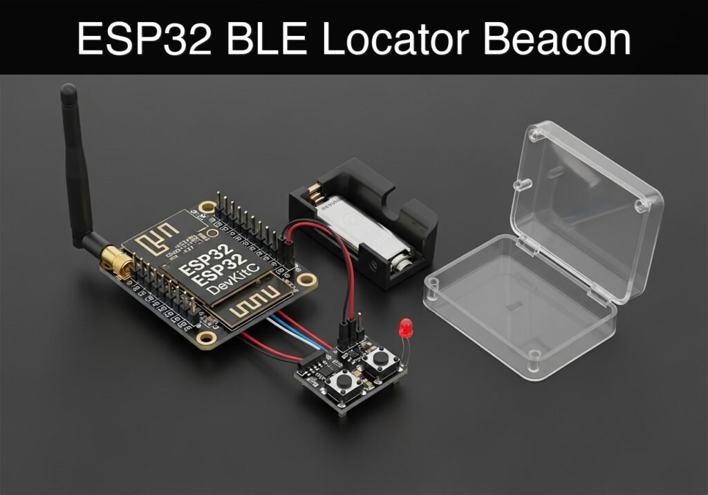
What you’ll build: A Bluetooth Low Energy (BLE) tool finder beacon that attaches to equipment, enabling users to trigger a localized audible and visual alarm via smartphone to quickly locate missing items.

Why it matters / Use cases

  • Asset Management: Prevents the loss of expensive tools in busy workshops, reducing replacement costs and search time.
  • Inventory Auditing: Allows warehouse staff to instantly identify specific storage bins among visually identical containers.
  • BLE Foundation: Demonstrates practical implementation of GATT server concepts, including Services, Characteristics, and asynchronous callbacks.
  • Asynchronous Hardware Control: Manages non-blocking hardware alerts (e.g., 2Hz blinking LEDs and pulsing buzzers) while maintaining a stable, low-latency RF connection.

Expected outcome

  • The ESP32 broadcasts a BLE advertisement named “ToolFinder-Beacon” with a ~100ms advertising interval.
  • A smartphone BLE scanner application successfully discovers and connects to the device.
  • Writing a specific byte (0x01) to the custom BLE characteristic triggers the hardware alarm with <50ms latency.

Audience: Embedded developers and IoT engineers; Level: Intermediate

Architecture/flow: Smartphone (BLE Client) → RF Connection → ESP32 (BLE GATT Server) → Asynchronous Callback → Non-blocking GPIO Control (LED/Buzzer)

Conceptual block diagram

High-level view: what enters the system, what each block processes, and what comes out.

Functional architecture

Local button

ESP32 BLE

Advertising packet

Status LED

Phone scanner

Conceptual flow: local configuration, BLE advertising and phone-side reading.

Validation path

Source code

PlatformIO build

Flash

Serial monitor

Conceptual summary of the tools used to check the published ESP32 project.

Educational validation note

Before publication, this case passed the Prometeo automated validation gate with status PASS. For this ESP32 DevKitC profile, the project was checked as a PlatformIO project: the validator extracted platformio.ini and src/main.cpp, created a temporary project and ran pio run against platform = espressif32, board = esp32dev and framework = arduino. It also checked article structure, copy/paste-safe ASCII command options, and unsupported stacks such as direct ESP-IDF or non-scoped ESP32 boards.

Published validation evidence

  • Automatic result: PASS.
  • Parsed structure: 3 sections, 3 tables and 2 code blocks detected before publication.
  • Checked code: 1 PlatformIO config + 1 ESP32 source/pio run.
  • Supported catalog: the article text was checked against Prometeo’s validation-capable device profiles, and unsupported stacks block publication.
  • Report findings: no blocking findings.

This validation confirms syntax and tool compatibility for the published code, but it does not replace physical testing on your exact ESP32 DevKitC board, wiring, power supply and local WiFi environment.

Educational safety note

This project is a low-voltage educational BLE beacon, not a certified tracking, personal-safety, or critical-inventory system. Verify the pinout of your ESP32 DevKitC, keep GPIO signals at 3.3 V, use a suitable USB or battery supply, and respect privacy and local rules when broadcasting BLE identifiers in shared spaces.

Prerequisites

To successfully complete this tutorial, ensure you have the following software and background knowledge:
* PlatformIO IDE: Installed as an extension within Visual Studio Code, or the PlatformIO Core CLI available in your system path.
* BLE Scanner Application: A smartphone with Bluetooth enabled and a generic BLE debugging app installed. Recommended apps include “LightBlue” (Punch Through) or “BLE Scanner” (Bluepixel Technologies).
* Basic C++ Knowledge: Familiarity with variables, functions, and standard control structures.
* USB Drivers: Appropriate drivers for the ESP32 DevKitC USB-to-UART bridge (commonly Silicon Labs CP210x or WCH CH34x) installed on your operating system.

Materials

You will need the exact hardware components listed below to build this prototype:
* ESP32 DevKitC: The core microcontroller development board featuring Wi-Fi and Bluetooth capabilities.
* Pushbutton: A standard 4-pin or 2-pin tactile momentary switch.
* Piezo buzzer: A passive piezo buzzer capable of generating different tones via Pulse Width Modulation (PWM).
* Status LED: A standard 5mm light-emitting diode (e.g., Red or Blue) to provide visual feedback.
* Resistor (330Ω): One current-limiting resistor for the status LED.
* Breadboard: A standard half-size or full-size prototyping breadboard.
* Jumper Wires: Male-to-male jumper cables to establish connections between components.
* Micro-USB Cable: A high-quality data-capable USB cable to connect the ESP32 DevKitC to your computer.

Setup/Connection

The hardware setup requires connecting the pushbutton, piezo buzzer, and status LED to specific General Purpose Input/Output (GPIO) pins on the ESP32 DevKitC. We will utilize the ESP32’s internal pull-up resistor for the pushbutton to minimize the external component count.

Wiring Instructions:
1. Power Distribution: Connect the GND pin from the ESP32 DevKitC to the negative (blue/black) rail of your breadboard.
2. Status LED: Place the LED on the breadboard. Connect the anode (longer leg) to ESP32 GPIO 25. Connect the cathode (shorter leg) to one end of the 330Ω resistor. Connect the other end of the resistor to the breadboard’s GND rail.
3. Piezo Buzzer: Place the passive piezo buzzer on the breadboard. Connect its positive terminal to ESP32 GPIO 26. Connect its negative terminal to the GND rail.
4. Pushbutton: Insert the tactile pushbutton across the center trench of the breadboard. Connect one terminal of the button to ESP32 GPIO 27. Connect the diagonally opposite terminal (or the adjacent terminal on a 2-pin switch) directly to the GND rail.

Connection Summary Table:

Component ESP32 DevKitC Pin Intermediate Component Destination
Status LED (Anode) GPIO 25 None LED Anode
Status LED (Cathode) N/A 330Ω Resistor GND Rail
Piezo Buzzer (+) GPIO 26 None Buzzer (+)
Piezo Buzzer (-) N/A None GND Rail
Pushbutton (Side A) GPIO 27 None Button Terminal
Pushbutton (Side B) N/A None GND Rail

Validated Code

The project requires two files within your PlatformIO project structure: the configuration file (platformio.ini) and the main C++ source code (src/main.cpp).

PlatformIO Configuration

Create a new PlatformIO project for the ESP32 DevKitC and replace the contents of platformio.ini with the following configuration. This sets the framework, board, and serial monitor baud rate.

; platformio.ini
[env:esp32dev]
platform = espressif32
board = esp32dev
framework = arduino
monitor_speed = 115200

Main Application Source Code

Replace the contents of src/main.cpp with the code below. This code initializes the BLE server, creates a custom service and characteristic, and implements a non-blocking loop to handle the alarm state and physical button presses.

Public preview of the validated file. The complete source is shown to members and in PDF/Print.

// src/main.cpp
#include <Arduino.h>
#include <BLEDevice.h>
#include <BLEServer.h>
#include <BLEUtils.h>
#include <BLE2902.h>

// Hardware Pin Definitions
const int LED_PIN = 25;
const int BUZZER_PIN = 26;
const int BUTTON_PIN = 27;

// LEDC PWM Settings for the passive buzzer
const int PWM_CHANNEL = 0;
const int PWM_FREQ = 2000;
const int PWM_RESOLUTION = 8;

// BLE UUIDs - Generated unique identifiers for our custom service
#define SERVICE_UUID        "4fafc201-1fb5-459e-8fcc-c5c9c331914b"
#define CHARACTERISTIC_UUID "beb5483e-36e1-4688-b7f5-ea07361b26a8"

// Global State Variables
bool deviceConnected = false;
bool alarmActive = false;

// Timing variables for non-blocking alarm pattern
unsigned long previousMillis = 0;
const long interval = 250; // Toggle every 250 milliseconds
bool toggleState = false;

// BLE Server Callbacks: Handle connection and disconnection events
class MyServerCallbacks : public BLEServerCallbacks {
    void onConnect(BLEServer* pServer) {
        deviceConnected = true;
        Serial.println("BLE Device Connected.");
    }
    void onDisconnect(BLEServer* pServer) {
        deviceConnected = false;
        Serial.println("BLE Device Disconnected. Restarting advertising...");
        // Restart advertising so the device can be found again
        pServer->startAdvertising();
    }
};

// BLE Characteristic Callbacks: Handle incoming write requests from the smartphone
class MyCallbacks : public BLECharacteristicCallbacks {
    void onWrite(BLECharacteristic *pCharacteristic) {
        std::string value = pCharacteristic->getValue();

        if (value.length() > 0) {
            Serial.print("Received Value: ");
            for (int i = 0; i < value.length(); i++) {
                Serial.print(value[i], HEX);
                Serial.print(" ");
            }
            Serial.println();

            // Check if the received byte is 0x01 (Start Alarm) or 0x00 (Stop Alarm)
            if (value[0] == 0x01) {
                alarmActive = true;
                Serial.println("Alarm TRIGGERED via BLE!");
            } else if (value[0] == 0x00) {
                alarmActive = false;
                Serial.println("Alarm STOPPED via BLE.");
                // Ensure hardware is turned off immediately
                digitalWrite(LED_PIN, LOW);
                ledcWriteTone(PWM_CHANNEL, 0); 
            }
        }
    }
};
// ...

// src/main.cpp
#include <Arduino.h>
#include <BLEDevice.h>
#include <BLEServer.h>
#include <BLEUtils.h>
#include <BLE2902.h>

// Hardware Pin Definitions
const int LED_PIN = 25;
const int BUZZER_PIN = 26;
const int BUTTON_PIN = 27;

// LEDC PWM Settings for the passive buzzer
const int PWM_CHANNEL = 0;
const int PWM_FREQ = 2000;
const int PWM_RESOLUTION = 8;

// BLE UUIDs - Generated unique identifiers for our custom service
#define SERVICE_UUID        "4fafc201-1fb5-459e-8fcc-c5c9c331914b"
#define CHARACTERISTIC_UUID "beb5483e-36e1-4688-b7f5-ea07361b26a8"

// Global State Variables
bool deviceConnected = false;
bool alarmActive = false;

// Timing variables for non-blocking alarm pattern
unsigned long previousMillis = 0;
const long interval = 250; // Toggle every 250 milliseconds
bool toggleState = false;

// BLE Server Callbacks: Handle connection and disconnection events
class MyServerCallbacks : public BLEServerCallbacks {
    void onConnect(BLEServer* pServer) {
        deviceConnected = true;
        Serial.println("BLE Device Connected.");
    }
    void onDisconnect(BLEServer* pServer) {
        deviceConnected = false;
        Serial.println("BLE Device Disconnected. Restarting advertising...");
        // Restart advertising so the device can be found again
        pServer->startAdvertising();
    }
};

// BLE Characteristic Callbacks: Handle incoming write requests from the smartphone
class MyCallbacks : public BLECharacteristicCallbacks {
    void onWrite(BLECharacteristic *pCharacteristic) {
        std::string value = pCharacteristic->getValue();

        if (value.length() > 0) {
            Serial.print("Received Value: ");
            for (int i = 0; i < value.length(); i++) {
                Serial.print(value[i], HEX);
                Serial.print(" ");
            }
            Serial.println();

            // Check if the received byte is 0x01 (Start Alarm) or 0x00 (Stop Alarm)
            if (value[0] == 0x01) {
                alarmActive = true;
                Serial.println("Alarm TRIGGERED via BLE!");
            } else if (value[0] == 0x00) {
                alarmActive = false;
                Serial.println("Alarm STOPPED via BLE.");
                // Ensure hardware is turned off immediately
                digitalWrite(LED_PIN, LOW);
                ledcWriteTone(PWM_CHANNEL, 0); 
            }
        }
    }
};

void setup() {
    Serial.begin(115200);
    Serial.println("Starting Tool Finder Beacon...");

    // Initialize Hardware Pins
    pinMode(LED_PIN, OUTPUT);
    digitalWrite(LED_PIN, LOW);

    // Configure Pushbutton with internal pull-up resistor
    pinMode(BUTTON_PIN, INPUT_PULLUP);

    // Configure PWM for the passive buzzer
    ledcSetup(PWM_CHANNEL, PWM_FREQ, PWM_RESOLUTION);
    ledcAttachPin(BUZZER_PIN, PWM_CHANNEL);
    ledcWriteTone(PWM_CHANNEL, 0); // Ensure buzzer is quiet on boot

    // Initialize BLE Device
    BLEDevice::init("ToolFinder-Beacon");

    // Create BLE Server
    BLEServer *pServer = BLEDevice::createServer();
    pServer->setCallbacks(new MyServerCallbacks());

    // Create BLE Service
    BLEService *pService = pServer->createService(SERVICE_UUID);

    // Create BLE Characteristic (Write capability)
    BLECharacteristic *pCharacteristic = pService->createCharacteristic(
                                           CHARACTERISTIC_UUID,
                                           BLECharacteristic::PROPERTY_WRITE
                                         );

    pCharacteristic->setCallbacks(new MyCallbacks());

    // Start the service
    pService->start();

    // Start advertising
    BLEAdvertising *pAdvertising = BLEDevice::getAdvertising();
    pAdvertising->addServiceUUID(SERVICE_UUID);
    pAdvertising->setScanResponse(true);
    pAdvertising->setMinPreferred(0x06);  // Functions that help with iPhone connections
    pAdvertising->setMinPreferred(0x12);
    BLEDevice::startAdvertising();

    Serial.println("BLE Advertising Started. Waiting for connections...");
}

void loop() {
    // 1. Check physical pushbutton to clear the alarm locally
    // Since we use INPUT_PULLUP, a pressed button reads as LOW
    if (digitalRead(BUTTON_PIN) == LOW) {
        if (alarmActive) {
            alarmActive = false;
            Serial.println("Alarm STOPPED via physical button press.");
            // Immediately turn off the hardware
            digitalWrite(LED_PIN, LOW);
            ledcWriteTone(PWM_CHANNEL, 0);

            // Simple debounce delay
            delay(300); 
        }
    }

    // 2. Handle the Alarm Pattern (Non-blocking)
    if (alarmActive) {
        unsigned long currentMillis = millis();

        if (currentMillis - previousMillis >= interval) {
            previousMillis = currentMillis;
            toggleState = !toggleState;

            if (toggleState) {
                digitalWrite(LED_PIN, HIGH);
                ledcWriteTone(PWM_CHANNEL, 2500); // 2.5 kHz tone
            } else {
                digitalWrite(LED_PIN, LOW);
                ledcWriteTone(PWM_CHANNEL, 0);    // Silence
            }
        }
    } else {
        // Ensure hardware remains off when alarm is inactive
        digitalWrite(LED_PIN, LOW);
        ledcWriteTone(PWM_CHANNEL, 0);
    }

    // Small delay to yield to FreeRTOS background tasks (BLE stack)
    delay(10);
}

Build/Flash/Run commands

To compile, upload, and monitor the code on your ESP32 DevKitC, use the PlatformIO Core CLI. Ensure your terminal is navigated to the root directory of your project (where platformio.ini is located).

Command Purpose
pio run Compiles the project to ensure there are no syntax or dependency errors.
pio run --target upload Compiles and flashes the built firmware to the connected ESP32 over USB.
pio device monitor Opens the serial monitor to view print statements and debug logs.

Execution Workflow:
1. Connect the ESP32 DevKitC to your computer via the micro-USB cable.
2. Open your terminal or the PlatformIO CLI window.
3. Execute pio run to verify the code compiles cleanly.
4. Execute pio run --target upload to flash the device. If the upload process pauses at “Connecting…”, you may need to press and hold the “BOOT” button on the ESP32 until the flashing begins.
5. Execute pio device monitor to observe the serial output. You should see “Starting Tool Finder Beacon…” followed by “BLE Advertising Started.”

Step-by-step Validation

Follow these checkpoints to verify the functionality of your BLE Tool Finder Beacon.

  1. Checkpoint 1: Boot and Initialization
    • Action: Open the serial monitor (pio device monitor) and press the “EN” (Reset) button on the ESP32.
    • Expected Observation: The terminal outputs “Starting Tool Finder Beacon…” and “BLE Advertising Started. Waiting for connections…”.
    • Pass Condition: The ESP32 boots without crashing and successfully starts the BLE advertising stack.
  2. Checkpoint 2: BLE Discovery
    • Action: Open your smartphone BLE app (e.g., LightBlue) and start scanning for devices.
    • Expected Observation: A device named “ToolFinder-Beacon” appears in the list of available devices.
    • Pass Condition: The smartphone successfully detects the ESP32’s BLE advertisement.
  3. Checkpoint 3: Connection Establishment
    • Action: Tap “Connect” next to “ToolFinder-Beacon” in the app.
    • Expected Observation: The app connects, displays the Custom Service UUID (4fafc201...), and the serial monitor outputs “BLE Device Connected.”
    • Pass Condition: The GATT connection is negotiated successfully.
  4. Checkpoint 4: Triggering the Alarm remotely
    • Action: In the app, expand the Custom Service, find the Characteristic (beb5483e...), tap the “Write” icon (usually an upward arrow), select “Byte Array” or “UINT8”, enter 01, and send.
    • Expected Observation: The serial monitor outputs “Alarm TRIGGERED via BLE!”. The status LED begins blinking, and the piezo buzzer pulses a 2.5 kHz tone.
    • Pass Condition: The ESP32 successfully receives the BLE payload and triggers the non-blocking hardware alert pattern.
  5. Checkpoint 5: Physical Reset
    • Action: While the alarm is actively sounding, press the physical pushbutton on the breadboard.
    • Expected Observation: The serial monitor outputs “Alarm STOPPED via physical button press.” The LED turns off, and the buzzer is silenced immediately.
    • Pass Condition: The local GPIO interrupt/polling logic successfully overrides the alarm state without requiring a BLE disconnect.

Troubleshooting

If you encounter issues during the build or validation phases, consult the following table for common problems and their solutions.

Symptom Likely cause Fix
Upload fails / “Connecting…” timeout ESP32 is not automatically entering bootloader mode. Press and hold the “BOOT” button on the ESP32 DevKitC when the terminal displays “Connecting…”.
No serial output visible Incorrect baud rate or missing CP210x/CH34x drivers. Ensure monitor_speed = 115200 in platformio.ini. Verify USB drivers are installed in your OS Device Manager.
Device not showing in BLE scan Smartphone BLE cache issue or ESP32 power instability. Toggle Bluetooth off and on again on your smartphone. Ensure the ESP32 is powered by a capable USB port.
App disconnects immediately GATT server crash or timeout. Reset the ESP32. Ensure you are writing to the Characteristic, not the Service descriptor.
Buzzer emits continuous noise, no pulsing Blocking code (e.g., delay()) used inside the BLE callback. Verify that the loop() uses millis() for timing as provided in the Validated Code, avoiding delay() loops.

Improvements

Once the basic prototype is functioning, consider the following enhancements to move toward a production-ready device:

  • Power Optimization:
    • Implement ESP32 Deep Sleep mode. Configure the device to wake up periodically, advertise its presence, and go back to sleep to save battery.
    • Transition the hardware from a DevKitC to a bare ESP32 module powered by a CR2032 coin cell or a small LiPo battery.
  • Advanced BLE Features:
    • Implement BLE Security (Pairing/Bonding) to ensure that only an authorized smartphone can trigger the tool finder alarm.
    • Add a “Battery Level” standard BLE service (UUID 0x180F) to report the device’s remaining power to the smartphone.
  • Form Factor and Enclosure:
    • Design and 3D print a rugged, compact enclosure that can be zip-tied or adhered to a drill, wrench, or toolbox.
    • Replace the breadboard components with a custom PCB or perfboard for physical durability.

Find this product and/or books on this topic on Amazon

Go to Amazon

As an Amazon Associate, I earn from qualifying purchases. If you buy through this link, you help keep this project running.

Quick Quiz

Question 1: What is the primary purpose of the BLE tool finder beacon described in the article?


Question 2: How does the tool finder beacon assist in Asset Management?


Question 3: Which BLE concept does this project demonstrate as part of its foundation?


Question 4: What is the blinking frequency of the LED alert managed by the asynchronous hardware control?


Question 5: What is the expected name of the BLE advertisement broadcasted by the ESP32?


Question 6: What is the approximate advertising interval for the BLE broadcast?


Question 7: What specific byte must be written to the custom BLE characteristic to trigger the hardware alarm?


Question 8: How does the beacon assist with Inventory Auditing?


Question 9: What type of hardware alerts are managed asynchronously in this project?


Question 10: What device is used to discover and connect to the ESP32 beacon?


Carlos Núñez Zorrilla
Electronics & Computer Engineer

Telecommunications Electronics Engineer and Computer Engineer (official degrees in Spain).

Follow me:


Practical case: ESP32 Water Leak Detector

Practical case: ESP32 Water Leak Detector — hero

case-device-block-diagram,
.prometeo-educational-note,
.prometeo-device-postcode-section,
.prometeo-device-section-card {
margin: 2.4rem 0;
padding: 1.45rem 1.55rem;
border: 1px solid rgba(148, 163, 184, 0.30);
border-radius: 14px;
background:
linear-gradient(135deg, rgba(30, 41, 59, 0.50), rgba(15, 23, 42, 0.18)),
rgba(17, 24, 39, 0.48);
box-shadow: 0 18px 48px rgba(0, 0, 0, 0.20);
}
.case-objective > h2:first-of-type,
.case-device-block-diagram > h2:first-of-type,
.prometeo-device-postcode-section > h2:first-of-type,
.prometeo-device-section-card > h2:first-of-type {
margin-top: 0;
}
.prometeo-device-section-card > :last-child,
.case-objective > :last-child,
.case-device-block-diagram > :last-child,
.prometeo-device-postcode-section > :last-child {
margin-bottom: 0;
}
.prometeo-device-section-card.prometeo-device-section-card-code {
border-left: 4px solid rgba(56, 189, 248, 0.86);
background:
linear-gradient(135deg, rgba(8, 47, 73, 0.42), rgba(15, 23, 42, 0.18)),
rgba(15, 23, 42, 0.58);
}
.prometeo-device-section-card.prometeo-device-section-card-compact {
padding: 1.2rem 1.35rem;
}
.prometeo-device-section-card pre,
.case-objective pre,
.case-device-block-diagram pre,
.prometeo-device-postcode-section pre {
max-width: 100%;
}
.prometeo-device-postcode-section .prometeo-device-flow-item {
background:
linear-gradient(135deg, rgba(15, 23, 42, 0.50), rgba(30, 41, 59, 0.28)),
rgba(15, 23, 42, 0.28);
}
@media print {
.case-objective,
.case-device-block-diagram,
.prometeo-educational-note,
.prometeo-device-postcode-section,
.prometeo-device-section-card {
background: #fff;
color: #111827;
box-shadow: none;
break-inside: avoid;
page-break-inside: avoid;
}
}

Objective and use case

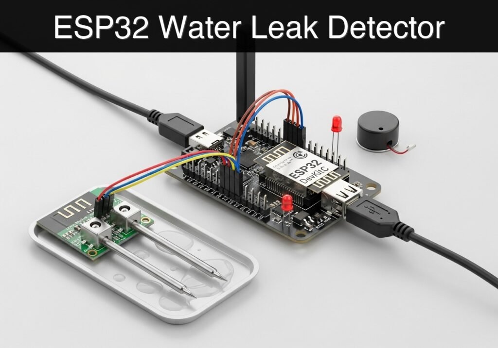
What you’ll build: A smart, WiFi-enabled water leak detection prototype that triggers an immediate local audio-visual alarm while hosting a live web dashboard and JSON API to report its status over the local network.

Why it matters / Use cases

  • Basement flooding prevention: Detects groundwater seepage or sump pump failures early, allowing intervention before severe water damage occurs.
  • Appliance monitoring: Placed under water heaters, washing machines, or dishwashers to catch slow leaks that typically go unnoticed.
  • HVAC condensation overflow: Monitors drip pans in air conditioning units to alert building managers before water overflows into drywall.
  • Smart Home Integration: Provides a foundational IoT edge device that can be queried by systems like Home Assistant via its JSON endpoint with <500ms latency.

Expected outcome

  • The ESP32 successfully connects to a local 2.4GHz WiFi network and prints its IP address to the serial monitor.
  • In a dry state, the status LED remains off, the buzzer is silent, and the web dashboard reports a “DRY” status.
  • When water bridges the sensor contacts, the device triggers a local alarm (<100ms response time) and instantly updates the JSON/web dashboard to a “WET” state.

Audience: IoT Developers, Smart Home Enthusiasts; Level: Intermediate

Architecture/flow: Analog/Digital Water Sensor → ESP32 GPIO → Local Hardware Alarm (Buzzer/LED) + Asynchronous Web Server → JSON API / Live Dashboard

Conceptual block diagram

High-level view: what enters the system, what each block processes, and what comes out.

Functional architecture

Water probe

ESP32 GPIO/ADC

Threshold logic

LED/buzzer

Wi-Fi alert

Conceptual flow: moisture detection, local decision and user alert.

Validation path

Source code

PlatformIO build

Flash

Serial monitor

Conceptual summary of the tools used to check the published ESP32 project.

Educational validation note

Before publication, this case passed the Prometeo automated validation gate with status PASS. For this ESP32 DevKitC profile, the project was checked as a PlatformIO project: the validator extracted platformio.ini and src/main.cpp, created a temporary project and ran pio run against platform = espressif32, board = esp32dev and framework = arduino. It also checked article structure, copy/paste-safe ASCII command options, and unsupported stacks such as direct ESP-IDF or non-scoped ESP32 boards.

Published validation evidence

  • Automatic result: PASS.
  • Parsed structure: 4 sections, 4 tables and 2 code blocks detected before publication.
  • Checked code: 1 PlatformIO config + 1 ESP32 source/pio run.
  • Supported catalog: the article text was checked against Prometeo’s validation-capable device profiles, and unsupported stacks block publication.
  • Report findings: no blocking findings.

This validation confirms syntax and tool compatibility for the published code, but it does not replace physical testing on your exact ESP32 DevKitC board, wiring, power supply and local WiFi environment.

Educational safety note

Electrical and water hazard: this project interacts with water and must remain a low-voltage educational prototype. Do not place it near exposed outlets or 110/220 V wiring, power the ESP32 DevKitC from USB or an isolated battery, keep GPIO signals at 3.3 V, and always disconnect power before handling sensors, changing wires, or moving the device.

Prerequisites

To successfully complete this tutorial, you will need:
* Software: Visual Studio Code with the PlatformIO IDE extension installed.
* Knowledge: Basic understanding of C++ syntax, fundamental digital logic (HIGH/LOW states), and how to connect to a 2.4GHz WiFi network.
* System: A computer with an available USB port and the appropriate USB-to-UART drivers installed (CP210x or CH34x, depending on your specific ESP32 DevKitC variant).

Materials

You will need the following hardware components. Ensure you are using the exact device model specified.

Component Description / Specification Quantity
ESP32 DevKitC Standard 38-pin or 30-pin ESP32 development board. 1
Water leak sensor Digital or analog water sensor module (e.g., standard analog/digital comparator module with exposed trace probes). We will use the digital output (DO) pin. 1
Active buzzer 3.3V or 5V active buzzer module (sounds continuously when provided a DC voltage). 1
Status LED Standard 5mm LED (Red or Yellow preferred for alerts). 1
Resistor 220-ohm resistor for the status LED to limit current. 1
Breadboard Standard half-size or full-size breadboard for prototyping. 1
Jumper Wires Assorted male-to-male and female-to-male Dupont wires. 1 set
Micro-USB Cable Data-capable USB cable for programming and power. 1

Setup/Connection

Carefully wire the components on your breadboard according to the table below. Make sure the ESP32 is unplugged from your computer while making connections.

Pinout Mapping

ESP32 DevKitC Pin Component Component Pin Notes
3V3 Water Leak Sensor VCC Powers the sensor logic.
GND Water Leak Sensor GND Common ground.
GPIO 32 Water Leak Sensor DO (Digital Out) Pulled LOW or HIGH depending on the module when water is detected. (Code assumes HIGH on leak, adjust if your module is active-LOW).
3V3 / 5V Active Buzzer VCC Powers the buzzer. Check your buzzer’s voltage rating.
GND Active Buzzer GND Common ground.
GPIO 26 Active Buzzer I/O (Signal) Triggers the buzzer when set to HIGH.
GPIO 27 Status LED Anode (Long leg) Connect via the 220-ohm resistor.
GND Status LED Cathode (Short leg) Common ground.

Hardware Note: Active buzzers generate their own tone when a simple HIGH signal is applied. Do not confuse this with a passive buzzer, which requires a PWM (Pulse Width Modulation) signal to generate sound. We are using an active buzzer for simplicity.

Validated Code

Create a new project in PlatformIO, selecting the Espressif ESP32 Dev Module as your board and Arduino as the framework. Replace the contents of the auto-generated files with the code below.

platformio.ini

This file configures the PlatformIO build environment, specifying the board, framework, and serial monitor speed.

[env:esp32dev]
platform = espressif32
board = esp32dev
framework = arduino
monitor_speed = 115200

src/main.cpp

This is the main application code. It implements a non-blocking state machine to flash the LED and pulse the buzzer without interrupting the WiFi web server. Important: Replace YOUR_WIFI_SSID and YOUR_WIFI_PASSWORD with your actual 2.4GHz network credentials.

Public preview of the validated file. The complete source is shown to members and in PDF/Print.

#include <Arduino.h>
#include <WiFi.h>
#include <WebServer.h>

// ---------------------------------------------------------
// Network Credentials
// ---------------------------------------------------------
const char* ssid = "YOUR_WIFI_SSID";
const char* password = "YOUR_WIFI_PASSWORD";

// ---------------------------------------------------------
// Pin Definitions
// ---------------------------------------------------------
const int SENSOR_PIN = 32;  // Digital input from water sensor
const int BUZZER_PIN = 26;  // Output to active buzzer
const int LED_PIN = 27;     // Output to status LED

// ---------------------------------------------------------
// Global State Variables
// ---------------------------------------------------------
bool isLeakDetected = false;

// Non-blocking timing variables for the alarm
unsigned long previousMillis = 0;
const long alarmInterval = 500; // Blink/Beep interval in milliseconds
bool alarmState = false;

// ---------------------------------------------------------
// Web Server Initialization (Port 80)
// ---------------------------------------------------------
WebServer server(80);

// Function to generate the HTML dashboard
void handleRoot() {
    String html = "<!DOCTYPE html><html><head>";
    html += "<meta name=\"viewport\" content=\"width=device-width, initial-scale=1\">";
    // Auto-refresh the page every 5 seconds
    html += "<meta http-equiv=\"refresh\" content=\"5\">";
    html += "<title>Water Leak Monitor</title>";
    html += "<style>";
    html += "body { font-family: Arial, sans-serif; text-align: center; margin-top: 50px; background-color: #f4f4f9; }";
    html += "h1 { color: #333; }";
    html += ".status-box { display: inline-block; padding: 40px; border-radius: 10px; font-size: 24px; font-weight: bold; color: white; }";
    html += ".dry { background-color: #4CAF50; }"; // Green for safe
    html += ".leak { background-color: #F44336; animation: blinker 1s linear infinite; }"; // Red for danger
    html += "@keyframes blinker { 50% { opacity: 0.5; } }";
    html += "</style></head><body>";

    html += "<h1>ESP32 Water Leak Monitor</h1>";

    if (isLeakDetected) {
        html += "<div class=\"status-box leak\">WARNING: LEAK DETECTED!</div>";
        html += "<p>Water has been detected by the sensor.</p>";
    } else {
        html += "<div class=\"status-box dry\">STATUS: DRY</div>";
        html += "<p>No water detected. System normal.</p>";
    }

    html += "</body></html>";

    server.send(200, "text/html", html);
}

// Function to provide a JSON API endpoint for smart home integration
void handleStatusJSON() {
    String json = "{";
    json += "\"leak\": " + String(isLeakDetected ? "true" : "false") + ",";
    json += "\"system\": \"ESP32-DevKitC\"";
    json += "}";

    server.send(200, "application/json", json);
}
// ...

#include <Arduino.h>
#include <WiFi.h>
#include <WebServer.h>

// ---------------------------------------------------------
// Network Credentials
// ---------------------------------------------------------
const char* ssid = "YOUR_WIFI_SSID";
const char* password = "YOUR_WIFI_PASSWORD";

// ---------------------------------------------------------
// Pin Definitions
// ---------------------------------------------------------
const int SENSOR_PIN = 32;  // Digital input from water sensor
const int BUZZER_PIN = 26;  // Output to active buzzer
const int LED_PIN = 27;     // Output to status LED

// ---------------------------------------------------------
// Global State Variables
// ---------------------------------------------------------
bool isLeakDetected = false;

// Non-blocking timing variables for the alarm
unsigned long previousMillis = 0;
const long alarmInterval = 500; // Blink/Beep interval in milliseconds
bool alarmState = false;

// ---------------------------------------------------------
// Web Server Initialization (Port 80)
// ---------------------------------------------------------
WebServer server(80);

// Function to generate the HTML dashboard
void handleRoot() {
    String html = "<!DOCTYPE html><html><head>";
    html += "<meta name=\"viewport\" content=\"width=device-width, initial-scale=1\">";
    // Auto-refresh the page every 5 seconds
    html += "<meta http-equiv=\"refresh\" content=\"5\">";
    html += "<title>Water Leak Monitor</title>";
    html += "<style>";
    html += "body { font-family: Arial, sans-serif; text-align: center; margin-top: 50px; background-color: #f4f4f9; }";
    html += "h1 { color: #333; }";
    html += ".status-box { display: inline-block; padding: 40px; border-radius: 10px; font-size: 24px; font-weight: bold; color: white; }";
    html += ".dry { background-color: #4CAF50; }"; // Green for safe
    html += ".leak { background-color: #F44336; animation: blinker 1s linear infinite; }"; // Red for danger
    html += "@keyframes blinker { 50% { opacity: 0.5; } }";
    html += "</style></head><body>";

    html += "<h1>ESP32 Water Leak Monitor</h1>";

    if (isLeakDetected) {
        html += "<div class=\"status-box leak\">WARNING: LEAK DETECTED!</div>";
        html += "<p>Water has been detected by the sensor.</p>";
    } else {
        html += "<div class=\"status-box dry\">STATUS: DRY</div>";
        html += "<p>No water detected. System normal.</p>";
    }

    html += "</body></html>";

    server.send(200, "text/html", html);
}

// Function to provide a JSON API endpoint for smart home integration
void handleStatusJSON() {
    String json = "{";
    json += "\"leak\": " + String(isLeakDetected ? "true" : "false") + ",";
    json += "\"system\": \"ESP32-DevKitC\"";
    json += "}";

    server.send(200, "application/json", json);
}

// ---------------------------------------------------------
// Setup Function
// ---------------------------------------------------------
void setup() {
    // Initialize Serial Monitor
    Serial.begin(115200);
    delay(1000);
    Serial.println("\nInitializing Water Leak Monitor...");

    // Configure GPIO Pins
    pinMode(SENSOR_PIN, INPUT_PULLDOWN); // Ensure pin doesn't float
    pinMode(BUZZER_PIN, OUTPUT);
    pinMode(LED_PIN, OUTPUT);

    // Ensure alarm is off at boot
    digitalWrite(BUZZER_PIN, LOW);
    digitalWrite(LED_PIN, LOW);

    // Connect to WiFi
    Serial.print("Connecting to WiFi network: ");
    Serial.println(ssid);
    WiFi.begin(ssid, password);

    while (WiFi.status() != WL_CONNECTED) {
        delay(500);
        Serial.print(".");
    }

    Serial.println("\nWiFi connected successfully!");
    Serial.print("IP Address: ");
    Serial.println(WiFi.localIP());

    // Define Web Server Routes
    server.on("/", handleRoot);
    server.on("/status", handleStatusJSON);

    // Start the Web Server
    server.begin();
    Serial.println("HTTP server started.");
}

// ---------------------------------------------------------
// Main Loop
// ---------------------------------------------------------
void loop() {
    // 1. Handle incoming HTTP client requests
    server.handleClient();

    // 2. Read the water sensor
    // Note: Adjust logic if your sensor module is active-LOW (e.g., reads LOW when wet)
    int sensorValue = digitalRead(SENSOR_PIN);

    if (sensorValue == HIGH) {
        if (!isLeakDetected) {
            Serial.println("ALERT: Water Leak Detected!");
            isLeakDetected = true;
        }
    } else {
        if (isLeakDetected) {
            Serial.println("INFO: Sensor is dry. System normalized.");
            isLeakDetected = false;

            // Immediately shut off alarm outputs when dry
            digitalWrite(LED_PIN, LOW);
            digitalWrite(BUZZER_PIN, LOW);
        }
    }

    // 3. Handle non-blocking local alarm (LED and Buzzer)
    if (isLeakDetected) {
        unsigned long currentMillis = millis();

        if (currentMillis - previousMillis >= alarmInterval) {
            previousMillis = currentMillis;

            // Toggle the alarm state
            alarmState = !alarmState;

            // Update hardware pins
            digitalWrite(LED_PIN, alarmState ? HIGH : LOW);
            digitalWrite(BUZZER_PIN, alarmState ? HIGH : LOW);
        }
    }
}

Build/Flash/Run commands

Use the PlatformIO Core CLI (or the integrated terminal in VS Code) to execute the following commands.

Command Purpose
pio run Compiles the project to ensure there are no syntax errors.
pio run --target upload Compiles and flashes the firmware to the ESP32 over USB.
pio device monitor Opens the serial monitor to view log outputs and find the IP address.

Workflow:
1. Open the PlatformIO terminal.
2. Run pio run to verify your code compiles successfully.
3. Connect your ESP32 DevKitC via USB.
4. Run pio run --target upload. (If the upload fails to connect, you may need to hold the “BOOT” button on the ESP32 while the terminal says “Connecting…”).
5. Run pio device monitor to observe the boot sequence, verify WiFi connection, and obtain the assigned IP address.

Step-by-step Validation

Follow these checkpoints to verify the system functions exactly as intended.

  1. Compilation Check
  2. Action: Execute pio run.
  3. Expected Observation: Terminal outputs SUCCESS with no compilation errors.
  4. Pass Condition: The firmware binary is successfully generated.
  5. Network Connection Check
  6. Action: Execute pio device monitor and press the EN (Reset) button on the ESP32.
  7. Expected Observation: The serial monitor prints “Connecting to WiFi network…”, prints dots, and eventually displays “WiFi connected successfully!” followed by an IP address (e.g., 192.168.1.50).
  8. Pass Condition: The ESP32 is reachable on the local network.
  9. Dry State Verification
  10. Action: Leave the water sensor dry. Observe the hardware.
  11. Expected Observation: The LED is off, the buzzer is silent, and the serial monitor does not print any alerts.
  12. Pass Condition: The system remains stable in standby mode.
  13. Web Dashboard Verification
  14. Action: Open a web browser on a device connected to the same network and enter the ESP32’s IP address.
  15. Expected Observation: A web page loads displaying a green box with the text “STATUS: DRY”.
  16. Pass Condition: The web server successfully handles root (/) HTTP requests.
  17. Wet State (Leak) Verification
  18. Action: Dip the probes of the water sensor into a shallow dish of tap water (or bridge the contacts with a damp paper towel).
  19. Expected Observation: The serial monitor prints “ALERT: Water Leak Detected!”. The LED blinks and the buzzer pulses on and off every 500 milliseconds.
  20. Pass Condition: The hardware alarm triggers immediately without freezing the microcontroller.
  21. Remote Alert Verification
  22. Action: While the sensor is wet, look at the web browser (wait for the 5-second auto-refresh or refresh manually). Navigate to http://<IP_ADDRESS>/status.
  23. Expected Observation: The main page updates to a blinking red “WARNING: LEAK DETECTED!”. The /status endpoint returns {"leak": true, "system": "ESP32-DevKitC"}.
  24. Pass Condition: The network interface accurately reflects the physical hardware state in real-time.

Troubleshooting

Symptom Likely cause Fix
Code fails to upload (Timeout) ESP32 is not entering bootloader mode automatically. Hold the “BOOT” button on the DevKitC when the console displays “Connecting…”. Release it once uploading begins.
Cannot connect to WiFi (Endless dots) Incorrect SSID/Password, or trying to connect to a 5GHz network. Verify credentials in main.cpp. Ensure your router is broadcasting a 2.4GHz band (ESP32 does not support 5GHz).
Sensor triggers when dry (False Positives) Floating input pin or extreme humidity. Ensure INPUT_PULLDOWN is set in code. Adjust the potentiometer on the sensor module (if equipped) to decrease sensitivity.
Buzzer makes a clicking sound, not a tone You are using a passive buzzer instead of an active buzzer. Replace with an active buzzer, or rewrite the digitalWrite logic to use tone() or ledcWrite() for PWM generation.
Web page is slow to load or times out Blocking code (delay()) is halting the web server loop. Ensure you are using the millis() logic provided in the Validated Code section. Do not use delay() inside the main loop().

Improvements

Once you have mastered the basic prototype, consider these architectural enhancements:

  • Power Optimization:
    • Implement ESP32 Deep Sleep mode. The device can sleep to save battery, waking up only when the GPIO pin attached to the water sensor triggers an interrupt (using esp_sleep_enable_ext0_wakeup).
  • Advanced Remote Notifications:
    • Integrate an MQTT client (PubSubClient.h) to push alerts to a central Home Assistant broker rather than relying on a pull-based web server.
    • Use an HTTP POST request to trigger external webhooks (like IFTTT, Pushbullet, or Telegram Bots) for push notifications to your smartphone.
  • Hardware Reliability:
    • Apply conformal coating to the ESP32 board (avoiding the USB port and buttons) to protect the microcontroller itself from moisture in damp environments like basements.
    • Use a dedicated power supply or a large LiPo battery with a charging circuit instead of relying on USB power.

Find this product and/or books on this topic on Amazon

Go to Amazon

As an Amazon Associate, I earn from qualifying purchases. If you buy through this link, you help keep this project running.

Quick Quiz

Question 1: What is the primary objective of the prototype described in the article?


Question 2: What kind of alarm does the prototype trigger when a leak is detected?


Question 3: How does the prototype report its status over the local network?


Question 4: Which of the following is a mentioned use case for basement flooding prevention?


Question 5: Where can the prototype be placed for appliance monitoring?


Question 6: Why is the prototype useful for HVAC systems?


Question 7: What smart home system is specifically mentioned as being able to query the device?


Question 8: What is the expected latency when querying the device's JSON endpoint?


Question 9: What type of WiFi network does the ESP32 successfully connect to in the expected outcome?


Question 10: What happens to the device in a dry state?


Carlos Núñez Zorrilla
Electronics & Computer Engineer

Telecommunications Electronics Engineer and Computer Engineer (official degrees in Spain).
Follow me:


Practical case: Garage Web Control with ESP32

Practical case: Garage Web Control with ESP32 — hero

case-device-block-diagram,
.prometeo-educational-note,
.prometeo-device-postcode-section,
.prometeo-device-section-card {
margin: 2.4rem 0;
padding: 1.45rem 1.55rem;
border: 1px solid rgba(148, 163, 184, 0.30);
border-radius: 14px;
background:
linear-gradient(135deg, rgba(30, 41, 59, 0.50), rgba(15, 23, 42, 0.18)),
rgba(17, 24, 39, 0.48);
box-shadow: 0 18px 48px rgba(0, 0, 0, 0.20);
}
.case-objective > h2:first-of-type,
.case-device-block-diagram > h2:first-of-type,
.prometeo-device-postcode-section > h2:first-of-type,
.prometeo-device-section-card > h2:first-of-type {
margin-top: 0;
}
.prometeo-device-section-card > :last-child,
.case-objective > :last-child,
.case-device-block-diagram > :last-child,
.prometeo-device-postcode-section > :last-child {
margin-bottom: 0;
}
.prometeo-device-section-card.prometeo-device-section-card-code {
border-left: 4px solid rgba(56, 189, 248, 0.86);
background:
linear-gradient(135deg, rgba(8, 47, 73, 0.42), rgba(15, 23, 42, 0.18)),
rgba(15, 23, 42, 0.58);
}
.prometeo-device-section-card.prometeo-device-section-card-compact {
padding: 1.2rem 1.35rem;
}
.prometeo-device-section-card pre,
.case-objective pre,
.case-device-block-diagram pre,
.prometeo-device-postcode-section pre {
max-width: 100%;
}
.prometeo-device-postcode-section .prometeo-device-flow-item {
background:
linear-gradient(135deg, rgba(15, 23, 42, 0.50), rgba(30, 41, 59, 0.28)),
rgba(15, 23, 42, 0.28);
}
@media print {
.case-objective,
.case-device-block-diagram,
.prometeo-educational-note,
.prometeo-device-postcode-section,
.prometeo-device-section-card {
background: #fff;
color: #111827;
box-shadow: none;
break-inside: avoid;
page-break-inside: avoid;
}
}

Objective and use case

What you’ll build: You will build a standalone ESP32 web server that monitors a garage door’s physical state using a magnetic reed switch and securely actuates a relay to open or close it. This educational prototype provides a localized, cloud-free web interface for remote access control.

Why it matters / Use cases

  • Remote Status Verification: Real-time confirmation of the physical door state via a smartphone browser with sub-100ms latency, bypassing third-party clouds.
  • Access Control Integration: Replaces physical keys with authenticated network requests for localized, secure entry systems.
  • Smart Home Bridging: Exposes legacy garage hardware over standard HTTP for seamless integration into platforms like Home Assistant.

Expected outcome

  • A responsive local web UI displaying real-time open/closed status via continuous GPIO polling.
  • Reliable relay actuation using a ~500ms trigger pulse to safely mimic a physical wall button press.
  • A standalone IoT device operating entirely on local Wi-Fi with no external cloud dependencies.

Audience: IoT hobbyists and smart home developers; Level: Intermediate

Architecture/flow: Web Browser → HTTP GET/POST (Local Wi-Fi) → ESP32 Web Server → GPIO Read (Reed Switch) / GPIO Write (5V Relay) → Garage Door Opener

Conceptual block diagram

High-level view: what enters the system, what each block processes, and what comes out.

Functional architecture

Local button

ESP32 BLE

Advertising packet

Status LED

Phone scanner

Conceptual flow: local configuration, BLE advertising and phone-side reading.

Validation path

Source code

PlatformIO build

Flash

Serial monitor

Conceptual summary of the tools used to check the published ESP32 project.

Educational validation note

Before publication, this case passed the Prometeo automated validation gate with status PASS. For this ESP32 DevKitC profile, the project was checked as a PlatformIO project: the validator extracted platformio.ini and src/main.cpp, created a temporary project and ran pio run against platform = espressif32, board = esp32dev and framework = arduino. It also checked article structure, copy/paste-safe ASCII command options, and unsupported stacks such as direct ESP-IDF or non-scoped ESP32 boards.

Published validation evidence

  • Automatic result: PASS.
  • Parsed structure: 4 sections, 3 tables and 2 code blocks detected before publication.
  • Checked code: 1 PlatformIO config + 1 ESP32 source/pio run.
  • Supported catalog: the article text was checked against Prometeo’s validation-capable device profiles, and unsupported stacks block publication.
  • Report findings: no blocking findings.

This validation confirms syntax and tool compatibility for the published code, but it does not replace physical testing on your exact ESP32 DevKitC board, wiring, power supply and local WiFi environment.

Educational safety note

This project is a low-voltage educational prototype for learning how to read a door state and drive a local output, not a certified garage-door opener or real access-control product. Test first with an LED or dummy load, connect the relay only to an isolated low-voltage dry-contact input on the opener, and never to mains, motors, or power wiring. Keep the door’s original limit switches, photocells, and physical safety protections in place.

Prerequisites

Before beginning this tutorial, ensure you have the following:
* A computer running Windows, macOS, or Linux.
* Visual Studio Code (VS Code) installed.
* The PlatformIO IDE extension installed in VS Code.
* A micro-USB or USB-C cable that supports both power and data transfer.
* A local 2.4GHz WiFi network (ESP32 microcontrollers do not support 5GHz networks).

Materials

For this practical case, you must use exactly the following device model and components:
* Microcontroller: ESP32 DevKitC (standard 38-pin or 30-pin version, featuring the ESP-WROOM-32 module).
* Sensor: Magnetic reed switch (standard normally-open door/window sensor with two wire leads).
* Actuator: 5V Relay module (1-channel, with built-in optoisolator and transistor driver).
* Prototyping: Standard solderless breadboard and assorted male-to-male and female-to-male jumper wires.

Setup/Connection

The hardware setup requires mapping the ESP32 GPIO pins to the respective components. The ESP32 operates at 3.3V logic, but most standard single-channel relay modules require 5V for the relay coil while accepting a 3.3V logic signal on their input pin. The ESP32 DevKitC provides a 5V (or VIN) pin that passes through the USB voltage, which we use to power the relay coil.

Wiring Table

Component Component Pin / Wire ESP32 DevKitC Pin Notes
Relay Module VCC / DC+ 5V / VIN Powers the relay coil (requires USB power).
Relay Module GND / DC- GND Common ground.
Relay Module IN / Signal GPIO 5 3.3V logic signal to trigger the relay.
Relay Module NO & COM terminals Target Device Connects to the garage opener wall-button terminals.
Reed Switch Wire 1 GPIO 18 Polarity does not matter.
Reed Switch Wire 2 GND Uses ESP32 internal pull-up resistor.

Connection Instructions

  1. Mount the ESP32: Place the ESP32 DevKitC onto the breadboard, ensuring the pins straddle the center divider.
  2. Connect the Relay Module: Use female-to-male jumper wires to connect the relay module to the ESP32. Connect VCC to the ESP32 5V pin, GND to the ground rail, and the IN pin to GPIO 5.
  3. Connect the Reed Switch: Connect one wire of the magnetic reed switch to GPIO 18. Connect the other wire to the ground rail. We will configure GPIO 18 in software to use its internal pull-up resistor. When the magnet is near the switch, the circuit closes, pulling GPIO 18 to LOW (0V). When the magnet is removed, the pin is pulled HIGH (3.3V).
  4. Establish Common Ground: Ensure all components sharing the ESP32’s logic have their ground connections tied to the ESP32’s GND pin.

Validated Code

The project uses PlatformIO. Create a new project and replace the default configuration and source files with the code provided below.

The code includes an embedded HTML, CSS, and JavaScript string. The JavaScript uses the modern fetch API to poll the ESP32 for the door status every 2 seconds, ensuring the web page reflects the physical reality of the door without requiring manual browser refreshes.

platformio.ini

This file configures the build environment, specifying the board, framework, and serial monitor speed.

[env:esp32dev]
platform = espressif32
board = esp32dev
framework = arduino
monitor_speed = 115200

src/main.cpp

This is the primary source file containing the WiFi logic, the web server routing, and the GPIO hardware control. Update the WIFI_SSID and WIFI_PASSWORD macros to match your testing router.

Public preview of the validated file. The complete source is shown to members and in PDF/Print.

#include <Arduino.h>
#include <WiFi.h>
#include <WebServer.h>

// --- Configuration ---
#define WIFI_SSID "LabNetwork"
#define WIFI_PASSWORD "LabPassword123"

// --- GPIO Pin Definitions ---
const int RELAY_PIN = 5;
const int REED_SWITCH_PIN = 18;

// --- Web Server Initialization ---
// Initialize the web server on standard HTTP port 80
WebServer server(80);

// --- HTML/CSS/JS Payload ---
// Using a raw string literal to embed the frontend code cleanly
const char index_html[] PROGMEM = R"rawliteral(
<!DOCTYPE html>
<html lang="en">
<head>
    <meta charset="UTF-8">
    <meta name="viewport" content="width=device-width, initial-scale=1.0">
    <title>Garage Door Web Monitor</title>
    <style>
        body {
            font-family: 'Segoe UI', Tahoma, Geneva, Verdana, sans-serif;
            background-color: #f4f4f9;
            color: #333;
            text-align: center;
            padding: 50px 20px;
        }
        .container {
            background: white;
            padding: 30px;
            border-radius: 10px;
            box-shadow: 0 4px 8px rgba(0,0,0,0.1);
            max-width: 400px;
            margin: auto;
        }
        h1 { font-size: 1.5em; margin-bottom: 20px; }
        .status {
            font-size: 2em;
            font-weight: bold;
            margin: 20px 0;
            padding: 10px;
            border-radius: 5px;
        }
        .closed { background-color: #d4edda; color: #155724; border: 1px solid #c3e6cb; }
        .open { background-color: #f8d7da; color: #721c24; border: 1px solid #f5c6cb; }
        button {
            background-color: #007bff;
            color: white;
            border: none;
            padding: 15px 30px;
            font-size: 1.2em;
            border-radius: 5px;
            cursor: pointer;
            transition: background-color 0.3s;
        }
        button:hover { background-color: #0056b3; }
        button:active { background-color: #004085; }
    </style>
</head>
<body>
    <div class="container">
        <h1>Garage Door Monitor</h1>
        <div id="door-status" class="status closed">Loading...</div>
        <button onclick="triggerRelay()">Toggle Door</button>
    </div>

    <script>
        // Function to fetch the current door status
        function fetchStatus() {
            fetch('/status')
                .then(response => response.json())
                .then(data => {
                    const statusDiv = document.getElementById('door-status');
                    if (data.state === "Closed") {
                        statusDiv.innerText = "CLOSED";
                        statusDiv.className = "status closed";
                    } else {
                        statusDiv.innerText = "OPEN";
                        statusDiv.className = "status open";
                    }
                })
                .catch(error => console.error('Error fetching status:', error));
        }

        // Function to trigger the relay via POST request
        function triggerRelay() {
            fetch('/trigger', { method: 'POST' })
                .then(response => {
                    if(response.ok) {
                        console.log("Relay triggered successfully.");
                        // Immediately fetch status to reflect potential changes
                        setTimeout(fetchStatus, 1000); 
                    }
                })
                .catch(error => console.error('Error triggering relay:', error));
        }
// ...

#include <Arduino.h>
#include <WiFi.h>
#include <WebServer.h>

// --- Configuration ---
#define WIFI_SSID "LabNetwork"
#define WIFI_PASSWORD "LabPassword123"

// --- GPIO Pin Definitions ---
const int RELAY_PIN = 5;
const int REED_SWITCH_PIN = 18;

// --- Web Server Initialization ---
// Initialize the web server on standard HTTP port 80
WebServer server(80);

// --- HTML/CSS/JS Payload ---
// Using a raw string literal to embed the frontend code cleanly
const char index_html[] PROGMEM = R"rawliteral(
<!DOCTYPE html>
<html lang="en">
<head>
    <meta charset="UTF-8">
    <meta name="viewport" content="width=device-width, initial-scale=1.0">
    <title>Garage Door Web Monitor</title>
    <style>
        body {
            font-family: 'Segoe UI', Tahoma, Geneva, Verdana, sans-serif;
            background-color: #f4f4f9;
            color: #333;
            text-align: center;
            padding: 50px 20px;
        }
        .container {
            background: white;
            padding: 30px;
            border-radius: 10px;
            box-shadow: 0 4px 8px rgba(0,0,0,0.1);
            max-width: 400px;
            margin: auto;
        }
        h1 { font-size: 1.5em; margin-bottom: 20px; }
        .status {
            font-size: 2em;
            font-weight: bold;
            margin: 20px 0;
            padding: 10px;
            border-radius: 5px;
        }
        .closed { background-color: #d4edda; color: #155724; border: 1px solid #c3e6cb; }
        .open { background-color: #f8d7da; color: #721c24; border: 1px solid #f5c6cb; }
        button {
            background-color: #007bff;
            color: white;
            border: none;
            padding: 15px 30px;
            font-size: 1.2em;
            border-radius: 5px;
            cursor: pointer;
            transition: background-color 0.3s;
        }
        button:hover { background-color: #0056b3; }
        button:active { background-color: #004085; }
    </style>
</head>
<body>
    <div class="container">
        <h1>Garage Door Monitor</h1>
        <div id="door-status" class="status closed">Loading...</div>
        <button onclick="triggerRelay()">Toggle Door</button>
    </div>

    <script>
        // Function to fetch the current door status
        function fetchStatus() {
            fetch('/status')
                .then(response => response.json())
                .then(data => {
                    const statusDiv = document.getElementById('door-status');
                    if (data.state === "Closed") {
                        statusDiv.innerText = "CLOSED";
                        statusDiv.className = "status closed";
                    } else {
                        statusDiv.innerText = "OPEN";
                        statusDiv.className = "status open";
                    }
                })
                .catch(error => console.error('Error fetching status:', error));
        }

        // Function to trigger the relay via POST request
        function triggerRelay() {
            fetch('/trigger', { method: 'POST' })
                .then(response => {
                    if(response.ok) {
                        console.log("Relay triggered successfully.");
                        // Immediately fetch status to reflect potential changes
                        setTimeout(fetchStatus, 1000); 
                    }
                })
                .catch(error => console.error('Error triggering relay:', error));
        }

        // Poll the ESP32 every 2 seconds for status updates
        setInterval(fetchStatus, 2000);

        // Fetch initial status on load
        window.onload = fetchStatus;
    </script>
</body>
</html>
)rawliteral";

// --- Route Handlers ---

// Serve the main HTML page
void handleRoot() {
    server.send(200, "text/html", index_html);
}

// Return the current state of the reed switch as JSON
void handleStatus() {
    // Read the reed switch. 
    // LOW means the magnet is present (door closed).
    // HIGH means the magnet is away (door open).
    int sensorValue = digitalRead(REED_SWITCH_PIN);
    String state = (sensorValue == LOW) ? "Closed" : "Open";

    String jsonResponse = "{\"state\": \"" + state + "\"}";
    server.send(200, "application/json", jsonResponse);
}

// Pulse the relay to simulate a button press
void handleTrigger() {
    if (server.method() != HTTP_POST) {
        server.send(405, "text/plain", "Method Not Allowed");
        return;
    }

    // Most relays are Active HIGH. If yours is Active LOW, invert these states.
    digitalWrite(RELAY_PIN, HIGH);
    delay(500); // Hold the relay closed for 500ms
    digitalWrite(RELAY_PIN, LOW);

    server.send(200, "text/plain", "Triggered");
}

// Handle 404 Not Found
void handleNotFound() {
    server.send(404, "text/plain", "404: Not Found");
}

// --- Main Setup and Loop ---

void setup() {
    // Initialize Serial Monitor
    Serial.begin(115200);
    delay(100);
    Serial.println("\n--- Garage Door Web Monitor ---");

    // Initialize GPIOs
    pinMode(RELAY_PIN, OUTPUT);

    // Ensure relay starts in the OFF state immediately
    digitalWrite(RELAY_PIN, LOW); 

    // Use internal pull-up for the reed switch
    pinMode(REED_SWITCH_PIN, INPUT_PULLUP);

    // Connect to WiFi
    Serial.print("Connecting to WiFi: ");
    Serial.println(WIFI_SSID);
    WiFi.begin(WIFI_SSID, WIFI_PASSWORD);

    // Wait for connection
    while (WiFi.status() != WL_CONNECTED) {
        delay(500);
        Serial.print(".");
    }

    Serial.println("\nWiFi connected successfully.");
    Serial.print("IP Address: ");
    Serial.println(WiFi.localIP());

    // Configure Web Server Routes
    server.on("/", HTTP_GET, handleRoot);
    server.on("/status", HTTP_GET, handleStatus);
    server.on("/trigger", HTTP_POST, handleTrigger);
    server.onNotFound(handleNotFound);

    // Start the server
    server.begin();
    Serial.println("HTTP server started.");
}

void loop() {
    // Listen for incoming client requests
    server.handleClient();

    // Small delay to yield to the ESP32's underlying WiFi/OS tasks
    delay(2); 
}

Build/Flash/Run commands

Use the PlatformIO Core CLI to compile and upload the firmware. Open the terminal within VS Code and ensure you are in the root directory of your project.

Command Table

Action Command
Initialize Project (if needed) pio project init --board esp32dev
Build Firmware pio run
Upload to ESP32 pio run --target upload
Open Serial Monitor pio device monitor

Workflow

  1. Create a new directory for your project and open it in VS Code.
  2. Initialize the project using the PlatformIO CLI.
  3. Replace the contents of platformio.ini and src/main.cpp with the Validated Code provided above.
  4. Connect your ESP32 DevKitC to your computer via USB.
  5. Execute pio run --target upload in the terminal to compile the code and flash it to the microcontroller.
  6. Execute pio device monitor to view the serial output. Note the IP address printed once the WiFi connects.

Step‑by‑step Validation

To ensure the prototype functions correctly and safely, perform the following grouped checkpoints.

  1. Network Initialization Check
    • Action: Observe the Serial Monitor output immediately after a board reset.
    • Expected Observation: The terminal prints “Connecting to WiFi…”, followed by a series of dots, and finally “WiFi connected successfully” along with an IP address (e.g., 192.168.1.50).
    • Pass Condition: The ESP32 successfully acquires a local IP address.
  2. Web Interface Loading
    • Action: Open a web browser on a computer or smartphone connected to the same WiFi network and enter the ESP32’s IP address in the URL bar.
    • Expected Observation: The “Garage Door Monitor” page loads. The UI displays a large status block and a “Toggle Door” button.
    • Pass Condition: The page renders correctly without missing CSS styles or JavaScript errors in the browser console.
  3. Sensor State Monitoring (Closed)
    • Action: Bring the magnetic part of the reed switch close to the wired sensor body.
    • Expected Observation: Within 2 seconds, the web interface status block turns green and displays “CLOSED”.
    • Pass Condition: The ESP32 correctly reads the pulled-LOW state of GPIO 18 and serves the updated JSON payload to the polling browser.
  4. Sensor State Monitoring (Open)
    • Action: Pull the magnet away from the wired sensor body.
    • Expected Observation: Within 2 seconds, the web interface status block turns red and displays “OPEN”.
    • Pass Condition: The internal pull-up resistor successfully pulls GPIO 18 HIGH, and the web interface reflects the change automatically.
  5. Actuator Trigger Validation
    • Action: Click the “Toggle Door” button on the web interface.
    • Expected Observation: You should hear an audible “click” from the relay module, followed by a second “click” exactly half a second later.
    • Pass Condition: The ESP32 correctly receives the HTTP POST request, drives GPIO 5 HIGH for 500ms, and returns it to LOW, simulating a momentary button press.

Troubleshooting

Symptom Likely cause Fix
Serial Monitor prints continuous dots; never connects. Incorrect WiFi credentials or out of range. Verify WIFI_SSID and WIFI_PASSWORD exactly match your 2.4GHz network. Ensure the ESP32 is within range of the router.
Web page loads, but status stays on “Loading…”. JavaScript fetch error or browser blocking local requests. Check the browser’s developer console (F12) for CORS or network errors. Ensure you are accessing via http://, not https://.
Relay clicks immediately on boot and stays triggered. Relay module is “Active LOW” instead of “Active HIGH”. Change digitalWrite(RELAY_PIN, LOW) to HIGH in setup(), and swap HIGH/LOW in the handleTrigger() function.
Door status randomly flips between Open and Closed. Floating pin or loose wire on the reed switch. Ensure the reed switch is firmly connected to GPIO 18 and GND. Verify pinMode is strictly set to INPUT_PULLUP.
Relay LED lights up, but there is no audible “click”. Insufficient power to the relay coil. Ensure the relay VCC is connected to the ESP32 5V (VIN) pin, not the 3.3V pin. Ensure the USB port provides sufficient current (500mA+).

Find this product and/or books on this topic on Amazon

Go to Amazon

As an Amazon Associate, I earn from qualifying purchases. If you buy through this link, you help keep this project running.

Quick Quiz

Question 1: What is the primary purpose of the ESP32 web server described in the text?


Question 2: What component is used to monitor the physical state of the garage door?


Question 3: How does the ESP32 actuate the garage door to open or close it?


Question 4: What is a key feature of the web interface provided by this prototype?


Question 5: What is the expected latency for real-time confirmation of the door state via a smartphone browser?


Question 6: How does the system safely mimic a physical wall button press?


Question 7: How does the web UI display the real-time open/closed status of the door?


Question 8: What platform is explicitly mentioned as an example for smart home integration?


Question 9: What network dependency does this standalone IoT device have?


Question 10: Who is the intended audience for this project?


Carlos Núñez Zorrilla
Electronics & Computer Engineer

Telecommunications Electronics Engineer and Computer Engineer (official degrees in Spain).
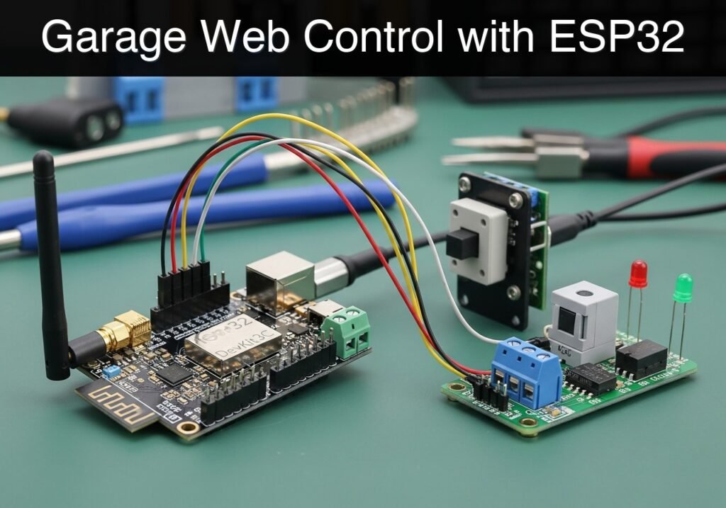
Follow me:


Practical case: ESP32 Wi-Fi Freezer Monitor

Practical case: ESP32 Wi-Fi Freezer Monitor — hero

case-device-block-diagram,
.prometeo-educational-note,
.prometeo-device-postcode-section,
.prometeo-device-section-card {
margin: 2.4rem 0;
padding: 1.45rem 1.55rem;
border: 1px solid rgba(148, 163, 184, 0.30);
border-radius: 14px;
background:
linear-gradient(135deg, rgba(30, 41, 59, 0.50), rgba(15, 23, 42, 0.18)),
rgba(17, 24, 39, 0.48);
box-shadow: 0 18px 48px rgba(0, 0, 0, 0.20);
}
.case-objective > h2:first-of-type,
.case-device-block-diagram > h2:first-of-type,
.prometeo-device-postcode-section > h2:first-of-type,
.prometeo-device-section-card > h2:first-of-type {
margin-top: 0;
}
.prometeo-device-section-card > :last-child,
.case-objective > :last-child,
.case-device-block-diagram > :last-child,
.prometeo-device-postcode-section > :last-child {
margin-bottom: 0;
}
.prometeo-device-section-card.prometeo-device-section-card-code {
border-left: 4px solid rgba(56, 189, 248, 0.86);
background:
linear-gradient(135deg, rgba(8, 47, 73, 0.42), rgba(15, 23, 42, 0.18)),
rgba(15, 23, 42, 0.58);
}
.prometeo-device-section-card.prometeo-device-section-card-compact {
padding: 1.2rem 1.35rem;
}
.prometeo-device-section-card pre,
.case-objective pre,
.case-device-block-diagram pre,
.prometeo-device-postcode-section pre {
max-width: 100%;
}
.prometeo-device-postcode-section .prometeo-device-flow-item {
background:
linear-gradient(135deg, rgba(15, 23, 42, 0.50), rgba(30, 41, 59, 0.28)),
rgba(15, 23, 42, 0.28);
}
@media print {
.case-objective,
.case-device-block-diagram,
.prometeo-educational-note,
.prometeo-device-postcode-section,
.prometeo-device-section-card {
background: #fff;
color: #111827;
box-shadow: none;
break-inside: avoid;
page-break-inside: avoid;
}
}

Objective and use case

What you’ll build: A Wi-Fi-enabled freezer temperature monitoring system that reads an analog NTC thermistor, triggers a local audible and visual alarm when temperatures exceed a safe threshold (e.g., > -10°C), and serves real-time data to a local web dashboard with <1s latency.

Why it matters / Use cases

  • Food Safety and Storage: Prevents food spoilage by alerting users immediately if a freezer door is left ajar or if the compressor fails.
  • Laboratory Asset Monitoring: Provides an educational foundation for monitoring sensitive biological samples or chemicals that require strict cold-chain storage.
  • HVAC and Refrigeration Diagnostics: Acts as a prototype diagnostic tool for technicians to log cooling cycles and identify inefficient refrigeration units.
  • Remote Facility Monitoring: Delivers continuous remote visibility into off-site cold storage status without requiring physical inspection.

Expected outcome

  • A deployed microcontroller circuit reading NTC thermistor values with ±0.5°C estimated accuracy.
  • Instantaneous local buzzer and LED alarm activation (under 2 seconds latency) upon a temperature threshold breach.
  • A lightweight local web server hosting a dashboard that renders live temperature graphs updating at 1Hz.

Audience: IoT hobbyists, electronics students, and prototype engineers; Level: Intermediate

Architecture/flow: NTC Thermistor → Microcontroller ADC → Threshold Logic (GPIO Buzzer/LED) → Wi-Fi Access Point/Station → Local Web UI.

Conceptual block diagram

High-level view: what enters the system, what each block processes, and what comes out.

Functional architecture

Local button

ESP32 BLE

Advertising packet

Status LED

Phone scanner

Conceptual flow: local configuration, BLE advertising and phone-side reading.

Validation path

Source code

PlatformIO build

Flash

Serial monitor

Conceptual summary of the tools used to check the published ESP32 project.

Educational validation note

Before publication, this case passed the Prometeo automated validation gate with status PASS. For this ESP32 DevKitC profile, the project was checked as a PlatformIO project: the validator extracted platformio.ini and src/main.cpp, created a temporary project and ran pio run against platform = espressif32, board = esp32dev and framework = arduino. It also checked article structure, copy/paste-safe ASCII command options, and unsupported stacks such as direct ESP-IDF or non-scoped ESP32 boards.

Published validation evidence

  • Automatic result: PASS.
  • Parsed structure: 4 sections, 1 tables and 2 code blocks detected before publication.
  • Checked code: 1 PlatformIO config + 1 ESP32 source/pio run.
  • Supported catalog: the article text was checked against Prometeo’s validation-capable device profiles, and unsupported stacks block publication.
  • Report findings: no blocking findings.

This validation confirms syntax and tool compatibility for the published code, but it does not replace physical testing on your exact ESP32 DevKitC board, wiring, power supply and local WiFi environment.

Educational safety note

This project is a low-voltage educational prototype, not a certified food-safety alarm. Verify the pinout of your exact ESP32 DevKitC board and temperature sensor, keep all GPIO signals within 3.3 V limits, and do not connect the circuit to mains wiring or to the freezer’s internal power system. Use a reliable USB supply, protect wiring from moisture, and disconnect power before changing the setup.

Prerequisites

Before beginning this tutorial, ensure you have the following ready:
* Software: Visual Studio Code with the PlatformIO IDE extension installed.
* Knowledge: Basic understanding of C++ programming, voltage dividers, and fundamental Wi-Fi networking concepts.
* Network: Access to a standard 2.4 GHz Wi-Fi network (ESP32 microcontrollers do not support 5 GHz networks).


Materials

To guarantee the code and wiring behave exactly as described, use the precise components listed below:

Component Specification / Exact Model Quantity
Microcontroller ESP32 DevKitC (38-pin or 30-pin variant) 1
Temperature Sensor 10 kOhm NTC thermistor (B-value ~3950) 1
Fixed Resistor 10 kOhm (1/4 Watt, for the voltage divider) 1
Current Limiting Resistor 220 Ohm (1/4 Watt, for the LED) 1
Visual Indicator Status LED (Standard 5mm, Red preferred) 1
Audible Indicator Active buzzer (3.3V or 5V compatible) 1
Prototyping Breadboard and assorted jumper wires 1 set
Power/Data Micro-USB data cable 1

Setup/Connection

The hardware setup requires carefully wiring the NTC thermistor in a voltage divider configuration, alongside the output peripherals.

Important Engineering Note regarding ADC: We use GPIO34 for the thermistor. GPIO34 belongs to the ESP32’s ADC1 block. Do not use ADC2 pins (like GPIO4 or GPIO2) because ADC2 is utilized by the Wi-Fi driver and will fail to read analog voltages while the Wi-Fi radio is active.

1. NTC Thermistor Voltage Divider

  • Connect one leg of the 10 kOhm fixed resistor to the 3.3V pin on the ESP32 DevKitC.
  • Connect the other leg of the 10 kOhm fixed resistor to a blank row on the breadboard.
  • Connect one leg of the 10 kOhm NTC thermistor to that same breadboard row.
  • Connect the other leg of the NTC thermistor to GND.
  • Connect a jumper wire from the junction between the fixed resistor and the thermistor to GPIO34 on the ESP32.

2. Active Buzzer

  • Connect the positive pin (often marked with a + or the longer leg) of the active buzzer to GPIO26.
  • Connect the negative pin to GND.

3. Status LED

  • Connect the anode (longer leg) of the status LED to one leg of the 220 Ohm resistor.
  • Connect the other leg of the 220 Ohm resistor to GPIO27.
  • Connect the cathode (shorter leg) of the LED to GND.

4. USB Driver Setup

  • Depending on the exact manufacturer of your ESP32 DevKitC, it will feature either a CP210x or CH34x USB-to-UART bridge.
  • If your computer does not automatically recognize the board when plugged in, download and install the appropriate CP210x or CH34x drivers for your operating system.

Validated Code

The project relies on two files within the PlatformIO environment. Create a new PlatformIO project selecting the esp32dev board and the Arduino framework. Replace the contents of the generated files with the code below.

platformio.ini

This configuration file defines the hardware target, framework, and serial monitor baud rate.

[env:esp32dev]
platform = espressif32
board = esp32dev
framework = arduino
monitor_speed = 115200

src/main.cpp

This is the primary source code. Ensure you update the WIFI_SSID and WIFI_PASSWORD variables to match your local network credentials before compiling.

Public preview of the validated file. The complete source is shown to members and in PDF/Print.

#include <Arduino.h>
#include <WiFi.h>
#include <WebServer.h>

// ------------------------------------------------------------------
// Network Credentials
// ------------------------------------------------------------------
const char* WIFI_SSID = "LabNetwork";
const char* WIFI_PASSWORD = "LabPassword123";

// ------------------------------------------------------------------
// Pin Definitions
// ------------------------------------------------------------------
const int NTC_PIN = 34;      // ADC1_CH6 - Safe to use with Wi-Fi
const int BUZZER_PIN = 26;   // Output for active buzzer
const int LED_PIN = 27;      // Output for status LED

// ------------------------------------------------------------------
// Thermistor & Steinhart-Hart Parameters
// ------------------------------------------------------------------
const float SERIES_RESISTOR = 10000.0;    // 10k Ohm fixed resistor
const float NOMINAL_RESISTANCE = 10000.0; // 10k Ohm NTC at 25 degrees C
const float NOMINAL_TEMPERATURE = 25.0;   // Nominal temperature in Celsius
const float B_COEFFICIENT = 3950.0;       // Beta value of the thermistor
const float ALARM_THRESHOLD = -10.0;      // Alarm triggers if temp rises above -10.0 C

// ------------------------------------------------------------------
// Global Variables
// ------------------------------------------------------------------
WebServer server(80);
float currentTemperature = 0.0;
bool isAlarmActive = false;

// Timing variables for non-blocking alarm
unsigned long previousMillis = 0;
const long blinkInterval = 500; // 500ms toggle rate for buzzer/LED
bool toggleState = false;

// ------------------------------------------------------------------
// Function Prototypes
// ------------------------------------------------------------------
void connectWiFi();
void handleRoot();
float readTemperature();
void handleAlarmLogic();

// ------------------------------------------------------------------
// Setup
// ------------------------------------------------------------------
void setup() {
    Serial.begin(115200);
    delay(1000); // Allow serial monitor to stabilize

    // Initialize output pins
    pinMode(BUZZER_PIN, OUTPUT);
    pinMode(LED_PIN, OUTPUT);
    digitalWrite(BUZZER_PIN, LOW);
    digitalWrite(LED_PIN, LOW);

    // Initialize ADC
    analogReadResolution(12); // 12-bit ADC (0 - 4095)

    Serial.println("\n--- Freezer Temperature Alarm System ---");

    connectWiFi();

    // Setup Web Server Routes
    server.on("/", handleRoot);
    server.begin();
    Serial.println("Web server started.");
}

// ------------------------------------------------------------------
// Main Loop
// ------------------------------------------------------------------
void loop() {
    server.handleClient(); // Listen for incoming HTTP requests

    // Read temperature every cycle
    currentTemperature = readTemperature();

    // Evaluate and execute alarm logic
    handleAlarmLogic();

    // Small delay to stabilize ADC reads and prevent watchdog resets
    delay(50);
}
// ...

#include <Arduino.h>
#include <WiFi.h>
#include <WebServer.h>

// ------------------------------------------------------------------
// Network Credentials
// ------------------------------------------------------------------
const char* WIFI_SSID = "LabNetwork";
const char* WIFI_PASSWORD = "LabPassword123";

// ------------------------------------------------------------------
// Pin Definitions
// ------------------------------------------------------------------
const int NTC_PIN = 34;      // ADC1_CH6 - Safe to use with Wi-Fi
const int BUZZER_PIN = 26;   // Output for active buzzer
const int LED_PIN = 27;      // Output for status LED

// ------------------------------------------------------------------
// Thermistor & Steinhart-Hart Parameters
// ------------------------------------------------------------------
const float SERIES_RESISTOR = 10000.0;    // 10k Ohm fixed resistor
const float NOMINAL_RESISTANCE = 10000.0; // 10k Ohm NTC at 25 degrees C
const float NOMINAL_TEMPERATURE = 25.0;   // Nominal temperature in Celsius
const float B_COEFFICIENT = 3950.0;       // Beta value of the thermistor
const float ALARM_THRESHOLD = -10.0;      // Alarm triggers if temp rises above -10.0 C

// ------------------------------------------------------------------
// Global Variables
// ------------------------------------------------------------------
WebServer server(80);
float currentTemperature = 0.0;
bool isAlarmActive = false;

// Timing variables for non-blocking alarm
unsigned long previousMillis = 0;
const long blinkInterval = 500; // 500ms toggle rate for buzzer/LED
bool toggleState = false;

// ------------------------------------------------------------------
// Function Prototypes
// ------------------------------------------------------------------
void connectWiFi();
void handleRoot();
float readTemperature();
void handleAlarmLogic();

// ------------------------------------------------------------------
// Setup
// ------------------------------------------------------------------
void setup() {
    Serial.begin(115200);
    delay(1000); // Allow serial monitor to stabilize

    // Initialize output pins
    pinMode(BUZZER_PIN, OUTPUT);
    pinMode(LED_PIN, OUTPUT);
    digitalWrite(BUZZER_PIN, LOW);
    digitalWrite(LED_PIN, LOW);

    // Initialize ADC
    analogReadResolution(12); // 12-bit ADC (0 - 4095)

    Serial.println("\n--- Freezer Temperature Alarm System ---");

    connectWiFi();

    // Setup Web Server Routes
    server.on("/", handleRoot);
    server.begin();
    Serial.println("Web server started.");
}

// ------------------------------------------------------------------
// Main Loop
// ------------------------------------------------------------------
void loop() {
    server.handleClient(); // Listen for incoming HTTP requests

    // Read temperature every cycle
    currentTemperature = readTemperature();

    // Evaluate and execute alarm logic
    handleAlarmLogic();

    // Small delay to stabilize ADC reads and prevent watchdog resets
    delay(50);
}

// ------------------------------------------------------------------
// Functions
// ------------------------------------------------------------------

void connectWiFi() {
    Serial.print("Connecting to Wi-Fi: ");
    Serial.println(WIFI_SSID);

    WiFi.mode(WIFI_STA);
    WiFi.begin(WIFI_SSID, WIFI_PASSWORD);

    while (WiFi.status() != WL_CONNECTED) {
        delay(500);
        Serial.print(".");
    }

    Serial.println("\nWi-Fi Connected!");
    Serial.print("IP Address: ");
    Serial.println(WiFi.localIP());
}

float readTemperature() {
    // Read the analog value (0-4095)
    int adcValue = analogRead(NTC_PIN);

    // Prevent division by zero if pin is shorted to Ground or 3.3V
    if (adcValue == 0) return -99.0;
    if (adcValue >= 4095) return 99.0;

    // Calculate NTC Resistance
    // Based on Voltage Divider: Vout = Vcc * (R_NTC / (R_NTC + R_SERIES))
    // Derives to: R_NTC = R_SERIES * (ADC / (4095 - ADC))
    float ntcResistance = SERIES_RESISTOR * ((float)adcValue / (4095.0 - (float)adcValue));

    // Apply Steinhart-Hart equation
    float steinhart;
    steinhart = ntcResistance / NOMINAL_RESISTANCE;       // (R/Ro)
    steinhart = log(steinhart);                           // ln(R/Ro)
    steinhart /= B_COEFFICIENT;                           // 1/B * ln(R/Ro)
    steinhart += 1.0 / (NOMINAL_TEMPERATURE + 273.15);    // + (1/To)
    steinhart = 1.0 / steinhart;                          // Invert
    steinhart -= 273.15;                                  // Convert Kelvin to Celsius

    return steinhart;
}

void handleAlarmLogic() {
    if (currentTemperature > ALARM_THRESHOLD) {
        isAlarmActive = true;

        // Non-blocking toggle for LED and Buzzer
        unsigned long currentMillis = millis();
        if (currentMillis - previousMillis >= blinkInterval) {
            previousMillis = currentMillis;
            toggleState = !toggleState;
            digitalWrite(LED_PIN, toggleState ? HIGH : LOW);
            digitalWrite(BUZZER_PIN, toggleState ? HIGH : LOW);
        }
    } else {
        isAlarmActive = false;
        // Ensure outputs are turned off when temperature is safe
        digitalWrite(LED_PIN, LOW);
        digitalWrite(BUZZER_PIN, LOW);
        toggleState = false;
    }
}

void handleRoot() {
    // Construct a simple, auto-refreshing HTML dashboard
    String html = "<!DOCTYPE html><html><head>";
    html += "<meta name='viewport' content='width=device-width, initial-scale=1.0'>";
    html += "<meta http-equiv='refresh' content='5'>"; // Auto-refresh every 5 seconds
    html += "<style>";
    html += "body { font-family: Arial, sans-serif; text-align: center; margin-top: 50px; }";
    html += ".temp { font-size: 3em; font-weight: bold; }";
    html += ".status-ok { color: green; font-size: 2em; }";
    html += ".status-alarm { color: red; font-size: 2em; font-weight: bold; animation: blinker 1s linear infinite; }";
    html += "@keyframes blinker { 50% { opacity: 0; } }";
    html += "</style></head><body>";

    html += "<h1>Freezer Monitor Dashboard</h1>";
    html += "<div class='temp'>" + String(currentTemperature, 1) + " &deg;C</div>";

    if (isAlarmActive) {
        html += "<div class='status-alarm'>WARNING: TEMPERATURE HIGH</div>";
    } else {
        html += "<div class='status-ok'>STATUS: NORMAL</div>";
    }

    html += "</body></html>";

    // Send the response to the client
    server.send(200, "text/html", html);
}

Find this product and/or books on this topic on Amazon

Go to Amazon

As an Amazon Associate, I earn from qualifying purchases. If you buy through this link, you help keep this project running.

Quick Quiz

Question 1: What is the primary function of the system being built?


Question 2: Which type of temperature sensor is used in this project?


Question 3: What is the example safe temperature threshold mentioned for triggering the alarm?


Question 4: What is the expected latency for the real-time data served to the local web dashboard?


Question 5: How does the system alert users locally when a temperature threshold is breached?


Question 6: What is the estimated accuracy of the NTC thermistor readings in the expected outcome?


Question 7: How does the system help prevent food spoilage?


Question 8: What is one of the laboratory use cases for this monitoring system?


Question 9: How can HVAC technicians use this system as a diagnostic tool?


Question 10: What benefit does the system provide for remote facility monitoring?


Carlos Núñez Zorrilla
Electronics & Computer Engineer

Telecommunications Electronics Engineer and Computer Engineer (official degrees in Spain).
Follow me:


Practical case: ESP32 Secure Access Panel

Practical case: ESP32 Secure Access Panel — hero

Objective and use case

What you’ll build: A functional prototype of a secure access panel utilizing the ESP32’s built-in capacitive touch sensing, visual LED indicators, and acoustic buzzer feedback.

Why it matters / Use cases

  • Wear-free interfaces: Eliminates mechanical degradation, making it ideal for high-traffic access panels, cleanrooms, or outdoor keypads exposed to the elements.
  • Secure building automation: Demonstrates the fundamental logic of sequence validation and state management required in frontline commercial security systems.
  • Integrated user feedback: Combines visual (LED) and acoustic (buzzer) signals for a robust HMI, ensuring users know input was registered with sub-50ms response latency.
  • Non-blocking state machines: Manages asynchronous human input without halting the microcontroller, maintaining constant system responsiveness.

Expected outcome

  • Reliable touch detection and software debouncing utilizing the ESP32’s internal capacitive hardware.
  • A non-blocking state machine capable of processing sequential inputs and rejecting invalid codes instantly.
  • Synchronized, low-latency GPIO actuation driving LED and buzzer feedback based on access state.

Audience: Embedded Systems Engineers, IoT Developers; Level: Intermediate

Architecture/flow: ESP32 Capacitive Touch Pins → Software Debounce Filter → Non-blocking Sequence Validator → GPIO Actuation (LED/Buzzer)

Educational validation note

Before publication, this case passed the Prometeo automated validation gate with status PASS. For this ESP32 DevKitC profile, the project was checked as a PlatformIO project: the validator extracted platformio.ini and src/main.cpp, created a temporary project and ran pio run against platform = espressif32, board = esp32dev and framework = arduino. It also checked article structure, copy/paste-safe ASCII command options, and unsupported stacks such as direct ESP-IDF or non-scoped ESP32 boards.

Published validation evidence

  • Automatic result: PASS.
  • Parsed structure: 3 sections, 2 tables and 2 code blocks detected before publication.
  • Checked code: 1 PlatformIO config + 1 ESP32 source/pio run.
  • Supported catalog: the article text was checked against Prometeo’s validation-capable device profiles, and unsupported stacks block publication.
  • Report findings: no blocking findings.

This validation confirms syntax and tool compatibility for the published code, but it does not replace physical testing on your exact ESP32 DevKitC board, wiring, power supply and local WiFi environment.

Educational safety note

This project is an educational prototype, not a certified product. Before powering the setup, verify the pinout of your exact ULX3S board revision, keep FPGA I/O signals at 3.3 V, never connect 5 V directly to I/O pins, disconnect power before changing wiring, and use suitable external supplies for loads, motors or servos while sharing ground only when the wiring requires it.

Conceptual block diagram

High-level view: what enters the system, what each block processes, and what comes out.

Functional architecture

ESP32 Capacitive Touch Pins

Software Debounce Filter

Non-blocking Sequence Validator

GPIO Actuation (LED/Buzzer)

Conceptual signal and responsibility flow between device blocks.

Validation path

Source code

PlatformIO build

Flash

Serial monitor

Conceptual summary of the tools used to check the published material.

Prerequisites

To successfully complete this tutorial, you will need:
* Basic understanding of C++ programming (variables, arrays, conditional logic, and functions).
* Visual Studio Code installed with the PlatformIO IDE extension.
* Familiarity with breadboard prototyping and basic electronic components.
* A micro-USB or USB-C cable (depending on your specific ESP32 DevKitC variant) capable of both power and data transfer.

Materials

You must use the exact components listed below to ensure the provided code and wiring instructions work without modification:
* Microcontroller: ESP32 DevKitC (Standard 38-pin or 30-pin version).
* Input: Capacitive touch pads. (You can use dedicated commercial touch pad modules, or easily create your own using copper tape, aluminum foil, or metallic coins soldered to jumper wires).
* Output (Visual): 1x Standard 5mm Status LED (e.g., Red or Green) and 1x 220Ω to 330Ω current-limiting resistor.
* Output (Audio): 1x Piezo buzzer (passive type preferred for variable tones, though an active buzzer will work for simple beeps).
* Prototyping: 1x Solderless breadboard and assorted male-to-male jumper wires.

Hardware Setup Note: Ensure your computer has the appropriate USB-to-UART bridge drivers installed (typically CP210x or CH34x, depending on the manufacturer of your ESP32 DevKitC) so that PlatformIO can communicate with the board.

Setup/Connection

The ESP32 features dedicated internal touch-sensing hardware on several GPIO pins. These pins measure the capacitance of the connected circuit. When a human finger touches the pad, the capacitance changes, which the ESP32 detects as a drop in the raw analog value.

Because the ESP32 handles the capacitance measurement internally, you do not need external pull-up or pull-down resistors for the touch pads. Connect the components according to the table below.

Pin Mapping Table

Component ESP32 DevKitC Pin Details & Connections
Touch Pad 1 (Key 1) GPIO 4 (Touch 0) Connect directly to the metallic pad/coin.
Touch Pad 2 (Key 2) GPIO 2 (Touch 2) Connect directly to the metallic pad/coin.
Touch Pad 3 (Key 3) GPIO 15 (Touch 3) Connect directly to the metallic pad/coin.
Status LED Anode (+) GPIO 21 Connect via a 220Ω resistor to GPIO 21.
Status LED Cathode (-) GND Connect directly to the ESP32 Ground (GND) pin.
Piezo Buzzer (+) GPIO 22 Connect to GPIO 22.
Piezo Buzzer (-) GND Connect to the ESP32 Ground (GND) pin.

Constructing the Touch Pads: If you do not have commercial touch pads, cut three identical squares of copper tape or use three identical coins. Solder or firmly tape a jumper wire to each. Space them at least 2 centimeters apart on your desk or breadboard to prevent cross-capacitance (where touching one pad accidentally triggers an adjacent one).

Validated Code

The following files constitute the complete, compilable project. The project is managed via PlatformIO.

platformio.ini

Create or overwrite the platformio.ini file in the root of your project directory with the following configuration. This ensures the correct board and framework are targeted.

[env:esp32dev]
platform = espressif32
board = esp32dev
framework = arduino
monitor_speed = 115200

src/main.cpp

Create or overwrite the main.cpp file in your src directory with the following code. The logic implements a non-blocking state machine, handles touch debouncing, and manages the access validation sequence.

Public preview of the validated file. The complete source is shown to members and in PDF/Print.

#include <Arduino.h>

// --------------------------------------------------------
// Pin Definitions
// --------------------------------------------------------
const int TOUCH_PAD_1 = 4;  // GPIO 4  (Touch 0)
const int TOUCH_PAD_2 = 2;  // GPIO 2  (Touch 2)
const int TOUCH_PAD_3 = 15; // GPIO 15 (Touch 3)
const int LED_PIN     = 21; // Status LED
const int BUZZER_PIN  = 22; // Piezo Buzzer

// --------------------------------------------------------
// System Configuration & Thresholds
// --------------------------------------------------------
// A typical untouched ESP32 pin reads ~50-80. 
// A touched pin drops below 20. Adjust this if your pads differ.
const int TOUCH_THRESHOLD = 30; 

// Access Control Sequence Configuration
const int SEQUENCE_LENGTH = 4;
const int SECRET_PIN[SEQUENCE_LENGTH] = {1, 2, 3, 2}; // The correct access code
int inputSequence[SEQUENCE_LENGTH];
int inputIndex = 0;

// State Machine Variables
enum SystemState { LOCKED, INPUTTING, UNLOCKED };
SystemState currentState = LOCKED;

unsigned long unlockTimestamp = 0;
const unsigned long UNLOCK_DURATION = 5000; // Keep unlocked for 5 seconds

// Debouncing Variables
bool pad1_wasTouched = false;
bool pad2_wasTouched = false;
bool pad3_wasTouched = false;

// --------------------------------------------------------
// Function Prototypes
// --------------------------------------------------------
void processTouch();
void handleKeyPress(int keyNumber);
void evaluateSequence();
void triggerSuccess();
void triggerFailure();
void lockSystem();
void playTone(int frequency, int duration);

// --------------------------------------------------------
// Setup
// --------------------------------------------------------
void setup() {
    Serial.begin(115200);
    while (!Serial) { delay(10); } // Wait for serial connection

    Serial.println("\n--- Capacitive Touch Access Panel Initialized ---");

    pinMode(LED_PIN, OUTPUT);
    pinMode(BUZZER_PIN, OUTPUT);

    lockSystem(); // Ensure system starts in locked state
}

// --------------------------------------------------------
// Main Loop
// --------------------------------------------------------
void loop() {
    // Handle state timeouts (Auto-lock)
    if (currentState == UNLOCKED) {
        if (millis() - unlockTimestamp >= UNLOCK_DURATION) {
            Serial.println("Auto-locking system due to timeout.");
            lockSystem();
        }
    } else {
        // Only process touch inputs if the system is not currently unlocked
        processTouch();
    }

    // Small delay to yield to the underlying RTOS
    delay(10); 
}

// --------------------------------------------------------
// Touch Processing & Debouncing
// --------------------------------------------------------
void processTouch() {
    // Read raw capacitance values
    int val1 = touchRead(TOUCH_PAD_1);
    int val2 = touchRead(TOUCH_PAD_2);
    int val3 = touchRead(TOUCH_PAD_3);

    // Evaluate Pad 1
    bool pad1_isTouched = (val1 < TOUCH_THRESHOLD);
    if (pad1_isTouched && !pad1_wasTouched) {
        handleKeyPress(1);
    }
    pad1_wasTouched = pad1_isTouched;

    // Evaluate Pad 2
    bool pad2_isTouched = (val2 < TOUCH_THRESHOLD);
    if (pad2_isTouched && !pad2_wasTouched) {
        handleKeyPress(2);
    }
// ...

#include <Arduino.h>

// --------------------------------------------------------
// Pin Definitions
// --------------------------------------------------------
const int TOUCH_PAD_1 = 4;  // GPIO 4  (Touch 0)
const int TOUCH_PAD_2 = 2;  // GPIO 2  (Touch 2)
const int TOUCH_PAD_3 = 15; // GPIO 15 (Touch 3)
const int LED_PIN     = 21; // Status LED
const int BUZZER_PIN  = 22; // Piezo Buzzer

// --------------------------------------------------------
// System Configuration & Thresholds
// --------------------------------------------------------
// A typical untouched ESP32 pin reads ~50-80. 
// A touched pin drops below 20. Adjust this if your pads differ.
const int TOUCH_THRESHOLD = 30; 

// Access Control Sequence Configuration
const int SEQUENCE_LENGTH = 4;
const int SECRET_PIN[SEQUENCE_LENGTH] = {1, 2, 3, 2}; // The correct access code
int inputSequence[SEQUENCE_LENGTH];
int inputIndex = 0;

// State Machine Variables
enum SystemState { LOCKED, INPUTTING, UNLOCKED };
SystemState currentState = LOCKED;

unsigned long unlockTimestamp = 0;
const unsigned long UNLOCK_DURATION = 5000; // Keep unlocked for 5 seconds

// Debouncing Variables
bool pad1_wasTouched = false;
bool pad2_wasTouched = false;
bool pad3_wasTouched = false;

// --------------------------------------------------------
// Function Prototypes
// --------------------------------------------------------
void processTouch();
void handleKeyPress(int keyNumber);
void evaluateSequence();
void triggerSuccess();
void triggerFailure();
void lockSystem();
void playTone(int frequency, int duration);

// --------------------------------------------------------
// Setup
// --------------------------------------------------------
void setup() {
    Serial.begin(115200);
    while (!Serial) { delay(10); } // Wait for serial connection

    Serial.println("\n--- Capacitive Touch Access Panel Initialized ---");

    pinMode(LED_PIN, OUTPUT);
    pinMode(BUZZER_PIN, OUTPUT);

    lockSystem(); // Ensure system starts in locked state
}

// --------------------------------------------------------
// Main Loop
// --------------------------------------------------------
void loop() {
    // Handle state timeouts (Auto-lock)
    if (currentState == UNLOCKED) {
        if (millis() - unlockTimestamp >= UNLOCK_DURATION) {
            Serial.println("Auto-locking system due to timeout.");
            lockSystem();
        }
    } else {
        // Only process touch inputs if the system is not currently unlocked
        processTouch();
    }

    // Small delay to yield to the underlying RTOS
    delay(10); 
}

// --------------------------------------------------------
// Touch Processing & Debouncing
// --------------------------------------------------------
void processTouch() {
    // Read raw capacitance values
    int val1 = touchRead(TOUCH_PAD_1);
    int val2 = touchRead(TOUCH_PAD_2);
    int val3 = touchRead(TOUCH_PAD_3);

    // Evaluate Pad 1
    bool pad1_isTouched = (val1 < TOUCH_THRESHOLD);
    if (pad1_isTouched && !pad1_wasTouched) {
        handleKeyPress(1);
    }
    pad1_wasTouched = pad1_isTouched;

    // Evaluate Pad 2
    bool pad2_isTouched = (val2 < TOUCH_THRESHOLD);
    if (pad2_isTouched && !pad2_wasTouched) {
        handleKeyPress(2);
    }
    pad2_wasTouched = pad2_isTouched;

    // Evaluate Pad 3
    bool pad3_isTouched = (val3 < TOUCH_THRESHOLD);
    if (pad3_isTouched && !pad3_wasTouched) {
        handleKeyPress(3);
    }
    pad3_wasTouched = pad3_isTouched;
}

// --------------------------------------------------------
// Logic Handling
// --------------------------------------------------------
void handleKeyPress(int keyNumber) {
    // Provide immediate acoustic feedback
    playTone(1000, 100); 

    Serial.print("Key Pressed: ");
    Serial.println(keyNumber);

    // Update state
    currentState = INPUTTING;

    // Store the input
    inputSequence[inputIndex] = keyNumber;
    inputIndex++;

    // Check if we have collected enough inputs
    if (inputIndex >= SEQUENCE_LENGTH) {
        evaluateSequence();
    }
}

void evaluateSequence() {
    Serial.println("Evaluating entered sequence...");
    bool isMatch = true;

    for (int i = 0; i < SEQUENCE_LENGTH; i++) {
        if (inputSequence[i] != SECRET_PIN[i]) {
            isMatch = false;
            break;
        }
    }

    if (isMatch) {
        triggerSuccess();
    } else {
        triggerFailure();
    }

    // Reset input index for the next attempt
    inputIndex = 0;
}

// --------------------------------------------------------
// Output & Feedback Generators
// --------------------------------------------------------
void triggerSuccess() {
    Serial.println("ACCESS GRANTED.");
    currentState = UNLOCKED;
    unlockTimestamp = millis();

    // Visual indicator: LED ON
    digitalWrite(LED_PIN, HIGH);

    // Acoustic indicator: Success Melody
    playTone(1200, 150);
    delay(50);
    playTone(1500, 150);
    delay(50);
    playTone(2000, 300);
}

void triggerFailure() {
    Serial.println("ACCESS DENIED. Incorrect PIN.");

    // Acoustic indicator: Error Tone
    playTone(300, 400);
    delay(100);
    playTone(300, 400);

    // Return to locked state immediately
    lockSystem();
}

void lockSystem() {
    currentState = LOCKED;
    inputIndex = 0; // Clear any partial inputs
    digitalWrite(LED_PIN, LOW); // LED OFF indicates locked
    Serial.println("System LOCKED. Ready for input.");
}

// Helper function for the buzzer
void playTone(int frequency, int duration) {
    tone(BUZZER_PIN, frequency, duration);
    // The tone function in Arduino is non-blocking, but for this HMI 
    // we want the beep to complete before proceeding in feedback sequences.
    delay(duration); 
}

Build/Flash/Run commands

To compile, upload, and monitor the project, open the terminal in Visual Studio Code (Terminal -> New Terminal) and ensure you are in the root directory of your project (where platformio.ini is located).

Use the following commands:

Command Action
pio run Compiles the C++ source code and checks for syntax/linking errors.
pio run --target upload Compiles and flashes the compiled firmware to the ESP32 DevKitC.
pio device monitor Opens the serial monitor to view real-time logs from the ESP32.

Numbered Workflow:
1. Connect the ESP32 DevKitC to your computer via USB.
2. Execute pio run to verify the code compiles cleanly.
3. Execute pio run --target upload to flash the board. (Note: On some ESP32 DevKitC models, you may need to hold down the “BOOT” button on the board when the terminal displays “Connecting…” to allow the flash process to begin).
4. Execute pio device monitor to interact with the device and view the serial output.

Step-by-step Validation

Perform the following physical checks while observing the serial monitor to validate the prototype’s functionality.

  • Checkpoint 1: Baseline Initialization
    • Action: Reset the ESP32 (press the EN button) while observing the serial monitor.
    • Expected Observation: The serial monitor prints “— Capacitive Touch Access Panel Initialized —” followed by “System LOCKED. Ready for input.” The status LED should remain off.
    • Pass Condition: Clean boot sequence with no boot loops or crashes.
  • Checkpoint 2: Single Touch Detection & Debounce
    • Action: Firmly tap Touch Pad 1 once and release it immediately.
    • Expected Observation: The buzzer emits a short 100ms beep. The serial monitor logs “Key Pressed: 1”.
    • Pass Condition: Only a single press is registered per physical tap. If multiple presses register, the TOUCH_THRESHOLD may need adjustment.
  • Checkpoint 3: Incorrect Sequence Rejection
    • Action: Tap the pads in an incorrect sequence (e.g., Pad 1, Pad 1, Pad 1, Pad 1).
    • Expected Observation: Upon the 4th tap, the serial monitor logs “Evaluating entered sequence…” followed by “ACCESS DENIED. Incorrect PIN.” The buzzer plays two low, long error tones. The LED remains off.
    • Pass Condition: The system correctly identifies a mismatch and returns to the “System LOCKED” state.
  • Checkpoint 4: Correct Sequence Authorization
    • Action: Tap the pads in the correct sequence defined in the code (Pad 1, Pad 2, Pad 3, Pad 2).
    • Expected Observation: The serial monitor logs “ACCESS GR

Find this product and/or books on this topic on Amazon

Go to Amazon

As an Amazon Associate, I earn from qualifying purchases. If you buy through this link, you help keep this project running.

Quick Quiz

Question 1: What is the primary objective of the project described in the article?


Question 2: Which microcontroller is utilized for its built-in capacitive touch sensing in this project?


Question 3: Why are wear-free interfaces considered ideal for high-traffic access panels?


Question 4: What type of feedback is integrated to ensure users know their input was registered?


Question 5: What is the target response latency for the integrated user feedback?


Question 6: What software mechanism is used to manage asynchronous human input without halting the microcontroller?


Question 7: What does the non-blocking state machine instantly reject according to the expected outcomes?


Question 8: What type of debouncing is utilized alongside the ESP32's internal capacitive hardware?


Question 9: Which of the following environments is explicitly mentioned as ideal for wear-free interfaces?


Question 10: What fundamental logic is demonstrated for frontline commercial security systems?


Carlos Núñez Zorrilla
Electronics & Computer Engineer

Telecommunications Electronics Engineer and Computer Engineer (official degrees in Spain).
Follow me:
