Micro Tutorial: Inductor

Micro Tutorial: Inductor — imagen destacada

Introduction

Every time I teach about inductors, I recall a student who struggled to grasp their function. One day, while experimenting with a simple circuit, the lightbulb moment happened. It was fascinating to see how a component could store energy in a magnetic field, transforming the way they approached electronics. Inductors are not just passive components; they are vital players in the realm of electrical engineering and circuit design. They can be found in various applications, from power supplies to radio frequency circuits, and understanding their behavior is essential for anyone interested in electronics. In this tutorial, we will delve deeper into the world of inductors, exploring their functions, applications, and how to build a practical project that showcases their utility.

What it’s used for and how it works

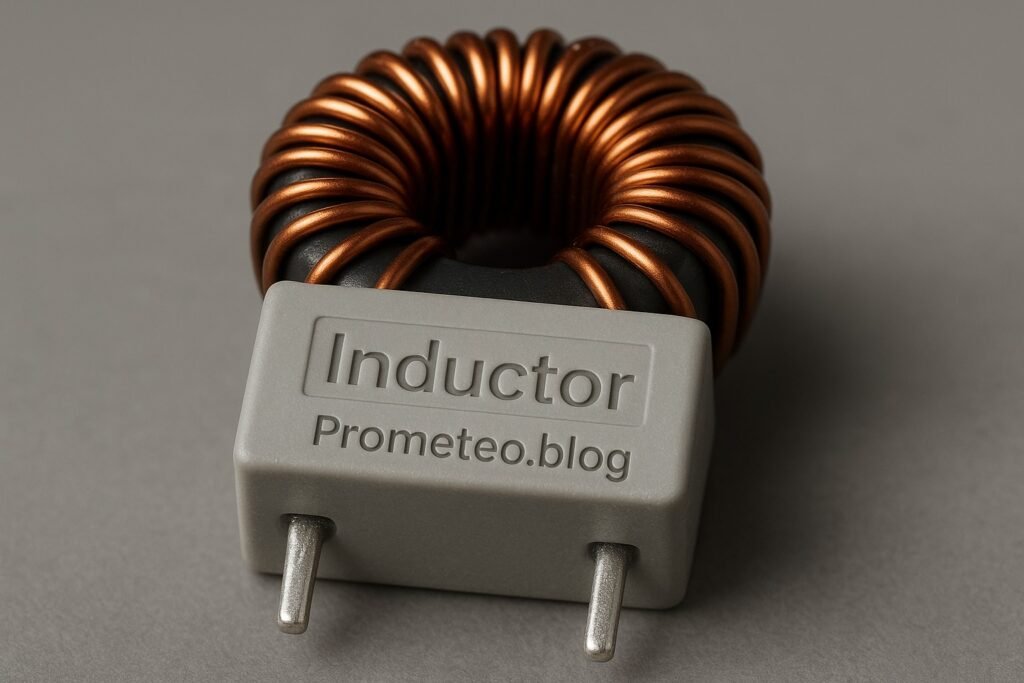
Inductors are passive electrical components that store energy in a magnetic field when electrical current passes through them. They are widely used in various applications, including filters, transformers, energy storage devices, and oscillators. Understanding how inductors work is crucial for any electronics enthusiast or engineer.

Basic Principle

The basic principle of an inductor is Faraday’s Law of Electromagnetic Induction, which states that a changing magnetic field within a closed loop induces an electromotive force (EMF) in that loop. When current flows through an inductor, it creates a magnetic field around it. If the current changes, the magnetic field also changes, inducing a voltage that opposes the change in current. This phenomenon is known as self-inductance and is a fundamental concept in electromagnetism.

To illustrate this with an example, consider a simple circuit with a battery and an inductor. When the circuit is first closed, the inductor resists the sudden increase in current due to its magnetic field. This resistance to change results in a gradual increase in current over time, rather than an instantaneous jump. The time it takes for the current to reach its maximum value is determined by the inductance of the inductor and the resistance in the circuit.

Inductance

Inductance is the property of an inductor that quantifies its ability to store energy in the magnetic field. It is measured in henries (H). The inductance value depends on several factors, such as the number of turns in the coil, the core material, and the physical dimensions of the coil. Higher inductance means a greater ability to store energy. For instance, a coil with more turns will have a higher inductance than a coil with fewer turns, all else being equal.

Inductance can also be influenced by the core material used in the inductor. Ferromagnetic materials, such as iron, can significantly increase the inductance compared to air-core inductors. This is due to the higher magnetic permeability of these materials, which enhances the magnetic field created by the current flowing through the coil.

Applications of Inductors

  1. Energy Storage: Inductors are commonly used in power supplies and converters to temporarily store energy and smooth out voltage levels. They help manage fluctuations in current, ensuring stable operation. For example, in a switching power supply, inductors can store energy during the «on» phase and release it during the «off» phase, maintaining a steady output voltage.

  2. Filters: Inductors are employed in LC (inductor-capacitor) filters to allow certain frequencies to pass while blocking others. They are essential in radio frequency (RF) applications, audio systems, and communication devices. For instance, in a low-pass filter, the inductor blocks high-frequency signals while allowing lower frequencies to pass, which is crucial in audio processing to eliminate unwanted noise.

  3. Transformers: In transformers, inductors are used to transfer energy between circuits through electromagnetic induction. They enable voltage transformation, allowing efficient energy distribution. A transformer consists of two inductors (primary and secondary) wound around a common core. When alternating current flows through the primary inductor, it creates a changing magnetic field that induces a voltage in the secondary inductor.

  4. Oscillators: Inductors play a vital role in oscillator circuits by providing the necessary reactance to produce oscillations at specific frequencies. In a tank circuit, which consists of an inductor and a capacitor, the energy oscillates between the magnetic field of the inductor and the electric field of the capacitor, resulting in a sustained oscillation at a resonant frequency.

  5. Chokes: Inductors are used as chokes to limit the amount of AC current flowing in a circuit, filtering out unwanted signals while allowing DC signals to pass. This is particularly useful in power supply circuits, where it is essential to suppress high-frequency noise that can interfere with the operation of sensitive components.

Behavior in Circuits

When an inductor is connected to a DC power supply, it initially resists the change in current, which leads to a gradual increase in current over time. This behavior is characterized by the time constant, which is determined by the inductance and the resistance in the circuit. The time constant (τ) can be calculated using the formula:

τ = L / R

where L is the inductance in henries and R is the resistance in ohms. Eventually, the current stabilizes, and the inductor behaves like a short circuit, allowing the maximum current to flow.

In an AC circuit, the behavior of inductors is different. They introduce reactance, which is frequency-dependent. The inductive reactance ( X(L) ) can be calculated using the formula:

X(L) = 2πfL

where f is the frequency in hertz and L is the inductance in henries. As the frequency of the AC signal increases, the inductive reactance also increases, leading to less current flow. This property is exploited in filter circuits to allow certain frequencies to pass while blocking others.

For example, in a high-pass filter, an inductor is used to block low-frequency signals while allowing high-frequency signals to pass. Conversely, in a low-pass filter, an inductor is used to allow low-frequency signals to pass while blocking high-frequency signals.

Conclusion

In summary, inductors are essential components in the world of electronics. They offer a unique ability to store energy in a magnetic field and are used in various applications, from power supplies to communication systems. Understanding their function and behavior is fundamental for anyone working with electrical circuits. By grasping the principles of inductance and the applications of inductors, you can enhance your skills and knowledge in electronics significantly.

Key parameters

Parameter Typical Range Unit Note
Inductance 10 1 – 10000 H Common in power applications
DC Resistance 0.5 0.01 – 50 Ω Affects efficiency
Saturation Current 1.5 0.1 – 15 A Maximum current before saturation
Quality Factor (Q) 30 5 – 200 Indicates efficiency
Self-Resonant Frequency 100 kHz 1 kHz – 10 MHz Hz Frequency at which it resonates

The table above summarizes the key parameters associated with inductors. Each parameter plays a vital role in determining the performance and suitability of an inductor for a specific application. For instance, the quality factor (Q) indicates how efficiently an inductor can store and release energy, with higher values representing better performance. Understanding these parameters is crucial when selecting inductors for your projects.

Hands-on practical project: Building a Simple LC Filter

Goal: Create a low-pass LC filter to attenuate high frequencies in an audio signal, verifying that the output signal is lower than -3 dB at 1 kHz.

Estimated time: 45 minutes

Materials

  • 1 × Inductor — 10 mH for the filter circuit.
  • 1 × Capacitor — 100 µF for coupling the signals.
  • 1 × Audio source — Any device with an audio output.
  • 1 × Audio amplifier — For output sound amplification.
  • 2 × 3.5 mm audio cables — To connect audio source and amplifier.
  • 1 × Breadboard — For assembling the circuit.
  • 2 × Jumper wires (red and black) — To make connections.
  • 1 × Multimeter — To measure output levels.

Step-by-step build

  1. Set Up the Breadboard: Start by placing the inductor and capacitor on the breadboard. Ensure they are easily accessible for connections. The inductor should be connected in series with the audio source while the capacitor will be connected to ground.
  2. Check: Ensure components are firmly seated on the breadboard. A loose connection can lead to inconsistent performance.

  3. Connect the Inductor: Connect one terminal of the inductor to the audio source’s output. Connect the other terminal of the inductor to one terminal of the capacitor. This configuration allows the inductor to pass low frequencies while blocking higher ones.

  4. Check: Verify that connections are secure, as any loose wires can disrupt the signal flow.

  5. Connect the Capacitor: Connect the second terminal of the capacitor to the ground rail of the breadboard. This completes the LC filter circuit, allowing it to operate effectively.

  6. Check: Ensure the capacitor is oriented correctly; polarity matters unless it’s a non-polarized type. An incorrectly oriented capacitor can fail and potentially damage the circuit.

  7. Connect the Output: Use jumper wires to connect the output of the LC filter to the audio amplifier’s input. This will allow you to hear the filtered audio signal. Make sure to check the right input channel on the amplifier.

  8. Check: Confirm that connections are made to the correct terminals to ensure proper signal routing.

  9. Power Up the Circuit: Once everything is connected, power up the audio source and the amplifier to begin the testing phase. Adjust the volume on the audio source to ensure a clear signal is being sent.

  10. Check: Listen for audio output; there should be no distortion. If distortion occurs, check the connections and component ratings.

  11. Measure Output Levels: Use the multimeter to measure the output voltage of the audio signal at the amplifier. Adjust the frequency of the audio source to verify the -3 dB point at 1 kHz. Note the changes in output signal as the frequency varies.

  12. Check: Make sure the multimeter is set to the correct mode for AC voltage. Accurate measurements are crucial for validating the filter’s performance.

Testing and validation

  1. Frequency Sweep: Connect a function generator to the input of the LC filter and sweep through frequencies from 100 Hz to 10 kHz. Monitor the output level on the multimeter and note when the output drops below -3 dB.
  2. Check: Document the specific frequencies where the output drops significantly, as this will help you understand the filter’s cutoff characteristics.

  3. Listen to the Filtered Audio: Play music through the audio source and listen to the output from the amplifier. The high frequencies should be attenuated, resulting in a more bass-heavy sound.

  4. Check: Verify that the sound quality matches your expectations. If the high frequencies are still present, recheck your connections and component values.

Extend the project

  • Experiment with different inductor and capacitor values to change cutoff frequencies. This will provide insight into how component values affect filter performance.
  • Implement a potentiometer to adjust the resistance and fine-tune the filter. This addition allows for more dynamic control over the cutoff frequency.
  • Add a second filter stage for sharper frequency attenuation. By cascading filters, you can create more complex filtering effects.

Safety

  • Always ensure that the circuit is powered off when making adjustments. This precaution helps prevent accidental shocks or component damage.
  • Avoid touching live wires during operation to prevent shocks. Use insulated tools when necessary.
  • Keep components within their specified ratings to prevent overheating. Exceeding ratings can lead to component failure and potentially dangerous situations.

Common mistakes and how to avoid them

  • Incorrect Polarity: Ensure capacitors are connected with the correct polarity to avoid circuit failure. Always check the markings on the capacitor to identify the positive and negative leads.
  • Loose Connections: Double-check all wire connections to prevent intermittent signals. A loose connection can lead to unpredictable circuit behavior.
  • Overloading Components: Verify that components are rated for the expected voltage and current levels. Using components beyond their ratings can cause overheating and failure.
  • Ignoring Inductor Ratings: Make sure the inductor’s saturation current is not exceeded during operation. Exceeding this limit can lead to a loss of inductance and circuit malfunction.
  • Neglecting Ground Connections: Always provide a proper ground connection to avoid circuit malfunction. A floating ground can cause erratic behavior and signal integrity issues.

Conclusion

Inductors are pivotal in many electronic applications, from filtering signals to energy storage. By understanding how they work and implementing practical projects, you can enhance your knowledge and skills in electronics. I encourage you to explore different configurations and applications. Embrace the learning process and experiment with inductors in your circuits. The journey of discovery in electronics is continuous, and each project brings you closer to mastery. More information at prometeo.blog

Third-party readings

Find this product and/or books on this topic on Amazon

Go to Amazon

As an Amazon Associate, I earn from qualifying purchases. If you buy through this link, you help keep this project running.

Quick Quiz

Question 1: What do inductors primarily store?


Question 2: Which law explains the operation of inductors?


Question 3: What happens to the magnetic field when the current through an inductor changes?


Question 4: In which of the following applications are inductors commonly used?


Question 5: What is the phenomenon called when an inductor induces a voltage that opposes a change in current?


Micro Tutorial: Inductor

Carlos Núñez Zorrilla
Electronics & Computer Engineer

Telecommunications Electronics Engineer and Computer Engineer (official degrees in Spain).

Follow me:


Micro Tutorial: Capacitor

Micro Tutorial: Capacitor — imagen destacada

Introduction

Have you ever encountered a sudden flicker of lights when you plug in an appliance? That’s a capacitor at work, smoothing out voltage fluctuations. Understanding capacitors can help you appreciate the role they play in everyday electronics. Capacitors are ubiquitous in all electronic devices, from simple circuits to complex machinery, and their importance cannot be overstated. By the end of this tutorial, you will gain a comprehensive understanding of capacitors, including their operation, applications, and how to effectively utilize them in your own projects.

Capacitors are passive electronic components that store electrical energy in an electric field. They are essential for maintaining stable voltage levels, filtering signals, and timing applications. By learning how capacitors function and where they are used, you’ll be better equipped to design and troubleshoot electronic circuits. Whether you’re a hobbyist, student, or professional engineer, this knowledge will enhance your understanding of electronics and empower you to create more effective and reliable circuits.

What it’s used for and how it works

Capacitors are fundamental components in the world of electronics, widely used for various applications. They store and release electrical energy, acting as temporary batteries to stabilize voltage and power supply in circuits. Let’s dive deeper into how they work and where they are typically used.

How Capacitors Store Energy

Capacitors consist of two conductive plates separated by an insulating material called a dielectric. When a voltage is applied across the plates, an electric field forms, allowing the capacitor to store energy. The stored energy can be released when needed, making capacitors essential in smoothing out voltage fluctuations in circuits.

The energy (E) stored in a capacitor can be calculated using the formula:

E = 1 / 2 C V^2

Where:
– E is the energy in joules (J),
– C is the capacitance in farads (F),
– V is the voltage in volts (V).

This equation illustrates that the energy stored in a capacitor increases with both the capacitance and the square of the voltage applied. Therefore, a capacitor with a higher capacitance or a higher voltage will store significantly more energy.

Uses of Capacitors

Capacitors have a broad range of applications, including:

  1. Power Supply Smoothing: Capacitors are often used in power supply circuits to smooth out the output voltage. After rectification, the capacitor charges and discharges, minimizing voltage ripple. This is especially critical in power supplies for computers and audio equipment, where stable voltage is necessary for optimal performance.

  2. Signal Coupling and Decoupling: In audio and RF circuits, capacitors allow AC signals to pass while blocking DC components. They help maintain signal integrity by decoupling different sections of a circuit. For instance, in audio amplifiers, capacitors can couple audio signals while preventing DC bias from affecting the output.

  3. Timing Applications: Capacitors can be used in timing circuits alongside resistors to create delays or oscillations. This is useful in applications like blinking LED circuits, where the timing of the LED’s on-and-off cycle is controlled by the charging and discharging of the capacitor.

  4. Energy Storage: In applications like flash photography, capacitors temporarily store energy and release it quickly when needed, providing a burst of power. This allows photographers to capture high-speed action shots with a quick flash.

  5. Filtering: Capacitors are used in filters to separate different frequency components of signals. This is crucial in audio processing and communication systems, where unwanted frequencies must be removed to ensure clear sound transmission.

The Physics Behind Capacitors

The amount of charge a capacitor can store is determined by its capacitance, measured in farads (F). The relationship between charge (Q), voltage (V), and capacitance (C) is given by the formula:

Q = C × V

This equation shows that the charge stored in a capacitor increases with both the voltage applied and the capacitance of the capacitor. Therefore, a larger capacitor (higher capacitance) can store more charge at the same voltage, making it more effective for energy storage applications.

Types of Capacitors

There are several types of capacitors, each with specific characteristics:

  • Ceramic Capacitors: Commonly used in high-frequency applications due to their low equivalent series resistance (ESR). They are non-polarized and can handle high voltages, making them ideal for decoupling and filtering applications.

  • Electrolytic Capacitors: Polarized capacitors that provide high capacitance values, suitable for power supply filtering. They are often used in applications where large capacitance is required, such as in power supplies and audio amplifiers.

  • Film Capacitors: Known for stability and low loss, making them ideal for timing applications. They have a longer lifespan and are less prone to failure compared to electrolytic capacitors.

  • Tantalum Capacitors: Similar to electrolytic but offer higher capacitance in a smaller package, often used in compact devices. They are stable and reliable but can be more expensive.

  • Supercapacitors: These can store much more energy than traditional capacitors and are used in applications requiring rapid charging and discharging. Supercapacitors are often found in energy storage systems and hybrid vehicles.

Factors Affecting Performance

The performance of a capacitor is influenced by various factors, including:

  • Capacitance Value: The higher the capacitance, the more charge the capacitor can store. Selecting the right capacitance value is crucial for ensuring the capacitor meets the requirements of your circuit.

  • Voltage Rating: Always ensure that the voltage applied does not exceed the rated voltage to prevent failure. Exceeding the voltage rating can lead to breakdown of the dielectric material and catastrophic failure of the capacitor.

  • Temperature Coefficient: Capacitors can change their capacitance value with temperature variations, which is critical in precision applications. Understanding the temperature coefficient of a capacitor is important for applications that require stable performance over a range of temperatures.

Applications in Everyday Life

Capacitors are found in almost all electronic devices, from smartphones to microwaves. They help manage power supply stability, enhance audio quality, and even play a role in energy-efficient designs. For example, in a smartphone, capacitors are used to smooth the power supply to the processor, ensuring that it operates reliably without voltage fluctuations. In audio systems, capacitors filter out unwanted noise, allowing for clear sound reproduction. Understanding capacitors equips you with the knowledge to troubleshoot and innovate in electronic projects, making them an essential component of modern technology.

Key parameters

Parameter Typical Range Unit Note
Capacitance 10 µF 1 pF – 10 F F Main specification
Voltage Rating 25 V 6.3 V – 1000 V V Maximum voltage limit
Equivalent Series Resistance (ESR) 0.1 Ω 0.01 Ω – 100 Ω Ω Affects performance at high frequencies
Temperature Coefficient ±10% ±1% – ±20% Variation with temperature
Leakage Current 1 µA 0.01 µA – 10 mA A Current loss over time

Understanding these key parameters will help you select the right capacitor for your specific needs. For example, if you are designing a power supply circuit, you may prioritize a capacitor with a high capacitance and a suitable voltage rating to ensure stability and reliability. Conversely, in high-frequency applications, you may focus on minimizing ESR to enhance performance.

Hands-on practical project: Capacitor-based LED Blinking Circuit

Goal: Control an LED to blink at a steady rate using a capacitor, verifying that the LED blinks at a frequency of 1 Hz.

Estimated time: 45 minutes.

Materials

  • 1 × 220 Ω resistor — Current limiting for LED.
  • 1 × 10 µF capacitor — Stores charge to control blinking.
  • 1 × LED — Visual output for the circuit.
  • 1 × NPN transistor — Acts as a switch for the LED.
  • 1 × 9 V battery — Power source for the circuit.
  • 1 × breadboard — For easy circuit assembly.
  • 2 × jumper wires (red and black) — For making connections.
  • 1 × 1 kΩ resistor — Base resistor for the transistor.

Step-by-step build

  1. Place the components on the breadboard
    Start by placing the NPN transistor on the breadboard. Connect the collector pin of the transistor to the anode of the LED. The LED’s cathode should connect to the ground rail of the breadboard. This setup allows the transistor to control the LED.
  2. Check: Ensure the LED’s anode is correctly connected to the collector.

  3. Connect the resistor and capacitor
    Connect the 220 Ω resistor from the LED’s anode to the positive rail. Next, attach the capacitor across the collector and emitter of the transistor, ensuring the positive side connects to the collector. This configuration allows the capacitor to charge and discharge, controlling the blinking rate.

  4. Check: Confirm the capacitor’s positive lead is in the correct orientation.

  5. Add the base resistor
    Connect the base of the transistor to one end of the 1 kΩ resistor, and connect the other end to the positive rail. This resistor limits the current flowing into the base of the transistor, protecting it from damage. The base controls the transistor’s switching behavior.

  6. Check: Double-check that the base resistor is correctly connected.

  7. Connect the power supply
    Finally, connect the 9 V battery’s positive terminal to the positive rail of the breadboard and the negative terminal to the ground rail. Ensure all connections are secure. This power will energize the circuit, allowing the capacitor to function correctly.

  8. Check: Verify that the battery connections are secure and correct.

Testing and validation

  1. Power up the circuit
    Once everything is connected, switch on the power by connecting the battery. Observe the LED. It should start blinking at a steady rate. If it does not blink, recheck all connections, especially the capacitor and transistor orientation.
  2. Check: Confirm the LED blinks at approximately 1 Hz.

  3. Adjust the blinking rate
    To modify the blinking speed, you can experiment with different capacitance values or resistor values. Replacing the 10 µF capacitor with a higher value will slow the blink rate, while a lower value will speed it up. Test and adjust accordingly.

  4. Check: Ensure the LED still blinks steadily after adjustments.

Extend the project

  • Use a variable resistor to control the blink rate.
  • Add more LEDs in parallel to create a blinking pattern.
  • Implement a different type of capacitor to see how it affects performance.
  • Integrate a microcontroller to add more complex blinking patterns.

Safety

  • Always double-check the voltage rating of the components before use.
  • Ensure that the power supply is disconnected while assembling the circuit.
  • Avoid touching live wires when the circuit is powered.
  • Use resistors with appropriate ratings to prevent overheating.
  • Work in a dry environment to prevent any short circuits.

Common mistakes and how to avoid them

  • Incorrect Capacitor Polarity: Ensure that polarized capacitors (like electrolytics) are installed in the correct orientation. Check the markings before soldering. If a polarized capacitor is connected backward, it can fail spectacularly, sometimes exploding.

  • Overloading the Capacitor: Do not exceed the voltage rating; otherwise, the capacitor may fail. Always check the specifications. If unsure, opt for a capacitor with a higher voltage rating than required.

  • Loose Connections: In breadboard setups, ensure all connections are secure. Loose connections can lead to intermittent issues. A good practice is to gently tug on wires to confirm they are firmly seated.

  • Wrong Component Values: Double-check resistor and capacitor values before assembly. Using incorrect values may lead to unexpected results. It’s advisable to use a multimeter to verify component values if in doubt.

  • Ignoring Temperature Effects: Be mindful that capacitance can change with temperature. For critical applications, consider using temperature-compensated capacitors. Always consult the datasheet for the capacitor to understand its behavior under varying conditions.

Conclusion

Understanding capacitors is crucial for anyone working with electronics. They play pivotal roles in smoothing power supplies, filtering signals, and timing applications. By experimenting with hands-on projects, you can appreciate their functionality even more. So, gather your materials, build something exciting, and dive deeper into the world of capacitors! More information at prometeo.blog

Third-party readings

Find this product and/or books on this topic on Amazon

Go to Amazon

As an Amazon Associate, I earn from qualifying purchases. If you buy through this link, you help keep this project running.

Quick Quiz

Question 1: What is the primary function of a capacitor?


Question 2: What are the two main components of a capacitor?


Question 3: In which application are capacitors commonly used?


Question 4: What happens when a voltage is applied across a capacitor?


Question 5: Who can benefit from understanding capacitors?


Micro Tutorial: Capacitor

Carlos Núñez Zorrilla
Electronics & Computer Engineer

Telecommunications Electronics Engineer and Computer Engineer (official degrees in Spain).

Follow me:


Micro Tutorial: Transistor

Micro Tutorial: Transistor — imagen destacada

Introduction

Transistors are often considered the building blocks of modern electronics. They revolutionized the field by replacing bulky vacuum tubes, allowing devices to become smaller, more efficient, and more reliable. I still remember the first time I built a simple circuit using a transistor; it felt like I was unlocking a new level in my understanding of electronics. The excitement of seeing a tiny component control a larger electrical flow is a thrilling experience that every electronics enthusiast should have. In this tutorial, we will delve deeper into the world of transistors, exploring their functionality, applications, and how you can start using them in your projects.

What it’s used for and how it works

Transistors are semiconductor devices that can act as switches or amplifiers, allowing you to control electrical signals. They form the backbone of numerous electronic devices, including radios, computers, and smartphones. In essence, a transistor can regulate the flow of current or voltage in a circuit, which is crucial for signal processing.

How does a transistor work?

At its core, a transistor consists of three layers of semiconductor material, typically silicon, which are doped with impurities to create regions of positive (p-type) and negative (n-type) charge carriers. The three terminals of a transistor are called the emitter, base, and collector.

  • Emitter: This terminal emits charge carriers (electrons or holes) into the base region.
  • Base: This is the control terminal that regulates the flow of carriers from the emitter to the collector.
  • Collector: This terminal collects the charge carriers from the emitter.

In a simple configuration, when a small current flows into the base terminal, it allows a much larger current to flow from the collector to the emitter. This principle is what allows transistors to function as amplifiers. For instance, if you apply a small voltage to the base, it can control a much larger current flowing through the collector-emitter path. This is fundamental in applications such as audio amplification, where a weak signal needs to be boosted.

Types of transistors

There are several types of transistors, but the most common ones are Bipolar Junction Transistors (BJTs) and Field Effect Transistors (FETs).

  • BJTs: These transistors use both electron and hole charge carriers. They come in two varieties: NPN and PNP.
  • In an NPN transistor, electrons flow from the collector to the emitter when activated, while in a PNP transistor, holes flow in the opposite direction. The operation of BJTs is based on the principle of current control, where a small base current controls a larger collector current.

  • FETs: These transistors, including MOSFETs and JFETs, use an electric field to control the flow of current. FETs are often preferred for high-speed applications due to their high input impedance and low power consumption. Unlike BJTs, FETs are voltage-controlled devices, meaning that a small voltage applied to the gate terminal can control a much larger current flowing from the source to the drain.

Applications of transistors

Transistors have a wide range of applications. In amplifiers, they boost signals for audio and radio frequencies. For example, in audio equipment, a small audio signal from a microphone can be amplified by a transistor circuit to drive speakers. In digital circuits, they function as switches, enabling the binary operations that form the basis of computer logic. Each bit of data in a computer is represented by a transistor being either on or off, which corresponds to the binary states of 1 and 0.

Furthermore, transistors are crucial in power regulation circuits, where they help manage voltage and current levels effectively. They are used in voltage regulators to maintain a constant output voltage despite variations in input voltage or load conditions.

Amplification and switching

In amplification, a small input current can control a larger output current. This is vital in audio applications, where a weak audio signal needs amplification for speakers. For example, in a guitar amplifier, the weak signal from the guitar pickups is amplified by transistors to drive the speaker, producing a louder sound.

On the other hand, in switching applications, transistors can turn circuits on or off based on input signals. This capability is exploited in everything from simple light switches to complex computer processors. For instance, in a microprocessor, millions of transistors switch on and off to perform calculations and process data at incredible speeds.

Importance in modern electronics

Without transistors, modern electronics as we know them would not exist. They have replaced vacuum tubes in most applications due to their smaller size, increased reliability, and lower power consumption. The development of integrated circuits, which combine thousands or millions of transistors on a single chip, has further propelled technological advancements, enabling the creation of compact and powerful devices. As such, understanding how transistors work is fundamental for anyone interested in electronics.

In summary, transistors are essential components that enable the functionality of countless devices we use daily. Their ability to amplify signals and switch currents makes them invaluable in both analog and digital electronics.

Key parameters

Parameter Typical Range Unit Note
Current Gain (hFE) 100 20 – 1000 Ratio of output to input current
Collector Current (IC) 10 mA 1 mA – 1 A mA Maximum collector current
Base Current (IB) 0.1 mA 0.01 mA – 1 mA mA Input current required
Collector-Emitter Voltage (VCE) 40 V 1 V – 60 V V Maximum voltage between collector and emitter
Power Dissipation (PD) 500 mW 100 mW – 2 W mW Maximum power the transistor can handle
Operating Temperature (T) 25°C -55°C to 150°C °C Range of operating temperature

Understanding these parameters is crucial for selecting the right transistor for a specific application. For example, if you are designing a circuit that requires high current amplification, you would look for a transistor with a high current gain (hFE) and an adequate collector current (IC) rating. Similarly, if your application involves high voltage, you’d need to ensure that the collector-emitter voltage (VCE) rating is sufficient to handle the expected voltage levels.

Hands-on practical project: Basic Transistor Switch

Goal: Build a simple switch using a transistor to control an LED.
Estimated time: 30 minutes.

Materials

  • 1 × NPN transistor — Acts as the switch.
  • 1 × 220 Ω resistor — Limits current to the LED.
  • 1 × 10 kΩ resistor — Base resistor for the transistor.
  • 1 × LED — Light-emitting diode for visual output.
  • 1 × 9 V battery — Power source for the circuit.
  • 1 × breadboard — Platform for building the circuit.
  • 2 × jumper wires (red and black) — Connections for power and ground.

Step-by-step build

  1. Place the transistor on the breadboard
    Start by inserting the NPN transistor into the breadboard. Ensure that the flat side of the transistor is facing you. The left pin will be the collector, the middle pin will be the base, and the right pin will be the emitter.
  2. Check: The transistor is oriented correctly.

  3. Connect the base resistor
    Take the 10 kΩ resistor and connect one end to the base pin (middle pin) of the transistor. Connect the other end of the resistor to a jumper wire that will connect to the positive terminal of the battery.

  4. Check: Resistor is connected to the base.

  5. Connect the collector
    Now, connect the collector pin (left pin) to one end of the 220 Ω resistor. Connect the other end of the resistor to the anode (longer lead) of the LED. The cathode (shorter lead) of the LED should be connected to the negative terminal of the battery.

  6. Check: The collector is connected to the resistor and LED.

  7. Connect the emitter
    Connect the emitter pin (right pin) of the transistor directly to the negative terminal of the battery. This establishes a common ground for the circuit, allowing current to flow through the LED when the transistor is activated.

  8. Check: The emitter is correctly grounded.

  9. Final connections
    Connect the positive terminal of the battery to the free end of the base resistor (10 kΩ). This connection allows the base of the transistor to receive power, enabling it to switch on the LED when activated.

  10. Check: All connections are secure and correct.

Testing and validation

  1. Power on the circuit
    Connect the battery to the circuit and observe the LED. If everything is connected correctly, the LED should light up. If it doesn’t, double-check all connections, especially the orientation of the transistor and the polarity of the LED.
  2. Check: LED lights up when power is applied.

  3. Control the LED
    You can control the LED by connecting a small momentary switch or another circuit to the base resistor. When activated, the switch should allow current to flow into the base, turning the LED on.

  4. Check: The LED responds to input control.

Extend the project

  • Add multiple LEDs: Create a simple light chaser by connecting multiple LEDs in parallel and controlling them with the same transistor.
  • Use different transistor types: Experiment with BJTs and FETs to compare their performance in switching applications.
  • Integrate a potentiometer: Control the brightness of the LED by using a potentiometer in place of the base resistor.
  • Create a more complex circuit: Use multiple transistors to build a simple flip-flop circuit, which can toggle the state of the LED based on input.

Safety

  • Always check the connections before powering the circuit.
  • Ensure the transistor is not overheated during operation. If it feels hot, disconnect the power immediately.
  • Use resistors to limit the current to the LEDs and prevent them from burning out.
  • Be cautious with battery connections to avoid short circuits; ensure that positive and negative terminals are connected correctly.
  • Disconnect the power when making adjustments to avoid accidental shocks or damage to components.

Common mistakes and how to avoid them

  • Incorrect transistor orientation: Always double-check the pin layout of the transistor. A simple mistake here can prevent the circuit from functioning.
  • Wrong resistor values: Using resistors with incorrect values can lead to excessive current flowing through the LED or transistor, potentially damaging them. Always verify resistor values with a multimeter if unsure.
  • Not securing connections: Loose connections can lead to intermittent faults. Make sure all jumper wires are firmly inserted into the breadboard.
  • Ignoring safety precautions: Always follow safety guidelines when working with electrical components. This includes wearing safety goggles and working in a dry area.
  • Overloading the transistor: Stay within the specified current and voltage ratings for the transistor you are using. Exceeding these ratings can cause the transistor to fail.

Conclusion

In summary, transistors are fundamental components in electronics, serving as switches and amplifiers. Understanding their operation and applications is essential for any aspiring engineer or hobbyist. By practicing with simple projects, you can grasp their importance and functionality better. The hands-on experience of building circuits not only solidifies your knowledge but also inspires creativity in your designs. So, why not start experimenting with transistors today? You’ll be amazed at what you can create! More information at prometeo.blog

Third-party readings

Find this product and/or books on this topic on Amazon

Go to Amazon

As an Amazon Associate, I earn from qualifying purchases. If you buy through this link, you help keep this project running.

Quick Quiz

Question 1: What are transistors often considered to be in modern electronics?


Question 2: What is the main function of a transistor?


Question 3: Which material is commonly used to make transistors?


Question 4: What are the three terminals of a transistor called?


Question 5: What role does the base terminal play in a transistor?


Micro Tutorial: Transistor

Carlos Núñez Zorrilla
Electronics & Computer Engineer

Telecommunications Electronics Engineer and Computer Engineer (official degrees in Spain).

Follow me:


Micro Tutorial: Resistor

Micro Tutorial: Resistor — imagen destacada

Introduction

In my early days as an electronics enthusiast, I vividly remember the first time I connected a resistor incorrectly. The circuit failed to work, and I was puzzled, staring at the components as if they held the secrets to the universe. It was then I learned how crucial resistors are in controlling current and ensuring the proper functioning of electronic circuits. Resistors are not just passive components; they are the unsung heroes of circuit design, quietly shaping the behavior of our electronic devices. In this tutorial, we will explore the essential role of resistors, how they operate, their key parameters, and even build a hands-on project to solidify our understanding.

What it’s used for and how it works

Resistors are fundamental components in electronics, serving various purposes across countless applications. Their primary role is to control the flow of electric current by introducing resistance into a circuit. The most common function of a resistor is to limit the current flowing through a circuit, thereby protecting sensitive components like LEDs, transistors, and integrated circuits from excessive current that could lead to damage.

When you connect a resistor in series with a load, such as an LED, it divides the voltage across the load and the resistor according to Ohm’s Law. Ohm’s Law states that the voltage (V) across a resistor is equal to the current (I) flowing through it multiplied by its resistance (R). This relationship can be expressed by the formula:

V = I × R

This formula allows you to calculate the necessary resistance needed to achieve a specific voltage drop or current level in your circuit. For instance, if you want to limit the current through an LED to a safe value, you can calculate the required resistance based on the LED’s forward voltage and desired current.

Example of Using Ohm’s Law

Let’s say you have an LED with a forward voltage of 2V and you want to limit the current to 20mA (0.02A). According to Ohm’s Law, the voltage drop across the resistor (V(R)) can be calculated as follows:

  1. Subtract the LED forward voltage from the supply voltage (let’s assume a 9V battery):
    V(R) = V(supply) – V(LED) = 9V – 2V = 7V

  2. Now, using Ohm’s Law, we can find the resistance:
    R = V(R) / I = 7V / 0.02A = 350Ω

In this case, you would need a resistor of approximately 350Ω to ensure the LED operates safely. Since 350Ω is not a standard resistor value, you could use a 360Ω resistor instead, which is a common value.

Applications of Resistors

Resistors have a multitude of applications in electronic circuits:
Voltage Dividers: Resistors can be arranged in series to create a voltage divider, allowing you to obtain a specific voltage from a higher voltage source.
Pull-up and Pull-down Resistors: In digital logic circuits, resistors are used to ensure a defined logic level when no active devices are driving the line.
Filters: In combination with capacitors, resistors can form filters that allow certain frequencies to pass while attenuating others, essential in audio and signal processing applications.
Biasing Transistors: Resistors are used to set the operating point of transistors in amplifiers, ensuring they function within their optimal range.
Timing Circuits: In conjunction with capacitors, resistors can create timing circuits that control the duration of events in electronic systems.

Types of Resistors

Resistors can be classified into two main types:
1. Fixed Resistors: These have a constant resistance value and are the most commonly used type in circuits.
2. Variable Resistors (Potentiometers): These allow you to adjust the resistance value manually, making them useful for applications such as volume controls or brightness adjustments in lighting systems.

Power Dissipation

In addition to controlling current, resistors also dissipate energy in the form of heat. This heat generation is an essential aspect to consider, as overheating can damage both the resistor and surrounding components. Therefore, resistors are rated for power, commonly expressed in watts (W), indicating the maximum power they can safely dissipate. Selecting the appropriate resistor rating is crucial to ensure reliability and safety in your circuits.

In summary, resistors are vital components in electronic circuits, providing control over current flow, enabling voltage division, and protecting sensitive components. Their diverse applications and essential functions make them a cornerstone of electronic design. Understanding their function and characteristics is crucial for anyone venturing into the world of electronics.

Key parameters

Parameter Typical Range Unit Note
Resistance 220 1 – 10 M Ω Value determines current flow.
Power Rating 0.25 0.0625 – 5 W Maximum power dissipation.
Tolerance 5 1 – 20 % Accuracy of resistor value.
Temperature Coefficient 100 50 – 2000 ppm/°C Change in resistance with temp.
Voltage Rating 250 50 – 500 V Maximum voltage across resistor.
Size 0.25 0.1 – 1.5 in Physical dimensions of resistor.
Material Carbon Film Metal Film, Wirewound Type of construction.

Explanation of Key Parameters

  • Resistance: Measured in ohms (Ω), this determines how much the resistor opposes the flow of current. A higher resistance value results in lower current flow for a given voltage.
  • Power Rating: This indicates the maximum amount of power (in watts) that the resistor can safely dissipate without overheating. Exceeding this rating can lead to resistor failure.
  • Tolerance: This percentage indicates how much the actual resistance can vary from its stated value. A lower tolerance means a more precise resistor.
  • Temperature Coefficient: This value indicates how much the resistance changes with temperature, expressed in parts per million per degree Celsius (ppm/°C). A lower temperature coefficient is preferable for precision applications.
  • Voltage Rating: This is the maximum voltage that can be applied across the resistor without risking breakdown or failure.
  • Size: The physical dimensions of the resistor can affect its power rating and suitability for specific applications.
  • Material: Different materials affect the performance and characteristics of the resistor, influencing factors like temperature stability and noise.

Hands-on practical project: LED Resistor Circuit

Goal: Build a simple LED circuit with a resistor to control brightness.
Estimated time: 30 minutes.

Materials

  • 1 × 220 Ω resistor — To limit the LED current.
  • 1 × LED — Light source for the circuit.
  • 1 × 9 V battery — Power source for the circuit.
  • 1 × battery holder — To hold the 9 V battery.
  • 2 × jumper wires (red and black) — For connections.
  • 1 × breadboard — To build the circuit easily.
  • 1 × switch — To turn the LED on and off.

Step-by-step build

  1. Prepare the breadboard
    Start by placing the breadboard on your workspace. Ensure it is free from any debris or conductive materials. Next, identify the power rails, which are typically marked with red and blue lines. These will supply power to your circuit.
  2. Check: Ensure the breadboard is clean and ready for use.

  3. Connect the battery holder
    Insert the battery holder into the breadboard, ensuring the positive side connects to the power rail (red) and the negative side connects to the ground rail (blue). This setup will allow you to power the circuit effectively.

  4. Check: Confirm the correct orientation of the battery holder to avoid reverse polarity.

  5. Insert the LED
    Place the LED on the breadboard with the longer leg (anode) connected to the positive rail and the shorter leg (cathode) connected to an empty row on the breadboard. Make sure that the LED is oriented correctly; otherwise, it won’t light up.

  6. Check: Verify the LED orientation before proceeding to ensure proper functionality.

  7. Add the resistor
    Connect one end of the 220 Ω resistor to the cathode of the LED, and the other end to the ground rail. The resistor will limit the current flowing through the LED, preventing it from burning out. Make sure the resistor is firmly placed in the breadboard.

  8. Check: Ensure the resistor is connected properly to avoid circuit failure.

  9. Wire the switch
    Insert the switch into the breadboard. Connect one terminal of the switch to the positive rail and the other terminal to the anode of the LED. This setup will allow you to control the flow of electricity to the LED.

  10. Check: Confirm the switch is properly connected to ensure it functions correctly.

  11. Insert the battery
    Finally, insert the 9 V battery into the battery holder. Ensure that the battery is oriented correctly, with the positive side facing the positive terminal of the holder. This completes your circuit, and the LED should light up when the switch is closed.

  12. Check: Double-check the connections are secure before powering the circuit.

Testing and validation

  1. Test the circuit
    Flip the switch to the ‘ON’ position. The LED should illuminate brightly. If it does not light up, recheck all connections and the orientation of the LED. Ensure the resistor is connected correctly as well.
  2. Check: Verify the LED is lit and functioning as expected.

  3. Measure voltage across the LED
    Using a multimeter, measure the voltage across the LED. This will help you confirm that the circuit is functioning correctly and that the voltage drop is within the LED’s specifications.

  4. Check: Ensure the voltage reading is appropriate and within the LED’s rated voltage.

Extend the project

  • Experiment with Different Resistor Values: Use different resistors to see the effect on LED brightness. This will help you understand how resistance affects current flow and LED intensity.
  • Add Multiple LEDs: Connect multiple LEDs in series or parallel to create more complex circuits. This will teach you about the implications of current and voltage in different configurations.
  • Use a Potentiometer: Instead of a fixed resistor, try using a potentiometer for adjustable brightness. This will give you hands-on experience with variable resistors.
  • Implement a Second Switch: Create a multi-mode LED circuit by adding a second switch to control different LED patterns or brightness levels.

Safety

  • Always Disconnect Power: Before making changes to the circuit, ensure that the power is turned off to avoid electric shock or component damage.
  • Handle Components Gently: LEDs and other components can be fragile; handle them with care to avoid damage.
  • Check Resistor Ratings: Ensure the resistor’s power rating is adequate for your circuit configuration to prevent overheating.
  • Avoid Short Circuits: Keep wires separated and secured to prevent accidental short circuits that could damage components.
  • Be Cautious with Battery Connections: Ensure proper connections to prevent sparks or overheating.

Common mistakes and how to avoid them

  • Incorrect LED Orientation: Always check the anode and cathode before powering the circuit. A simple mistake can prevent the LED from lighting up.
  • Using the Wrong Resistor Value: Calculate the needed resistance carefully to avoid excessive current through the LED, which can lead to failure.
  • Not Securing Connections: Ensure all wires and components are firmly connected to avoid intermittent connections that can cause circuit malfunction.
  • Overloading the Resistor: Choose a resistor with an appropriate power rating to prevent overheating and damage.
  • Skipping Safety Checks: Always follow safety protocols when working with circuits to prevent accidents and ensure a safe working environment.

Conclusion

Understanding resistors is crucial for anyone interested in electronics. They play a vital role in controlling current, protecting components, and ensuring circuit functionality. Whether you’re building simple projects or complex devices, knowing how to use resistors effectively will enhance your skills. Start experimenting with different resistor values and configurations to see their effects in action. Happy building! More information at prometeo.blog

Third-party readings

Find this product and/or books on this topic on Amazon

Go to Amazon

As an Amazon Associate, I earn from qualifying purchases. If you buy through this link, you help keep this project running.

Quick Quiz

Question 1: What is the primary role of a resistor in an electronic circuit?


Question 2: According to Ohm’s Law, what is the formula to calculate the voltage across a resistor?


Question 3: What could happen if a resistor is connected incorrectly in a circuit?


Question 4: What does introducing resistance into a circuit primarily protect?


Question 5: When a resistor is connected in series with an LED, what does it do to the voltage?


Micro Tutorial: Resistor

Carlos Núñez Zorrilla
Electronics & Computer Engineer

Telecommunications Electronics Engineer and Computer Engineer (official degrees in Spain).

Follow me:


Micro Tutorial: SSD Hard Drive

Micro Tutorial: Disco Duro SSD — imagen destacada

Introduction

Have you ever wondered why your friend’s laptop boots up in seconds while yours takes an eternity? This often boils down to the type of storage used. In this tutorial, we will dive into the world of Solid State Drives (SSD), exploring their workings, applications, and what makes them tick. As technology continues to evolve, understanding SSDs becomes increasingly important for anyone looking to optimize their computing experience.

What it’s used for and how it works

Solid State Drives, or SSDs, are primarily used for storing data in computers and other devices. Unlike traditional hard drives (HDDs) that use spinning disks to read/write data, SSDs employ flash memory technology, which allows for much faster data access and transfer speeds. Now, let’s break down how SSDs work.

How SSDs Work

At the heart of an SSD is NAND flash memory, which consists of memory cells that store bits of data. These memory cells are organized into pages, and pages are grouped into blocks. When you write data, it is stored in these memory cells. The absence of moving parts in SSDs is a key factor in their speed and reliability. Unlike HDDs, where the read/write head moves across the platters, SSDs can access data almost instantaneously.

Moreover, SSDs operate using a controller that manages data storage and retrieval. This controller is responsible for tasks such as wear leveling, garbage collection, and error correction.

  • Wear Leveling: This process ensures that all memory cells are used evenly, which helps to prolong the lifespan of the SSD. By distributing write and erase cycles across the memory cells, wear leveling prevents any single cell from wearing out prematurely.

  • Garbage Collection: Over time, SSDs accumulate data that is no longer in use. Garbage collection helps to manage this unused data by consolidating it, freeing up space and improving performance. This process can occur in the background without user intervention, ensuring the SSD remains efficient.

  • Error Correction: SSDs are equipped with error correction codes (ECC) that help detect and correct data corruption. This feature ensures data integrity and reliability, making SSDs a safe choice for critical data storage.

Types of SSDs

There are several types of SSDs available, each designed for various applications. The most common ones include:

  1. SATA SSDs: These use the SATA interface, similar to traditional HDDs, making them compatible with most computers. However, they are not as fast as other types. SATA SSDs are a great choice for those looking to upgrade from an HDD without needing the highest performance.

  2. NVMe SSDs: Utilizing the PCIe interface, NVMe drives offer significantly faster data transfer rates than SATA SSDs. They are ideal for high-performance applications, such as gaming, video editing, and data-intensive tasks. NVMe SSDs can achieve read speeds exceeding 3000 MB/s, making them a preferred choice for power users.

  3. M.2 and U.2 SSDs: These are form factors that provide a compact design. M.2 drives are often seen in laptops and desktops due to their small size, while U.2 drives are used in enterprise solutions. M.2 SSDs can be either SATA or NVMe, so it’s essential to check the specifications before purchasing.

Applications of SSDs

SSDs are widely used in various applications, including:

  • Personal Computers: Most modern laptops and desktops come equipped with SSDs to enhance performance. Users experience faster boot times and application loading, making everyday tasks smoother.

  • Gaming Consoles: Gamers benefit from SSDs due to their quick load times, which significantly improve gaming experiences. With an SSD, games load faster, and players can jump into action without lengthy waiting periods.

  • Data Centers: Businesses use SSDs in servers for faster data access and improved efficiency. In environments where speed and reliability are critical, SSDs help reduce latency and enhance performance.

  • Mobile Devices: Smartphones and tablets utilize SSD technology to provide faster access to apps and files. The lightweight nature of SSDs also contributes to longer battery life in mobile devices.

In essence, SSDs have transformed the way we store and access data, contributing to faster and more efficient computing experiences.

Advantages of SSDs

You may be wondering about the benefits of using SSDs. Here are some key advantages:

  • Speed: SSDs provide much quicker boot times and file access. Users can experience boot times of just a few seconds, compared to the minute or more often required by HDDs.

  • Durability: With no moving parts, SSDs are less prone to mechanical failure. This makes them more reliable in portable devices, where shocks and vibrations can damage traditional hard drives.

  • Energy Efficiency: They consume less power, which is beneficial for laptops and mobile devices. This energy efficiency translates into longer battery life, allowing users to work or play for extended periods without needing to recharge.

  • Noise: SSDs operate silently, unlike HDDs that can produce mechanical noise. This makes them ideal for quiet environments, such as libraries or offices.

In summary, SSDs are a crucial component of modern computing, providing speed, reliability, and efficiency.

Key parameters

When evaluating SSDs, several key parameters come into play. Understanding these can help you make informed decisions when choosing an SSD for your needs. Here are some important parameters to consider:

  • Read Speed: This indicates how fast data can be read from the SSD. Higher read speeds mean faster boot times and quicker application launches.

  • Write Speed: This parameter reflects how quickly data can be written to the SSD. Faster write speeds are essential for tasks such as file transfers and video rendering.

  • Capacity: SSDs come in various sizes, ranging from 120 GB to several terabytes. Choosing the right capacity depends on your storage needs, whether for everyday use, gaming, or professional applications.

  • Endurance (TBW): This stands for Terabytes Written and indicates the lifespan of the SSD. Higher TBW ratings mean the drive can handle more data writing before it begins to wear out.

  • Form Factor: SSDs come in different physical shapes, such as 2.5”, M.2, and U.2. Ensure compatibility with your device when selecting an SSD.

Understanding these parameters enables you to select the right SSD that meets your performance requirements and budget.

Concrete use case

Let’s consider a concrete use case to illustrate the impact of SSDs in real life. Imagine you are a video editor working with high-resolution footage. You often deal with large files that require quick access for editing.

Scenario

In this scenario, you are using a traditional HDD to store your video files. When you import footage into your editing software, the loading times are frustratingly long, often leading to interruptions in your workflow. You decide it’s time to upgrade to an SSD.

Implementation

After researching various options, you choose an NVMe SSD due to its superior read/write speeds. Upon installation, you notice an immediate difference. Importing the same video files is now almost instantaneous. Your editing software opens quickly, and you can scrub through footage without any lag.

Performance Improvements

Moreover, rendering videos is significantly faster. With the SSD, you can export high-resolution projects in a fraction of the time it took with the HDD. This enhancement not only boosts your productivity but also allows you to take on more projects, ultimately increasing your revenue.

Additional Benefits

Furthermore, the SSD’s durability means you have less worry about data loss due to mechanical failures. You can also work on the go, as SSDs are lighter and consume less power, extending your laptop’s battery life.

Thus, switching to an SSD not only improves your editing experience but also enhances your overall workflow and efficiency. This real-world example highlights the tangible benefits of SSD technology, showcasing how it can transform the way professionals approach their work.

Common mistakes and how to avoid them

While using SSDs, you might encounter some common pitfalls. Here’s a list of mistakes to avoid:

  • Not Updating Firmware: Always check for firmware updates to keep your SSD running optimally. Manufacturers often release updates that improve performance and fix bugs.

  • Overfilling the SSD: Avoid filling your SSD to its maximum capacity. Leaving some free space allows for better performance and extends the lifespan of the drive.

  • Ignoring TRIM Command: Ensure that TRIM is enabled to maintain your SSD’s performance over time. TRIM helps the SSD manage unused data efficiently, preventing slowdowns.

  • Neglecting Backup: Even though SSDs are reliable, always keep a backup of your important data. Data loss can occur due to unforeseen circumstances, so having a backup is essential.

  • Choosing the Wrong Type: Ensure you select the right type of SSD (SATA, NVMe) based on your needs and compatibility with your device. Research the specifications of your computer to make an informed choice.

By being aware of these common mistakes, you can enhance your experience with SSDs and ensure they serve you well.

Good Practices and Limitations

While SSDs offer numerous advantages, it is also essential to be aware of good practices and limitations associated with their use.

Good Practices

  1. Regular Monitoring: Use monitoring software to keep track of your SSD’s health, including temperature, read/write cycles, and available space. This can help you identify potential issues before they become critical.

  2. Defragmentation: Unlike HDDs, SSDs do not require defragmentation. In fact, performing this task can be counterproductive, as it can wear out the memory cells. Instead, allow the SSD’s built-in garbage collection process to manage data effectively.

  3. Avoiding Heavy Write Operations: Since SSDs have a limited number of write cycles, try to minimize heavy write operations. For example, avoid using an SSD for tasks that involve constant writing, such as heavy database operations or large file transfers.

  4. Use SSDs for Operating System and Applications: To get the most out of your SSD, install your operating system and frequently used applications on it. This will significantly improve boot times and application launch speeds.

  5. Implementing Backups: Regularly back up your data to an external drive or cloud storage. This ensures that even if your SSD fails, your important data remains safe.

Limitations

  1. Cost: SSDs tend to be more expensive per gigabyte than HDDs. This can be a limiting factor for users who require large amounts of storage at a lower cost.

  2. Write Endurance: Although SSDs have improved significantly in terms of endurance, they still have a limited number of write cycles compared to HDDs. This means that for applications requiring heavy write operations, traditional HDDs may still be preferable.

  3. Data Recovery: In the event of a failure, data recovery from SSDs can be more challenging compared to HDDs. The way data is stored and erased on SSDs makes it difficult to recover lost data, emphasizing the importance of regular backups.

  4. Performance Degradation: Over time, as SSDs fill up and data is written and erased, performance can degrade. This is why maintaining free space and enabling TRIM is crucial for long-term performance.

  5. Limited Compatibility: Not all devices support all types of SSDs. Before purchasing, ensure that your device can accommodate the SSD type and form factor you intend to use.

By adhering to good practices and being mindful of limitations, you can maximize the benefits of SSD technology while minimizing potential drawbacks.

Conclusion

In conclusion, Solid State Drives (SSDs) are an essential component in modern computing, offering speed, reliability, and efficiency. Whether you are a gamer, a content creator, or a business professional, upgrading to an SSD can significantly improve your productivity and overall experience. The advantages of SSDs over traditional HDDs are clear, and their applications span across various fields, making them a versatile choice for anyone looking to enhance their computing capabilities.

So, if you haven’t already, consider making the switch or upgrading your existing storage solutions. With the right SSD, you can unlock the full potential of your device and enjoy a faster, more efficient computing experience.

For more information and in-depth tutorials on electronics and computer engineering, visit electronicsengineering.blog.

Third-party readings

Find this product and/or books on this topic on Amazon

Go to Amazon

As an Amazon Associate, I earn from qualifying purchases. If you buy through this link, you help keep this project running.

Quick Quiz

Question 1: What technology do SSDs use for data storage?


Question 2: What is the primary function of the controller in an SSD?


Question 3: What is the purpose of wear leveling in SSDs?


Question 4: How do SSDs access data compared to HDDs?


Question 5: What does garbage collection do in an SSD?


Micro Tutorial: Disco Duro SSD

Carlos Núñez Zorrilla
Electronics & Computer Engineer

Telecommunications Electronics Engineer and Computer Engineer (official degrees in Spain).

Follow me: YouTube · Instagram · TikTok · X


Micro Tutorial: CPU

Micro Tutorial: CPU — imagen destacada

Introduction

Have you ever wondered what makes your computer tick? I remember the first time I opened up my laptop and saw the intricate components inside. It was then that I truly appreciated the role of the CPU, or Central Processing Unit, which is often called the brain of the computer. The CPU is not just a piece of hardware; it is the heart of your device, orchestrating every operation and ensuring that your programs run smoothly. In this tutorial, we will delve into the fundamentals of the CPU, how it functions, its applications, and best practices for optimizing its performance.

Fundamentals

The CPU, or Central Processing Unit, is the core component of any computer system. It is responsible for executing instructions from programs, performing calculations, and managing data flow to and from other components. Without a CPU, your device would be like a car without an engine—completely non-functional.

To understand the CPU’s importance, it’s essential to recognize its primary functions: fetching, decoding, and executing instructions. These processes are fundamental to how computers operate, and they form the basis of the fetch-decode-execute cycle, which is the core of CPU operation.

Fetch-Decode-Execute Cycle

  1. Fetch: The CPU retrieves an instruction from memory. This is the first step in executing a command.
  2. Decode: After fetching, the CPU decodes the instruction to understand what action is required. This step translates the instruction into machine language that the CPU can understand.
  3. Execute: Finally, the CPU performs the operation. This could involve performing a calculation, moving data, or interacting with input/output devices.

This cycle repeats continuously as long as the CPU receives instructions to execute. You can think of it as a very fast assembly line where each instruction is a product that needs to be processed.

Components of the CPU

Modern CPUs are intricate pieces of technology that consist of several key components, each playing a crucial role in the overall functionality of the CPU:

  • ALU (Arithmetic Logic Unit): This part performs mathematical operations and logical comparisons. When you perform a calculation, the ALU is the one doing the heavy lifting.
  • Control Unit: This unit directs the operation of the processor. It tells the ALU what operations to perform and manages the flow of data to and from memory.
  • Registers: These are small high-speed storage locations within the CPU. They hold temporary data and instructions that the CPU is currently processing. Using registers allows faster access to frequently used data.

Communication with Other Components

The CPU communicates with other components of the computer through buses. Buses are pathways that carry data between the CPU, memory, and other peripherals. The size and speed of the bus can impact the performance of the CPU, as more data can be transferred simultaneously with a wider bus.

Clock Speed and Cores

Another important aspect of CPU function is clock speed, measured in gigahertz (GHz). This indicates how many cycles per second the CPU can execute. Generally, a higher clock speed means better performance, although other factors also contribute.

In addition to clock speed, CPUs also have multiple cores. A dual-core CPU has two cores, allowing it to handle two tasks simultaneously. This multi-core architecture is essential for modern computing, as it allows for multitasking and efficient processing of complex applications.

Overall, the CPU is a complex and highly optimized component that manages all operations within a computer. The efficiency of a CPU determines how quickly and accurately your computer can perform tasks, making it a vital aspect of any electronic device.

How It Works

The operation of a CPU is not only defined by its architecture but also by how it processes data. Understanding how these components interact can provide deeper insight into the CPU’s performance.

Instruction Set Architecture (ISA)

The instruction set architecture (ISA) is a critical aspect of CPU functionality. It defines the set of instructions that the CPU can execute. Different CPUs have different ISAs, which dictate how software communicates with hardware. The ISA includes instructions for arithmetic operations, data movement, control flow, and more.

Pipelining

Modern CPUs utilize a technique called pipelining to enhance performance. Pipelining allows the CPU to work on multiple instructions simultaneously by dividing the fetch-decode-execute cycle into separate stages. While one instruction is being executed, another can be decoded, and a third can be fetched. This overlapping of operations significantly increases the throughput of the CPU.

Cache Memory

Cache memory is another crucial component that affects CPU performance. It is a small amount of fast memory located close to the CPU that stores frequently accessed data and instructions. When the CPU needs to access data, it first checks the cache. If the data is not found there (a situation known as a cache miss), it will then retrieve it from the main memory, which is slower. The use of cache memory reduces latency and speeds up data access, thus improving overall performance.

Multi-threading

Multi-threading is a technology that allows a single CPU core to handle multiple threads of execution simultaneously. This is achieved through techniques such as hyper-threading, which enables each core to act as two logical cores. This can significantly improve performance in multi-threaded applications, allowing for better resource utilization.

Applications

The CPU’s role extends to a wide variety of applications across different fields. Its ability to process data efficiently makes it indispensable in numerous scenarios:

Personal Computing

In personal computers, the CPU handles everyday tasks such as web browsing, document editing, and media playback. A powerful CPU ensures smooth multitasking and responsiveness, enhancing the user experience.

Gaming

In gaming, the CPU plays a critical role in processing game logic, AI behaviors, and physics calculations. A high-performance CPU can deliver a smoother gaming experience, particularly in resource-intensive titles.

Data Analysis

In fields such as data science and machine learning, CPUs are used to process large datasets and perform complex calculations. A robust CPU can significantly reduce the time required for data processing and analysis.

Server Applications

In server environments, CPUs are essential for handling multiple requests simultaneously. Multi-core processors are commonly used to improve performance in web servers, databases, and cloud computing services.

Embedded Systems

CPUs are also found in embedded systems, such as those in automotive applications, home appliances, and industrial machinery. These CPUs are designed to perform specific tasks efficiently and reliably.

Good Practices and Limitations

While understanding the CPU is crucial, it is equally important to recognize best practices for optimizing its performance and the limitations that come with it.

Good Practices

  1. Cooling Solutions: Ensure adequate cooling for your CPU to prevent overheating. High temperatures can lead to throttling, where the CPU reduces its performance to cool down.
  2. Regular Maintenance: Keep your system clean and free of dust. Dust accumulation can hinder airflow and lead to overheating.
  3. Power Supply: Use a power supply that meets the wattage requirements of your CPU and other components. Insufficient power can lead to instability and performance issues.
  4. Driver Updates: Regularly update your CPU drivers and firmware to ensure optimal performance and compatibility with the latest software.
  5. RAM Compatibility: Ensure that your RAM is compatible with your CPU. Insufficient RAM can bottleneck CPU performance, particularly in memory-intensive applications.

Limitations

  1. Performance Bottlenecks: The CPU is just one component of a computer system. If other components, such as the GPU or storage, are underperforming, they can limit the overall system performance.
  2. Power Consumption: High-performance CPUs can consume significant power, leading to increased energy costs and heat generation.
  3. Diminishing Returns: As CPU technology advances, the performance gains from upgrading may diminish. It is essential to evaluate whether an upgrade is necessary based on your specific use case.
  4. Compatibility Issues: Not all CPUs are compatible with every motherboard. Always verify compatibility before making a purchase.
  5. Thermal Throttling: If a CPU overheats, it may throttle its performance to prevent damage. This can occur if the cooling system is inadequate or if the CPU is overclocked without proper cooling.

Concrete Use Case

Let’s explore a practical use case: a video editing workstation. Video editing is a resource-intensive task that requires significant computational power, making it a perfect example to illustrate CPU performance.

When editing videos, multiple processes are happening simultaneously. You might be importing footage, rendering in real-time, applying effects, and exporting the final product—all at the same time. This is where a powerful CPU becomes essential.

Example Scenario

Imagine you’re working on a 4K video project. A CPU with a higher clock speed, multiple cores, and ample cache will drastically improve your editing experience. For instance, if you have an 8-core CPU with hyper-threading, it can handle 16 threads simultaneously. This means while one thread is rendering an effect on your footage, another can be loading additional clips into the timeline.

When you apply effects, the CPU uses the ALU to perform complex calculations, manipulating each frame of the video. The control unit coordinates these tasks, ensuring that data flows smoothly between the CPU, RAM, and storage. If the CPU has a larger cache size, it can store more temporary data, reducing the time it takes to access frequently used files.

As you edit, you might notice that rendering previews can take a long time. However, with a powerful CPU, the rendering process becomes significantly faster, allowing you to work more efficiently. You can also export your finished video much quicker, saving you valuable time.

Conclusion of Use Case

In conclusion, choosing the right CPU for video editing can impact your workflow dramatically. If you select a CPU with the right specifications tailored for your tasks, you’ll notice improved performance, reduced wait times, and an overall smoother editing experience.

Common Mistakes and How to Avoid Them

When dealing with CPUs, several common mistakes can hinder performance or lead to system instability. Here are some pitfalls to avoid:

  • Ignoring Compatibility: Always ensure the CPU is compatible with your motherboard. Check the socket type and chipset compatibility before purchasing.
  • Overlooking Cooling Solutions: Failing to manage heat can lead to CPU throttling or damage. Invest in a good cooling solution, whether air or liquid cooling, especially for high-performance CPUs.
  • Neglecting Power Supply Needs: Ensure your power supply can handle the CPU’s wattage requirements. A power supply that is too weak can lead to system crashes or instability.
  • Underestimating the Importance of RAM: A powerful CPU needs sufficient RAM to perform effectively. Ensure that your system has enough RAM to support your workload.
  • Skipping Updates: Regularly update your CPU drivers and firmware for optimal performance. Manufacturers often release updates that can improve stability and performance.

Conclusion

In summary, the CPU is a fundamental component of any computer system, responsible for executing instructions and managing data. Understanding its functions and specifications helps you make informed decisions, whether you’re building a new machine or upgrading an existing one. You should now have a clearer understanding of what a CPU does and how it can impact your computing experience. If you’re interested in delving deeper into the world of CPUs or electronics engineering, I encourage you to continue learning and exploring. More information at electronicsengineering.blog

Third-party readings

Find this product and/or books on this topic on Amazon

Go to Amazon

As an Amazon Associate, I earn from qualifying purchases. If you buy through this link, you help keep this project running.

Quick Quiz

Question 1: What is the primary role of the CPU in a computer system?


Question 2: Which step comes first in the fetch-decode-execute cycle?


Question 3: What happens during the decode step of the CPU operation?


Question 4: What would happen if a computer had no CPU?


Question 5: Which of the following is NOT a function of the CPU?


Micro Tutorial: CPU

Carlos Núñez Zorrilla
Electronics & Computer Engineer

Telecommunications Electronics Engineer and Computer Engineer (official degrees in Spain).

Follow me: YouTube · Instagram · TikTok · X