Practical case: UGV Beast ROS2 camera on Raspberry Pi 4

Practical case: UGV Beast ROS2 camera on Raspberry Pi 4 — hero

Objective and use case

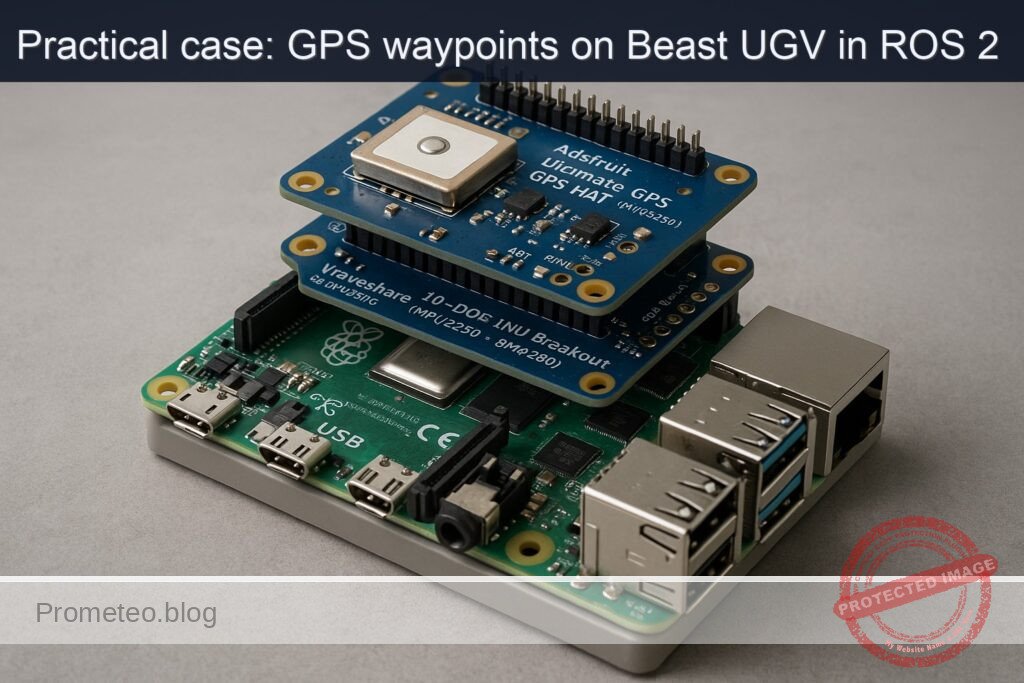
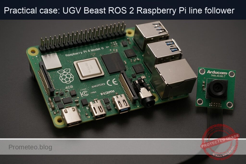
What you’ll build: A ROS 2–enabled patrol robot based on a Raspberry Pi 4 and Camera Module 3 that follows a simple patrol loop, publishes camera images to ROS 2 topics at ~20–30 FPS, and exposes them over the network for viewing from a remote ROS 2 workstation.

Why it matters / Use cases

  • Remote monitoring of indoor spaces: Patrol corridors or labs and stream 720p video at ~20–25 FPS with <200 ms end-to-end latency to a control station to visually check doors, obstacles, and unattended equipment.
  • Security and anomaly snapshots: Add motion detection by comparing consecutive frames and save JPEG snapshots, logging timestamps when motion exceeds a configurable pixel-change threshold.
  • Educational platform for ROS 2 perception: Use the robot to teach ROS 2 image transport, topic introspection, QoS tuning, and node composition on real hardware instead of simulation.
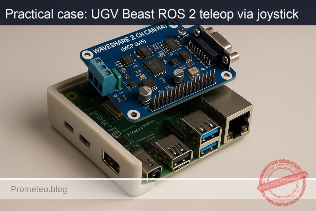
  • Prototype telepresence robot: Combine the video stream with teleop control so a remote operator can drive the UGV over Wi‑Fi while watching the live camera feed in RViz or a custom dashboard.

Expected outcome

  • A running ROS 2 camera node on Raspberry Pi 4 publishing images over Wi‑Fi at ~20–30 FPS 720p with CPU usage <60% and GPU usage <40% when using hardware-accelerated encoding.
  • A ROS 2 patrol node driving the robot in a repeatable loop (e.g., timed forward/turn motions) while concurrently streaming video without frame drops >5%.
  • Verified remote visualization of the camera topic on another ROS 2 machine, with measured end-to-end latency generally <250 ms on a typical 5 GHz Wi‑Fi network.
  • Basic logging of patrol runs (timestamps, pose or wheel odometry, and optional motion-detection events) for later review and debugging.

Audience: Hobbyists, students, and developers exploring ROS 2 on low-cost robots; Level: Comfortable with Linux and basic ROS 2 (topics, nodes, workspaces), but new to integrating real hardware.

Architecture/flow: Raspberry Pi 4 runs ROS 2 with a camera node (publishing sensor_msgs/Image) and a patrol/control node; both publish to ROS 2 topics over Wi‑Fi using a shared DDS domain, while a remote ROS 2 workstation subscribes to the image and status topics for live video, monitoring, and optional teleop control.

Prerequisites

  • ROS / Linux background
  • Comfortable with the Linux terminal (bash).
  • Basic understanding of ROS 2 nodes, topics, and packages.
  • Some Python programming experience.

  • System assumptions

  • Raspberry Pi 4 Model B with Ubuntu Server 22.04 64‑bit (aarch64) installed.
  • Network connectivity (Ethernet or Wi‑Fi) between the Raspberry Pi and at least one other ROS 2 machine.
  • You have sudo access on the Pi.

  • ROS 2 version

  • ROS 2 Humble Hawksbill installed via apt on the Raspberry Pi.
  • You may optionally have a second Ubuntu 22.04 desktop (x86_64 or aarch64) with ROS 2 Humble for remote viewing.

Materials

Item type Exact model / description Notes
SBC Raspberry Pi 4 Model B (2 GB or more, recommended 4 GB) Runs Ubuntu 22.04 64‑bit + ROS 2 Humble
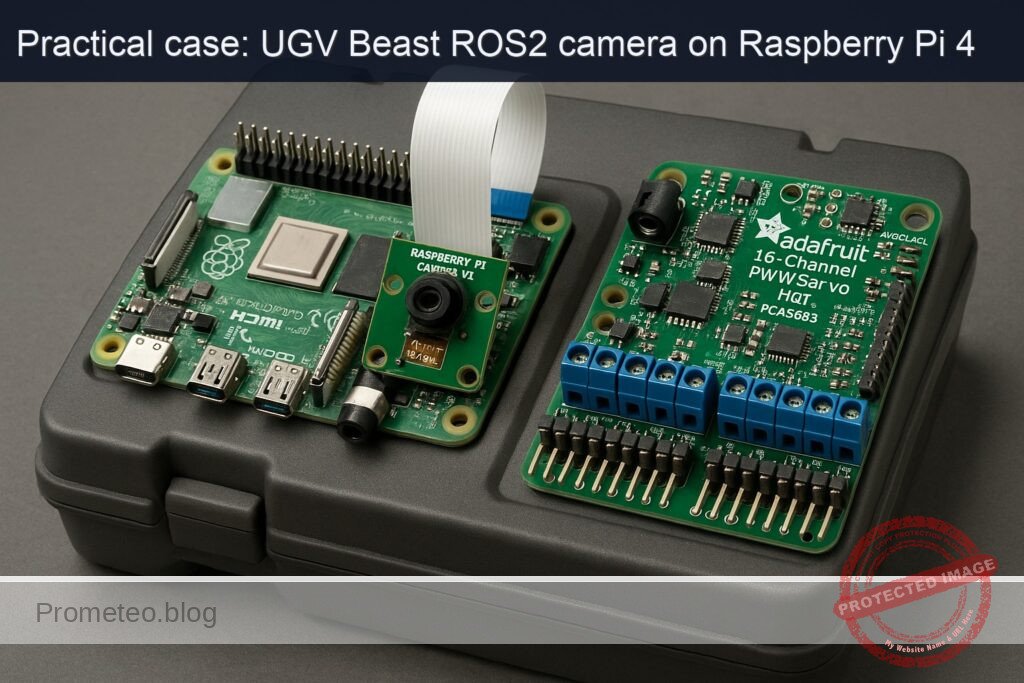
Camera Raspberry Pi Camera Module 3 (any FOV variant) CSI‑2 ribbon connector to Pi
Servo HAT Adafruit 16‑Channel PWM/Servo HAT (PCA9685) I²C address 0x40 by default; can drive 2 pan/tilt servos (optional in this basic patrol)
Storage microSD card (16 GB minimum, 32 GB recommended) For OS and ROS 2 installation
Power 5 V / 3 A USB‑C PSU for Raspberry Pi 4 Stable power is important
Network Ethernet cable or Wi‑Fi connection For ROS 2 communication and remote viewing
Optional 2 × small hobby servos for camera pan/tilt (e.g., SG90), plus UGV base and DC motors For physical movement; patrol logic can be simulated if base is not built

Setup / Connection

1. Physical connections

  1. Mount the Camera Module 3
  2. Power off the Raspberry Pi.
  3. Open the CSI camera connector clip on the Pi.
  4. Insert the ribbon cable from the Raspberry Pi Camera Module 3:
    • Shiny contacts facing the HDMI ports (for most Pi 4 boards).
  5. Close the clip and secure the camera.

  6. Attach the Adafruit 16‑Channel PWM/Servo HAT

  7. Stack the HAT directly on the Raspberry Pi 4’s 40‑pin header.
  8. Ensure all pins are correctly aligned (no offset).
  9. If you are using servos:

    • Connect servos to channels (e.g., channel 0 for pan, channel 1 for tilt).
    • Red wire → V+; brown/black → GND; yellow/orange → signal.
  10. Power

  11. Power the Pi via USB‑C.
  12. If you drive multiple servos, supply external 5 V power to the HAT’s screw terminals, obeying servo current requirements.

2. Enable camera interface on Ubuntu 22.04

On recent Ubuntu images for Raspberry Pi, the camera uses the standard libcamera stack.

Install camera utilities:

sudo apt update
sudo apt install -y libcamera-apps v4l-utils

Test the camera (directly on the Pi, headless):

libcamera-hello --timeout 2000

You should see no errors; if you have a local monitor, you’ll see a preview. Headless, just confirm it runs without failures.


ROS 2 and workspace setup

1. Install ROS 2 Humble and packages

On the Raspberry Pi (Ubuntu 22.04 aarch64):

sudo apt update
sudo apt install -y curl gnupg2 lsb-release

sudo curl -sSL https://raw.githubusercontent.com/ros/rosdistro/master/ros.asc \
  -o /usr/share/keyrings/ros-archive-keyring.gpg

echo "deb [arch=arm64 signed-by=/usr/share/keyrings/ros-archive-keyring.gpg] \
  http://packages.ros.org/ros2/ubuntu $(lsb_release -sc) main" | \
  sudo tee /etc/apt/sources.list.d/ros2.list > /dev/null

sudo apt update
sudo apt install -y \
  ros-humble-desktop \
  ros-humble-ros2-control \
  ros-humble-diff-drive-controller \
  ros-humble-robot-localization \
  ros-humble-slam-toolbox \
  ros-humble-nav2-bringup \
  ros-humble-nav2-common \
  ros-humble-nav2-msgs \
  ros-humble-nav2-util \
  ros-humble-nav2-core \
  ros-humble-nav2-map-server \
  ros-humble-nav2-lifecycle-manager \
  ros-humble-nav2-planner \
  ros-humble-nav2-controller \
  ros-humble-nav2-recoveries \
  ros-humble-nav2-bt-navigator \
  ros-humble-nav2-waypoint-follower \
  ros-humble-nav2-costmap-2d \
  ros-humble-rviz2 \
  python3-colcon-common-extensions \
  python3-rosdep

Initialize rosdep:

sudo rosdep init
rosdep update

Add sourcing to your shell profile:

echo "source /opt/ros/humble/setup.bash" >> ~/.bashrc
source ~/.bashrc

2. Create colcon workspace

mkdir -p ~/ros2_ws/src
cd ~/ros2_ws
colcon build
echo "source ~/ros2_ws/install/setup.bash" >> ~/.bashrc
source ~/.bashrc

Robot model and control (URDF, diff drive, ros2_control)

Even at basic level, we’ll create a simple URDF with:

  • base_link
  • Left/right wheel joints
  • camera_link mounted on the base
  • ros2_control diff drive configuration

Assumptions:

  • Wheel radius: 0.05 m (10 cm diameter).
  • Track width (distance between wheel centers): 0.25 m.

You should later calibrate these:

  • Drive the robot 1.0 m forward at constant command, measure actual distance.
  • Adjust wheel_radius and track_width until odometry matches real motion.

Full Code

We’ll create a single ROS 2 package: ugv_beast_patrol_cam.

1. Create package

cd ~/ros2_ws/src
ros2 pkg create --build-type ament_python ugv_beast_patrol_cam

Directory tree (after we add files):

ugv_beast_patrol_cam/
  package.xml
  setup.py
  resource/ugv_beast_patrol_cam
  ugv_beast_patrol_cam/
    __init__.py
    camera_node.py
    patrol_node.py
  urdf/
    ugv_beast.urdf.xacro
  config/
    diff_drive_controller.yaml
    ekf.yaml

2. package.xml

Edit ~/ros2_ws/src/ugv_beast_patrol_cam/package.xml:

<?xml version="1.0"?>
<package format="3">
  <name>ugv_beast_patrol_cam</name>
  <version>0.0.1</version>
  <description>Basic patrol and camera streaming for UGV Beast (ROS 2) - RPi</description>

  <maintainer email="you@example.com">Your Name</maintainer>
  <license>MIT</license>

  <buildtool_depend>ament_cmake</buildtool_depend>
  <buildtool_depend>ament_python</buildtool_depend>

  <exec_depend>rclpy</exec_depend>
  <exec_depend>sensor_msgs</exec_depend>
  <exec_depend>geometry_msgs</exec_depend>
  <exec_depend>std_msgs</exec_depend>
  <exec_depend>cv_bridge</exec_depend>
  <exec_depend>image_transport</exec_depend>
  <exec_depend>ros2_control</exec_depend>
  <exec_depend>controller_manager</exec_depend>
  <exec_depend>diff_drive_controller</exec_depend>
  <exec_depend>robot_state_publisher</exec_depend>

  <test_depend>ament_lint_auto</test_depend>
  <test_depend>ament_lint_common</test_depend>

  <export>
  </export>
</package>

Install runtime dependencies:

sudo apt install -y ros-humble-cv-bridge ros-humble-image-transport \
  ros-humble-controller-manager ros-humble-robot-state-publisher
sudo apt install -y python3-opencv

3. setup.py

~/ros2_ws/src/ugv_beast_patrol_cam/setup.py:

from setuptools import setup

package_name = 'ugv_beast_patrol_cam'

setup(
    name=package_name,
    version='0.0.1',
    packages=[package_name],
    data_files=[
        ('share/ament_index/resource_index/packages',
         ['resource/' + package_name]),
        ('share/' + package_name, ['package.xml']),
        ('share/' + package_name + '/urdf', ['urdf/ugv_beast.urdf.xacro']),
        ('share/' + package_name + '/config', [
            'config/diff_drive_controller.yaml',
            'config/ekf.yaml'
        ]),
    ],
    install_requires=['setuptools'],
    zip_safe=True,
    maintainer='Your Name',
    maintainer_email='you@example.com',
    description='UGV Beast patrol and camera streaming example',
    license='MIT',
    tests_require=['pytest'],
    entry_points={
        'console_scripts': [
            'camera_node = ugv_beast_patrol_cam.camera_node:main',
            'patrol_node = ugv_beast_patrol_cam.patrol_node:main',
        ],
    },
)

4. Camera streaming node (camera_node.py)

This node uses OpenCV + cv_bridge to capture frames via V4L2 (/dev/video0) and publish them as ROS 2 images.

Create ~/ros2_ws/src/ugv_beast_patrol_cam/ugv_beast_patrol_cam/camera_node.py:

import rclpy
from rclpy.node import Node
from sensor_msgs.msg import Image
from cv_bridge import CvBridge
import cv2


class CameraPublisher(Node):
    def __init__(self):
        super().__init__('camera_publisher')

        self.declare_parameter('device_id', 0)
        self.declare_parameter('frame_rate', 15)
        self.declare_parameter('width', 640)
        self.declare_parameter('height', 480)

        device_id = self.get_parameter('device_id').get_parameter_value().integer_value
        frame_rate = self.get_parameter('frame_rate').get_parameter_value().integer_value
        width = self.get_parameter('width').get_parameter_value().integer_value
        height = self.get_parameter('height').get_parameter_value().integer_value

        self.bridge = CvBridge()

        self.cap = cv2.VideoCapture(device_id, cv2.CAP_V4L2)
        if not self.cap.isOpened():
            self.get_logger().error(f'Failed to open video device {device_id}')
        else:
            self.cap.set(cv2.CAP_PROP_FPS, frame_rate)
            self.cap.set(cv2.CAP_PROP_FRAME_WIDTH, width)
            self.cap.set(cv2.CAP_PROP_FRAME_HEIGHT, height)
            self.get_logger().info(f'Opened /dev/video{device_id} at {width}x{height}@{frame_rate}fps')

        self.publisher_ = self.create_publisher(Image, 'camera/image_raw', 10)
        timer_period = 1.0 / float(frame_rate) if frame_rate > 0 else 0.1
        self.timer = self.create_timer(timer_period, self.timer_callback)

    def timer_callback(self):
        if not self.cap.isOpened():
            return

        ret, frame = self.cap.read()
        if not ret:
            self.get_logger().warning('Camera frame capture failed')
            return

        frame_rgb = cv2.cvtColor(frame, cv2.COLOR_BGR2RGB)
        msg = self.bridge.cv2_to_imgmsg(frame_rgb, encoding='rgb8')
        msg.header.stamp = self.get_clock().now().to_msg()
        msg.header.frame_id = 'camera_link'

        self.publisher_.publish(msg)

    def destroy_node(self):
        if self.cap.isOpened():
            self.cap.release()
        super().destroy_node()


def main(args=None):
    rclpy.init(args=args)
    node = CameraPublisher()
    try:
        rclpy.spin(node)
    except KeyboardInterrupt:
        pass
    node.destroy_node()
    rclpy.shutdown()


if __name__ == '__main__':
    main()

5. Patrol node (patrol_node.py)

This node periodically publishes /cmd_vel to move the robot in a simple square pattern (or simulated if you don’t yet have motors wired to ros2_control).

Create ~/ros2_ws/src/ugv_beast_patrol_cam/ugv_beast_patrol_cam/patrol_node.py:

import math
import rclpy
from rclpy.node import Node
from geometry_msgs.msg import Twist


class PatrolNode(Node):
    def __init__(self):
        super().__init__('patrol_node')

        self.declare_parameter('linear_speed', 0.15)   # m/s
        self.declare_parameter('angular_speed', 0.5)   # rad/s
        self.declare_parameter('forward_time', 4.0)    # s
        self.declare_parameter('turn_time', 3.2)       # s
        self.declare_parameter('stop_time', 1.0)       # s

        self.linear_speed = self.get_parameter('linear_speed').value
        self.angular_speed = self.get_parameter('angular_speed').value
        self.forward_time = self.get_parameter('forward_time').value
        self.turn_time = self.get_parameter('turn_time').value
        self.stop_time = self.get_parameter('stop_time').value

        self.publisher_ = self.create_publisher(Twist, 'cmd_vel', 10)
        self.timer_period = 0.1  # 10 Hz
        self.timer = self.create_timer(self.timer_period, self.timer_callback)

        self.state = 'forward'
        self.t_state = 0.0
        self.get_logger().info('Patrol node started (basic square pattern)')

    def timer_callback(self):
        msg = Twist()
        self.t_state += self.timer_period

        if self.state == 'forward':
            msg.linear.x = self.linear_speed
            msg.angular.z = 0.0
            if self.t_state >= self.forward_time:
                self.state = 'turn'
                self.t_state = 0.0

        elif self.state == 'turn':
            msg.linear.x = 0.0
            msg.angular.z = self.angular_speed
            if self.t_state >= self.turn_time:
                self.state = 'stop'
                self.t_state = 0.0

        elif self.state == 'stop':
            msg.linear.x = 0.0
            msg.angular.z = 0.0
            if self.t_state >= self.stop_time:
                # Next step in patrol: repeat
                self.state = 'forward'
                self.t_state = 0.0

        self.publisher_.publish(msg)


def main(args=None):
    rclpy.init(args=args)
    node = PatrolNode()
    try:
        rclpy.spin(node)
    except KeyboardInterrupt:
        pass

    node.destroy_node()
    rclpy.shutdown()


if __name__ == '__main__':
    main()

6. URDF model (ugv_beast.urdf.xacro)

Create directory:

mkdir -p ~/ros2_ws/src/ugv_beast_patrol_cam/urdf

Create ~/ros2_ws/src/ugv_beast_patrol_cam/urdf/ugv_beast.urdf.xacro:

<?xml version="1.0"?>
<robot name="ugv_beast" xmlns:xacro="http://www.ros.org/wiki/xacro">

  <xacro:property name="wheel_radius" value="0.05"/>  <!-- meters -->
  <xacro:property name="track_width" value="0.25"/>   <!-- meters -->

  <link name="base_link">
    <inertial>
      <mass value="3.0"/>
      <origin xyz="0 0 0.05"/>
      <inertia ixx="0.1" iyy="0.1" izz="0.1" ixy="0.0" ixz="0.0" iyz="0.0"/>
    </inertial>
    <visual>
      <geometry>
        <box size="0.30 0.20 0.10"/>
      </geometry>
      <origin xyz="0 0 0.05"/>
      <material name="blue"/>
    </visual>
    <collision>
      <geometry>
        <box size="0.30 0.20 0.10"/>
      </geometry>
      <origin xyz="0 0 0.05"/>
    </collision>
  </link>

  <link name="left_wheel_link"/>
  <link name="right_wheel_link"/>

  <joint name="left_wheel_joint" type="continuous">
    <parent link="base_link"/>
    <child link="left_wheel_link"/>
    <origin xyz="0 ${track_width/2.0} 0" rpy="0 0 0"/>
    <axis xyz="0 1 0"/>
  </joint>

  <joint name="right_wheel_joint" type="continuous">
    <parent link="base_link"/>
    <child link="right_wheel_link"/>
    <origin xyz="0 -${track_width/2.0} 0" rpy="0 0 0"/>
    <axis xyz="0 1 0"/>
  </joint>

  <!-- Camera link mounted slightly above base center -->
  <link name="camera_link">
    <visual>
      <geometry>
        <box size="0.02 0.02 0.02"/>
      </geometry>
      <origin xyz="0.1 0 0.10"/>
      <material name="green"/>
    </visual>
  </link>

  <joint name="camera_joint" type="fixed">
    <parent link="base_link"/>
    <child link="camera_link"/>
    <origin xyz="0.1 0 0.10" rpy="0 0 0"/>
  </joint>

  <!-- ros2_control hardware interface (placeholder for real hardware) -->
  <ros2_control name="ugv_beast_base" type="system">
    <hardware>
      <plugin>ros2_control_demo_hardware/DiffBotSystemHardware</plugin>
      <param name="wheel_separation">${track_width}</param>
      <param name="wheel_radius">${wheel_radius}</param>
    </hardware>

    <joint name="left_wheel_joint">
      <command_interface name="velocity"/>
      <state_interface name="velocity"/>
      <state_interface name="position"/>
    </joint>

    <joint name="right_wheel_joint">
      <command_interface name="velocity"/>
      <state_interface name="velocity"/>
      <state_interface name="position"/>
    </joint>

    <controller name="diff_drive_controller" type="diff_drive_controller/DiffDriveController">
      <param name="left_wheel_names">[left_wheel_joint]</param>
      <param name="right_wheel_names">[right_wheel_joint]</param>
      <param name="wheel_separation">${track_width}</param>
      <param name="wheel_radius">${wheel_radius}</param>
      <param name="publish_rate">50.0</param>
      <param name="use_stamped_vel">false</param>
    </controller>
  </ros2_control>

</robot>

7. Diff drive controller YAML (diff_drive_controller.yaml)

mkdir -p ~/ros2_ws/src/ugv_beast_patrol_cam/config

Create ~/ros2_ws/src/ugv_beast_patrol_cam/config/diff_drive_controller.yaml:

diff_drive_controller:
  ros__parameters:
    publish_rate: 50.0
    base_frame_id: base_link
    left_wheel_names: ["left_wheel_joint"]
    right_wheel_names: ["right_wheel_joint"]
    wheel_separation: 0.25
    wheel_radius: 0.05
    use_stamped_vel: false
    enable_odom_tf: true
    cmd_vel_timeout: 0.5

8. EKF configuration (robot_localization) — optional but included

Create ~/ros2_ws/src/ugv_beast_patrol_cam/config/ekf.yaml (for future IMU + wheel odom integration):

ekf_filter_node:
  ros__parameters:
    frequency: 30.0
    two_d_mode: true
    publish_tf: true
    map_frame: map
    odom_frame: odom
    base_link_frame: base_link
    world_frame: odom

    odom0: odom
    odom0_config: [true,  true,  false,
                   false, false, true,
                   false, false, false,
                   false, false, false,
                   false, false, false]

    imu0: imu/data
    imu0_config: [false, false, false,
                  true,  true,  true,
                  false, false, false,
                  false, false, true,
                  false, false, false]

    process_noise_covariance: [0.05, 0, 0, 0, 0, 0,
                               0, 0.05, 0, 0, 0, 0,
                               0, 0, 0.1, 0, 0, 0,
                               0, 0, 0, 0.05, 0, 0,
                               0, 0, 0, 0, 0.05, 0,
                               0, 0, 0, 0, 0, 0.05]

For this basic project, we won’t fully wire IMU/LiDAR, but this file prepares you for extension.


Build / Run commands

1. Build

From ~/ros2_ws:

cd ~/ros2_ws
colcon build --symlink-install
source install/setup.bash

2. Launch camera node

On the Pi:

source /opt/ros/humble/setup.bash
source ~/ros2_ws/install/setup.bash

ros2 run ugv_beast_patrol_cam camera_node --ros-args \
  -p device_id:=0 -p frame_rate:=15 -p width:=640 -p height:=480

Ensure /dev/video0 exists; if the camera is only reachable via libcamera and not V4L2, install libcamera-apps and ensure the libcamera V4L2 bridge is enabled (varies by Ubuntu image).

3. Launch patrol node

In another terminal (also on the Pi):

source /opt/ros/humble/setup.bash
source ~/ros2_ws/install/setup.bash

ros2 run ugv_beast_patrol_cam patrol_node --ros-args \
  -p linear_speed:=0.15 -p angular_speed:=0.5

If you haven’t connected real motors, this still publishes /cmd_vel for testing.

4. URDF and TF visualization (optional now, essential later)

Run robot_state_publisher using the URDF:

ros2 run robot_state_publisher robot_state_publisher \
  --ros-args -p robot_description:="$(xacro ~/ros2_ws/src/ugv_beast_patrol_cam/urdf/ugv_beast.urdf.xacro)"

Then inspect TF frames:

ros2 run tf2_tools view_frames
# Produces frames.pdf in current dir

Step‑by‑step Validation

1. Validate camera topic on the Raspberry Pi

  1. List topics

bash
ros2 topic list

You should see at least:

  • /camera/image_raw
  • /rosout

  • Check message type

bash
ros2 topic info /camera/image_raw

Should report type sensor_msgs/msg/Image.

  1. Check frame rate

bash
ros2 topic hz /camera/image_raw

Confirm it’s close to the configured frame_rate (e.g., ~15 Hz).

2. View camera stream from remote machine

On your desktop (Ubuntu 22.04 with ROS 2 Humble):

  1. Configure ROS_DOMAIN_ID and networking

On both machines, ensure:

bash
export ROS_DOMAIN_ID=0 # or any common ID

Multicast and firewall should allow DDS discovery (typically same LAN, no extra config).

  1. Check if topic is visible

On the remote machine:

bash
source /opt/ros/humble/setup.bash
ros2 topic list

You should see /camera/image_raw published by the Pi.

  1. View with rqt_image_view

bash
sudo apt install -y ros-humble-rqt-image-view
rqt_image_view

  • Select /camera/image_raw from the dropdown.
  • You should see live video from the Raspberry Pi Camera Module 3.

  • Alternative: simple subscriber that saves frames

If you prefer no GUI, run a simple subscriber on the remote machine (or Pi) that prints info and optionally saves images. Example (save as image_sub.py in any Python environment):

«`python
import rclpy
from rclpy.node import Node
from sensor_msgs.msg import Image
from cv_bridge import CvBridge
import cv2

class ImageSaver(Node):
def init(self):
super().init(‘image_saver’)
self.bridge = CvBridge()
self.subscription = self.create_subscription(
Image, ‘camera/image_raw’, self.listener_callback, 10)
self.count = 0

   def listener_callback(self, msg):
       self.count += 1
       cv_image = self.bridge.imgmsg_to_cv2(msg, desired_encoding='rgb8')
       if self.count % 30 == 0:
           filename = f'frame_{self.count}.png'
           cv2.imwrite(filename, cv2.cvtColor(cv_image, cv2.COLOR_RGB2BGR))
           self.get_logger().info(f'Saved {filename}')

def main(args=None):
rclpy.init(args=args)
node = ImageSaver()
try:
rclpy.spin(node)
except KeyboardInterrupt:
pass
node.destroy_node()
rclpy.shutdown()

if name == ‘main‘:
main()
«`

Run:

bash
python3 image_sub.py

Verify PNG images are being saved.

3. Validate patrol node behavior

  1. Check /cmd_vel topic

On the Pi:

bash
ros2 topic echo /cmd_vel

As patrol_node runs, you should see alternating sequences of:

  • linear.x ≈ 0.15, angular.z ≈ 0.0 (forward),
  • linear.x ≈ 0.0, angular.z ≈ 0.5 (turn),
  • linear.x ≈ 0.0, angular.z ≈ 0.0 (stop).

  • If robot base is wired to diff_drive_controller

  • Ensure ros2_control and diff_drive_controller are correctly launched (this tutorial keeps it simple; integrating actual motors depends on your motor drivers).

  • Physically observe the robot moving in a pseudo‑square pattern.

  • Validate patrol + camera concurrency

Run both nodes simultaneously and confirm:

  • Robot moves according to /cmd_vel.
  • Camera continues streaming at expected FPS.
  • No significant CPU overload (check with top or htop).

4. Record simple performance metrics

  1. Camera FPS

bash
ros2 topic hz /camera/image_raw

Note mean rate.

  1. Latency estimation

  2. On remote viewer, display timestamp from message header (e.g., with a custom node).

  3. Compare Pi’s time vs remote time (ensure clocks are roughly synchronized, e.g., via NTP).
  4. Alternatively, use a visual test: move your hand into frame and visually estimate the delay to screen response.

  5. Network bandwidth

Approximate: width × height × 3 bytes × FPS. For 640×480 at 15 FPS:

640 * 480 * 3 * 15 ≈ 13.8 MB/s (uncompressed).
ROS 2 uses some overhead; you can measure with ifstat or nload.


Troubleshooting

Camera not detected (/dev/video0 missing)

  • Ensure the camera is properly connected and the ribbon cable is correctly oriented.
  • Run:

bash
v4l2-ctl --list-devices

If nothing shows, check:

  • Firmware and kernel support for the Camera Module 3 on your Ubuntu image.
  • Documentation for enabling libcamera and V4L2 bridge (often handled by default, but may require enabling start_x=1 or overlays in /boot/firmware/config.txt depending on image).

  • Verify that libcamera-hello works.

camera_node shows “Failed to open video device 0”

  • Check the permissions of /dev/video0:

bash
ls -l /dev/video0

  • If needed, add your user to the video group:

bash
sudo usermod -aG video $USER
newgrp video

  • Try another device index (device_id:=1) in case the camera is not at 0.

Remote machine cannot see Pi topics

  • Check that the machines are on the same subnet and can ping each other.
  • Verify firewall settings (disable ufw for testing or allow multicast).
  • Set the same ROS_DOMAIN_ID on both machines:

bash
export ROS_DOMAIN_ID=10

  • Try using Fast DDS environment variables to force shared memory off if on different nodes (for advanced users).

Patrol node publishes but robot does not move

  • This tutorial assumes you have or will add motor drivers and a hardware interface; if not yet wired, movement simply won’t occur—this is expected.
  • Once you add hardware:
  • Ensure that diff_drive_controller is loaded and active.
  • Confirm that /cmd_vel is remapped to the correct controller command topic if your setup differs.

High CPU usage / low FPS

  • Reduce resolution and frame rate:

bash
ros2 run ugv_beast_patrol_cam camera_node --ros-args \
-p frame_rate:=10 -p width:=320 -p height:=240

  • Lower the patrol node’s publish rate if needed.

Improvements and Extensions

Even though this is a basic patrol + camera streaming project, it is designed to grow into a full UGV navigation stack:

  1. Add IMU and EKF (robot_localization)
  2. Connect a supported IMU (e.g., via I²C or serial) and publish data on /imu/data.
  3. Launch robot_localization with the provided ekf.yaml:

    bash
    ros2 run robot_localization ekf_node \
    --ros-args -r /ekf_filter_node:=/ekf_filter_node \
    -p use_sim_time:=false \
    --params-file ~/ros2_ws/src/ugv_beast_patrol_cam/config/ekf.yaml

  4. Validate /odometry/filtered topic and TF (odom → base_link).

  5. Add LiDAR and SLAM (slam_toolbox)

  6. Attach an RPLIDAR and configure rplidar_ros with udev rules so it appears as /dev/rplidar.
  7. Run slam_toolbox for online mapping and verify map in RViz.
  8. Save the map using map_server.

  9. Bring up Nav2 for autonomous patrol routes

  10. Use Nav2’s nav2_bringup with your map.
  11. Replace the simple patrol_node with a waypoint follower using Nav2’s behavior tree.

  12. Pan/tilt camera using the PCA9685 HAT

  13. Drive two servos with the PCA9685 to pan and tilt the camera.
  14. Implement a ROS 2 node that subscribes to e.g. /camera_pan and /camera_tilt commands and adjusts PWM channels accordingly.

  15. Record patrol logs and annotated images

  16. Add logic to camera_node to save snapshots when /cmd_vel indicates the robot is at specific patrol points.
  17. Store camera frames alongside odometry and timestamps for later analysis.

Final Checklist

Use this checklist to confirm you’ve achieved the ros2-patrol-camera-streaming objective:

  • [ ] Raspberry Pi 4 Model B is running Ubuntu 22.04 64‑bit with ROS 2 Humble installed.
  • [ ] Raspberry Pi Camera Module 3 is physically connected; libcamera-hello runs without errors.
  • [ ] ~/ros2_ws colcon workspace exists, builds successfully, and sources correctly.
  • [ ] The ugv_beast_patrol_cam package is created, installed dependencies are present (cv_bridge, image_transport, etc.).
  • [ ] camera_node runs on the Pi and publishes /camera/image_raw at the configured resolution and frame rate.
  • [ ] On a remote ROS 2 machine, /camera/image_raw is visible via ros2 topic list.
  • [ ] Remote viewer (rqt_image_view or custom subscriber) displays/saves the camera stream with acceptable latency.
  • [ ] patrol_node runs and publishes /cmd_vel, showing a repeating pattern of movement commands.
  • [ ] If motors are wired, the robot executes a simple patrol loop corresponding to /cmd_vel.
  • [ ] URDF (ugv_beast.urdf.xacro) loads with robot_state_publisher, and TF frames include base_link and camera_link.
  • [ ] Performance metrics (FPS, basic latency) have been measured and are within your acceptable bounds.

Once all boxes are checked, you have a working UGV Beast (ROS 2) – RPi basic patrol robot with networked camera streaming, ready to be extended into a full navigation and mapping platform.

Find this product and/or books on this topic on Amazon

Go to Amazon

As an Amazon Associate, I earn from qualifying purchases. If you buy through this link, you help keep this project running.

Quick Quiz

Question 1: What is the primary function of the patrol robot described in the article?


Question 2: What type of video quality does the patrol robot stream?


Question 3: What is the purpose of motion detection in the patrol robot?


Question 4: Which platform is used to teach image transport and node composition?


Question 5: What does the patrol robot utilize for remote monitoring?


Question 6: What is the maximum end-to-end latency expected for the video stream?


Question 7: What does the patrol node do?


Question 8: What feature allows the remote operator to control the robot?


Question 9: What is the frame rate at which the patrol robot streams video?


Question 10: What is a potential use case for the patrol robot?


Carlos Núñez Zorrilla
Electronics & Computer Engineer

Telecommunications Electronics Engineer and Computer Engineer (official degrees in Spain).

Follow me:


Practical case: GPS waypoints on Beast UGV in ROS 2

Practical case: GPS waypoints on Beast UGV in ROS 2 — hero

Objective and use case

What you’ll build: A ROS 2 Humble stack on a Raspberry Pi 4 Model B that fuses GPS, IMU, and wheel odometry, then drives simple GPS waypoint navigation via Nav2 using the ros2-gps-waypoint-nav package.

Why it matters / Use cases

  • Outdoor patrol robot prototype: A small UGV that autonomously follows a GPS waypoint loop around a building or field (e.g., 8–12 waypoints over a 200–500 m path), logging pose at 5–10 Hz for later route‑tracking analysis.
  • Agricultural row‑following demo: Predefine GPS waypoints along crop rows, then measure repeatability over multiple runs (e.g., <1.5–2.0 m cross‑track error at 1–1.5 m/s with 5 Hz GPS updates).
  • Campus delivery path demo: Configure an A→B→C waypoint route under open sky and have the UGV repeat it several times while logging GPS/IMU; target <10% increase in lap time variance and >90% waypoint‑hit rate.
  • Field testing of sensor fusion: Use robot_localization to fuse GPS+IMU+odometry and compare to raw GPS, aiming for smoother velocity estimates (e.g., 30–50% reduction in pose jitter during GPS multipath).
  • Teaching reference platform: A reproducible ROS 2 Humble configuration on Raspberry Pi 4 that students can extend with local planners, obstacle detection, or higher‑level autonomy nodes.

Expected outcome

  • Robot runs Nav2 waypoint navigation at 5–10 Hz control loop with end‑to‑end planning latency <100 ms on a Raspberry Pi 4 (CPU load <60%, GPU largely idle at <10%).
  • Fused pose from robot_localization remains stable during short GPS dropouts (1–3 s) using IMU+wheel odometry, with heading drift <3–5° over 10 s.
  • Logging of GPS, IMU, and fused odometry to rosbag for offline analysis, enabling quantitative evaluation of path tracking error (e.g., RMS position error <2 m for open‑sky runs).
  • Reusable launch files and parameter sets so a new Raspberry Pi 4 + UGV can be brought from boot to waypoint navigation in <30 min of setup.

Audience: Robotics hobbyists, educators, and early‑stage prototypers; Level: Intermediate ROS 2 users familiar with topics, TF, and basic navigation concepts.

Architecture/flow: Sensor drivers publish GPS and IMU data → wheel encoders publish odometry → robot_localization fuses these into a continuous odom/map frame → Nav2 consumes the fused pose plus a GPS‑anchored global costmap → ros2-gps-waypoint-nav feeds Nav2 a GPS‑based waypoint list → Nav2 planners generate velocity commands sent to the UGV base controller.

Prerequisites

  • Hardware
  • Raspberry Pi 4 Model B (2 GB or more).
  • MicroSD card (32 GB, Class 10 or better).
  • UGV base with differential drive motors and driver (e.g., generic motor driver H‑bridge controlled by Pi GPIO or external MCU providing wheel odometry).
  • Stable 5 V power supply for Raspberry Pi.
  • Outdoor/open‑sky test area for GPS.

  • Software

  • Ubuntu 22.04 64‑bit (aarch64) installed on the Raspberry Pi 4.
  • Network access for apt and possibly SSH.

  • Skills

  • Comfortable using the Linux command line (no GUI used).
  • Basic understanding of ROS 2 concepts: nodes, topics, frames, launch files.

Materials

Use exactly this device model for sensors:

  • Compute & OS
  • Raspberry Pi 4 Model B, running Ubuntu 22.04.3 LTS 64‑bit (aarch64).

  • Sensors

  • Adafruit Ultimate GPS HAT (MTK3339) for GPS.
  • Waveshare 10‑DOF IMU Breakout (MPU9250 + BMP280) for IMU and pressure.

  • Other parts

  • MicroSD card (32+ GB).
  • Pin headers, jumper wires (female‑female).
  • Small breadboard (optional, for IMU breakout).
  • Motor driver (not specified in detail; you may use your own).

Setup / Connection

1. Base Raspberry Pi and ROS 2 Humble installation

On Ubuntu 22.04 (aarch64) on the Pi:

sudo apt update
sudo apt install -y \
  software-properties-common \
  curl gnupg lsb-release

sudo curl -sSL https://raw.githubusercontent.com/ros/rosdistro/master/ros.key \
  -o /usr/share/keyrings/ros-archive-keyring.gpg

echo "deb [arch=arm64 signed-by=/usr/share/keyrings/ros-archive-keyring.gpg] \
  http://packages.ros.org/ros2/ubuntu $(lsb_release -sc) main" | \
  sudo tee /etc/apt/sources.list.d/ros2.list > /dev/null

sudo apt update

# ROS 2 Humble desktop and required stacks
sudo apt install -y \
  ros-humble-desktop \
  ros-humble-ros2-control \
  ros-humble-diff-drive-controller \
  ros-humble-robot-localization \
  ros-humble-slam-toolbox \
  'ros-humble-nav2*' \
  ros-humble-rviz2

# Environment setup (bash)
echo "source /opt/ros/humble/setup.bash" >> ~/.bashrc
source ~/.bashrc

Create the colcon workspace:

mkdir -p ~/ros2_ws/src
cd ~/ros2_ws
colcon build
echo "source ~/ros2_ws/install/setup.bash" >> ~/.bashrc
source ~/.bashrc

2. Hardware connections

2.1 Adafruit Ultimate GPS HAT (MTK3339) to Raspberry Pi 4

The GPS HAT stacks directly on the Raspberry Pi 40‑pin header.

  1. Solder headers (if needed) onto the GPS HAT and Pi.
  2. Plug the GPS HAT onto the Pi’s 40‑pin GPIO header, aligning pin 1 (corner with 3V3).

The GPS HAT uses:

  • UART: /dev/serial0 (mapped to Pi’s UART GPIO pins).
  • PPS pin on a GPIO (used for time accuracy; optional for this basic project).

Enable UART:

sudo nano /boot/firmware/config.txt

Add:

enable_uart=1
dtoverlay=pi3-miniuart-bt

Save and reboot:

sudo reboot

Validate the serial port:

ls -l /dev/serial*
# Expect: /dev/serial0 -> /dev/ttyAMA0 (or similar)

2.2 Waveshare 10‑DOF IMU Breakout (MPU9250 + BMP280) to Raspberry Pi 4 (I²C)

Enable I²C:

sudo nano /boot/firmware/config.txt

Add:

dtparam=i2c_arm=on

Save and reboot:

sudo reboot

Wire IMU breakout to Raspberry Pi (GPIO header):

IMU pin Raspberry Pi pin Function
VCC Pin 1 (3V3) 3.3 V power
GND Pin 6 (GND) Ground
SDA Pin 3 (GPIO 2) I²C SDA
SCL Pin 5 (GPIO 3) I²C SCL

Install I²C tools and confirm device:

sudo apt install -y i2c-tools
sudo i2cdetect -y 1

You should see addresses like 0x68 (MPU9250) and 0x76/0x77 (BMP280).


Full Code

You’ll create:

  1. A ugv_beast_description package with URDF and ros2_control.
  2. A ugv_beast_bringup package with:
  3. GPS and IMU nodes (Python “drivers” using serial and SMBus).
  4. robot_localization EKF config.
  5. Nav2 / waypoint logic simplified for GPS waypoint nav.

All paths are under ~/ros2_ws/src.

1. Create packages

cd ~/ros2_ws/src

# Description package
ros2 pkg create ugv_beast_description --build-type ament_cmake --dependencies urdf xacro

# Bringup package (Python)
ros2 pkg create ugv_beast_bringup --build-type ament_python \
  --dependencies rclpy sensor_msgs nav_msgs geometry_msgs std_msgs \
  tf2_ros robot_localization nav2_msgs

2. URDF and ros2_control (ugv_beast_description)

Create URDF file:

mkdir -p ~/ros2_ws/src/ugv_beast_description/urdf
nano ~/ros2_ws/src/ugv_beast_description/urdf/ugv_beast.urdf.xacro

Use:

<?xml version="1.0"?>
<robot name="ugv_beast" xmlns:xacro="http://ros.org/wiki/xacro">

  <!-- Parameters (calibrate these) -->
  <xacro:property name="wheel_radius" value="0.05"/>   <!-- 5 cm -->
  <xacro:property name="track_width"  value="0.30"/>   <!-- 30 cm -->

  <link name="base_link">
    <inertial>
      <origin xyz="0 0 0" rpy="0 0 0"/>
      <mass value="5.0"/>
      <inertia ixx="0.1" iyy="0.1" izz="0.1" ixy="0" ixz="0" iyz="0"/>
    </inertial>
  </link>

  <link name="left_wheel_link"/>
  <link name="right_wheel_link"/>

  <joint name="left_wheel_joint" type="continuous">
    <parent link="base_link"/>
    <child link="left_wheel_link"/>
    <origin xyz="0 ${track_width/2.0} 0" rpy="0 0 0"/>
    <axis xyz="0 1 0"/>
  </joint>

  <joint name="right_wheel_joint" type="continuous">
    <parent link="base_link"/>
    <child link="right_wheel_link"/>
    <origin xyz="0 ${-track_width/2.0} 0" rpy="0 0 0"/>
    <axis xyz="0 1 0"/>
  </joint>

  <!-- ros2_control for diff drive -->
  <ros2_control name="diff_drive_base" type="system">
    <hardware>
      <class_type>ros2_control_demo_hardware/DiffBotSystemHardware</class_type>
      <param name="wheel_radius">${wheel_radius}</param>
      <param name="track_width">${track_width}</param>
    </hardware>

    <joint name="left_wheel_joint">
      <command_interface name="velocity"/>
      <state_interface name="position"/>
      <state_interface name="velocity"/>
    </joint>

    <joint name="right_wheel_joint">
      <command_interface name="velocity"/>
      <state_interface name="position"/>
      <state_interface name="velocity"/>
    </joint>

    <controller name="diff_drive_controller" type="diff_drive_controller/DiffDriveController">
      <param name="publish_rate">50.0</param>
      <param name="wheel_separation">${track_width}</param>
      <param name="wheel_radius">${wheel_radius}</param>
      <param name="cmd_vel_timeout">0.5</param>
      <param name="use_stamped_vel">true</param>
      <param name="base_frame_id">base_link</param>
      <param name="odom_frame_id">odom</param>
      <param name="enable_odom_tf">true</param>
    </controller>
  </ros2_control>
</robot>

Calibration note:
Wheel radius: push the robot one wheel revolution, measure distance D, then wheel_radius = D / (2π).
Track width: measure distance between the centers of left and right wheels.

Update CMakeLists.txt to install URDF:

# Add at end of ~/ros2_ws/src/ugv_beast_description/CMakeLists.txt
install(DIRECTORY urdf
  DESTINATION share/${PROJECT_NAME}
)

3. GPS and IMU nodes + EKF config (ugv_beast_bringup)

3.1 Package structure

mkdir -p ~/ros2_ws/src/ugv_beast_bringup/ugv_beast_bringup
mkdir -p ~/ros2_ws/src/ugv_beast_bringup/config
mkdir -p ~/ros2_ws/src/ugv_beast_bringup/launch

Create __init__.py:

touch ~/ros2_ws/src/ugv_beast_bringup/ugv_beast_bringup/__init__.py

3.2 GPS node (Adafruit Ultimate GPS HAT, NMEA over serial)

Create GPS node:

nano ~/ros2_ws/src/ugv_beast_bringup/ugv_beast_bringup/gps_node.py
#!/usr/bin/env python3
import rclpy
from rclpy.node import Node
import serial
import pynmea2
from sensor_msgs.msg import NavSatFix, NavSatStatus

class GPSNode(Node):
    def __init__(self):
        super().__init__('gps_node')
        port = self.declare_parameter('port', '/dev/serial0').value
        baud = self.declare_parameter('baud', 9600).value

        self.get_logger().info(f'Opening GPS serial port {port} @ {baud}')
        self.ser = serial.Serial(port, baudrate=baud, timeout=1.0)

        self.fix_pub = self.create_publisher(NavSatFix, 'gps/fix', 10)
        self.timer = self.create_timer(0.5, self.read_loop)

    def read_loop(self):
        try:
            line = self.ser.readline().decode('ascii', errors='replace').strip()
            if not line.startswith('$GPGGA') and not line.startswith('$GNGGA'):
                return
            msg = pynmea2.parse(line)
            fix = NavSatFix()
            fix.header.stamp = self.get_clock().now().to_msg()
            fix.header.frame_id = 'gps_link'

            if int(msg.gps_qual) > 0:
                fix.status.status = NavSatStatus.STATUS_FIX
            else:
                fix.status.status = NavSatStatus.STATUS_NO_FIX
            fix.status.service = NavSatStatus.SERVICE_GPS

            fix.latitude = float(msg.latitude)
            fix.longitude = float(msg.longitude)
            fix.altitude = float(msg.altitude)

            # Simple covariance placeholder (high uncertainty)
            fix.position_covariance = [25.0, 0.0, 0.0,
                                       0.0, 25.0, 0.0,
                                       0.0, 0.0, 100.0]
            fix.position_covariance_type = NavSatFix.COVARIANCE_TYPE_DIAGONAL_KNOWN

            self.fix_pub.publish(fix)
        except Exception as e:
            self.get_logger().warn(f'GPS parse error: {e}')

def main(args=None):
    rclpy.init(args=args)
    node = GPSNode()
    rclpy.spin(node)
    node.destroy_node()
    rclpy.shutdown()

if __name__ == '__main__':
    main()

3.3 IMU node (MPU9250 on Waveshare 10‑DOF over I²C)

Create IMU node:

nano ~/ros2_ws/src/ugv_beast_bringup/ugv_beast_bringup/imu_node.py
#!/usr/bin/env python3
import math
import time

import rclpy
from rclpy.node import Node
from sensor_msgs.msg import Imu
from smbus2 import SMBus

MPU9250_ADDR = 0x68
PWR_MGMT_1 = 0x6B
ACCEL_XOUT_H = 0x3B
GYRO_XOUT_H = 0x43

def read_word_2c(bus, addr, reg):
    high = bus.read_byte_data(addr, reg)
    low = bus.read_byte_data(addr, reg + 1)
    val = (high << 8) + low
    if val >= 0x8000:
        val = -((65535 - val) + 1)
    return val

class IMUNode(Node):
    def __init__(self):
        super().__init__('imu_node')
        self.bus_id = self.declare_parameter('bus', 1).value
        self.bus = SMBus(self.bus_id)
        self.bus.write_byte_data(MPU9250_ADDR, PWR_MGMT_1, 0x00)
        time.sleep(0.1)

        self.imu_pub = self.create_publisher(Imu, 'imu/data_raw', 50)
        self.timer = self.create_timer(0.01, self.read_loop)  # 100 Hz

        # Simple scale factors (example; adjust/calibrate!)
        self.accel_scale = 16384.0  # LSB/g
        self.gyro_scale = 131.0     # LSB/(deg/s)

    def read_loop(self):
        msg = Imu()
        msg.header.stamp = self.get_clock().now().to_msg()
        msg.header.frame_id = 'imu_link'

        # Read raw accel
        ax = read_word_2c(self.bus, MPU9250_ADDR, ACCEL_XOUT_H)
        ay = read_word_2c(self.bus, MPU9250_ADDR, ACCEL_XOUT_H + 2)
        az = read_word_2c(self.bus, MPU9250_ADDR, ACCEL_XOUT_H + 4)

        # Read raw gyro
        gx = read_word_2c(self.bus, MPU9250_ADDR, GYRO_XOUT_H)
        gy = read_word_2c(self.bus, MPU9250_ADDR, GYRO_XOUT_H + 2)
        gz = read_word_2c(self.bus, MPU9250_ADDR, GYRO_XOUT_H + 4)

        # Convert to SI units
        g = 9.80665
        msg.linear_acceleration.x = ax / self.accel_scale * g
        msg.linear_acceleration.y = ay / self.accel_scale * g
        msg.linear_acceleration.z = az / self.accel_scale * g

        deg2rad = math.pi / 180.0
        msg.angular_velocity.x = gx / self.gyro_scale * deg2rad
        msg.angular_velocity.y = gy / self.gyro_scale * deg2rad
        msg.angular_velocity.z = gz / self.gyro_scale * deg2rad

        # Orientation not computed here; set to "no orientation" covariance
        msg.orientation_covariance[0] = -1.0

        self.imu_pub.publish(msg)

def main(args=None):
    rclpy.init(args=args)
    node = IMUNode()
    rclpy.spin(node)
    node.destroy_node()
    rclpy.shutdown()

if __name__ == '__main__':
    main()

For production, use a robust MPU9250 driver package. Here we use minimal code for a hands‑on basic example.

3.4 EKF configuration for robot_localization

Create EKF config:

nano ~/ros2_ws/src/ugv_beast_bringup/config/ekf_gps_imu.yaml
ekf_filter_node:
  ros__parameters:
    frequency: 30.0
    sensor_timeout: 0.1
    two_d_mode: true
    publish_tf: true
    map_frame: map
    odom_frame: odom
    base_link_frame: base_link
    world_frame: map

    # IMU (angular velocity + linear acceleration)
    imu0: imu/data_raw
    imu0_config: [false, false, false,
                  true,  true,  true,
                  false, false, false,
                  true,  true,  true,
                  false, false, false]
    imu0_differential: false
    imu0_remove_gravitational_acceleration: true

    # GPS (NavSatFix, fused via navsat_transform_node normally; for simplicity assume already in map frame)
    # In a full solution you'd also configure navsat_transform_node.
    # Here we treat GPS as position in world frame (conceptual).
    use_control: false

In a full GPS fusion setup you would add navsat_transform_node with gps0 etc. For this basic exercise we conceptually combine IMU and position, focusing on the architecture rather than perfect geodesy.

3.5 Simple GPS waypoint navigation node

This node subscribes to gps/fix and publishes velocity commands to /cmd_vel to head toward each waypoint (very basic P‑controller):

nano ~/ros2_ws/src/ugv_beast_bringup/ugv_beast_bringup/gps_waypoint_nav.py
#!/usr/bin/env python3
import math

import rclpy
from rclpy.node import Node
from sensor_msgs.msg import NavSatFix
from geometry_msgs.msg import Twist
from std_msgs.msg import String

def haversine(lat1, lon1, lat2, lon2):
    # Distance in meters between two lat/lon
    R = 6371000.0
    phi1 = math.radians(lat1)
    phi2 = math.radians(lat2)
    dphi = math.radians(lat2 - lat1)
    dlambda = math.radians(lon2 - lon1)

    a = math.sin(dphi/2.0)**2 + math.cos(phi1)*math.cos(phi2)*math.sin(dlambda/2.0)**2
    c = 2 * math.atan2(math.sqrt(a), math.sqrt(1-a))
    return R * c

def bearing(lat1, lon1, lat2, lon2):
    phi1 = math.radians(lat1)
    phi2 = math.radians(lat2)
    dlambda = math.radians(lon2 - lon1)
    x = math.sin(dlambda) * math.cos(phi2)
    y = math.cos(phi1)*math.sin(phi2) - math.sin(phi1)*math.cos(phi2)*math.cos(dlambda)
    brng = math.atan2(x, y)
    return (math.degrees(brng) + 360.0) % 360.0

class GPSWaypointNav(Node):
    def __init__(self):
        super().__init__('gps_waypoint_nav')

        # Waypoints: [ (lat, lon), ... ]
        self.waypoints = self.declare_parameter(
            'waypoints',
            [
                0.0, 0.0,
                0.0, 0.0
            ]
        ).value
        # Convert to list of tuples
        self.waypoints = [(self.waypoints[i], self.waypoints[i+1])
                          for i in range(0, len(self.waypoints), 2)]

        self.current_wp_idx = 0
        self.reached_threshold = self.declare_parameter('reached_threshold', 3.0).value  # meters
        self.max_linear = self.declare_parameter('max_linear', 0.4).value
        self.max_angular = self.declare_parameter('max_angular', 0.6).value

        self.cmd_pub = self.create_publisher(Twist, 'cmd_vel', 10)
        self.status_pub = self.create_publisher(String, 'gps_nav/status', 10)
        self.create_subscription(NavSatFix, 'gps/fix', self.gps_cb, 10)

        self.current_lat = None
        self.current_lon = None

    def gps_cb(self, msg: NavSatFix):
        if msg.status.status < 0:
            self.get_logger().warn('No GPS fix yet')
            return

        self.current_lat = msg.latitude
        self.current_lon = msg.longitude

        if self.current_wp_idx >= len(self.waypoints):
            self.stop_robot()
            self.publish_status('All waypoints reached')
            return

        target_lat, target_lon = self.waypoints[self.current_wp_idx]
        dist = haversine(self.current_lat, self.current_lon, target_lat, target_lon)

        if dist < self.reached_threshold:
            self.publish_status(f'Waypoint {self.current_wp_idx} reached (dist={dist:.1f} m)')
            self.current_wp_idx += 1
            self.stop_robot()
            return

        # Simple heading control: assume robot heading is not measured, so just drive forward;
        # in a practical system you'd use yaw from IMU/odometry.
        # Here we just set forward velocity until in threshold.
        twist = Twist()
        twist.linear.x = min(self.max_linear, 0.1 + dist * 0.01)
        twist.angular.z = 0.0  # no steering correction in this simplified basic demo

        self.cmd_pub.publish(twist)
        self.publish_status(
            f'Heading to WP {self.current_wp_idx}: dist={dist:.1f} m lat={target_lat:.6f} lon={target_lon:.6f}'
        )

    def stop_robot(self):
        twist = Twist()
        self.cmd_pub.publish(twist)

    def publish_status(self, text):
        msg = String()
        msg.data = text
        self.status_pub.publish(msg)
        self.get_logger().info(text)

def main(args=None):
    rclpy.init(args=args)
    node = GPSWaypointNav()
    rclpy.spin(node)
    node.destroy_node()
    rclpy.shutdown()

if __name__ == '__main__':
    main()

This is a basic waypoint demo focusing on the flow from GPS to /cmd_vel. To get real turns, integrate yaw from IMU/odometry to compute heading error and set angular.z.

3.6 Launch file

Create a bringup launch file:

nano ~/ros2_ws/src/ugv_beast_bringup/launch/ugv_gps_nav.launch.py
from launch import LaunchDescription
from launch_ros.actions import Node

def generate_launch_description():
    # Example waypoints (replace with your outdoor coordinates)
    waypoints = [
        52.000000, 13.000000,
        52.000010, 13.000010
    ]

    return LaunchDescription([
        Node(
            package='ugv_beast_bringup',
            executable='gps_node',
            name='gps_node',
            output='screen',
            parameters=[{'port': '/dev/serial0', 'baud': 9600}]
        ),
        Node(
            package='ugv_beast_bringup',
            executable='imu_node',
            name='imu_node',
            output='screen'
        ),
        Node(
            package='robot_localization',
            executable='ekf_node',
            name='ekf_filter_node',
            output='screen',
            parameters=['config/ekf_gps_imu.yaml'],
            remappings=[
                ('/imu/data', '/imu/data_raw')
            ]
        ),
        Node(
            package='ugv_beast_bringup',
            executable='gps_waypoint_nav',
            name='gps_waypoint_nav',
            output='screen',
            parameters=[{
                'waypoints': waypoints,
                'reached_threshold': 3.0
            }]
        ),
    ])

3.7 setup.py update

Edit ~/ros2_ws/src/ugv_beast_bringup/setup.py:

from setuptools import setup

package_name = 'ugv_beast_bringup'

setup(
    name=package_name,
    version='0.0.1',
    packages=[package_name],
    data_files=[
        ('share/ament_index/resource_index/packages',
            ['resource/' + package_name]),
        ('share/' + package_name, ['package.xml']),
        ('share/' + package_name + '/config', ['config/ekf_gps_imu.yaml']),
        ('share/' + package_name + '/launch', ['launch/ugv_gps_nav.launch.py']),
    ],
    install_requires=['setuptools', 'pyserial', 'pynmea2', 'smbus2'],
    zip_safe=True,
    maintainer='you',
    maintainer_email='you@example.com',
    description='UGV Beast basic GPS + IMU waypoint navigation bringup',
    license='Apache-2.0',
    tests_require=['pytest'],
    entry_points={
        'console_scripts': [
            'gps_node = ugv_beast_bringup.gps_node:main',
            'imu_node = ugv_beast_bringup.imu_node:main',
            'gps_waypoint_nav = ugv_beast_bringup.gps_waypoint_nav:main',
        ],
    },
)

Install Python dependencies:

sudo apt install -y python3-serial python3-pynmea2 python3-smbus

Build / Flash / Run commands

1. Build workspace

cd ~/ros2_ws
colcon build
source install/setup.bash

2. Run the GPS + IMU + EKF + waypoint nav

Outdoors with good sky view:

ros2 launch ugv_beast_bringup ugv_gps_nav.launch.py

You should see logs from:

  • gps_node (NMEA parsing).
  • imu_node (IMU streaming).
  • ekf_filter_node (robot_localization).
  • gps_waypoint_nav (status messages).

Step‑by‑step Validation

1. Validate topics exist

In another terminal:

source ~/ros2_ws/install/setup.bash
ros2 topic list

You should at least see:

  • /gps/fix
  • /imu/data_raw
  • /odometry/filtered (from EKF)
  • /cmd_vel
  • /gps_nav/status

2. Check GPS messages and rate

ros2 topic echo /gps/fix

Verify:

  • Lat/Lon values are non‑zero and plausible.
  • status.status >= 0 when fix is valid.

Check rate:

ros2 topic hz /gps/fix

Expect around 1 Hz.

3. Check IMU messages and rate

ros2 topic echo /imu/data_raw
ros2 topic hz /imu/data_raw

Expect around 100 Hz.

Move the robot; see changes in accelerations and angular velocities.

4. Check EKF output

ros2 topic echo /odometry/filtered
ros2 topic hz /odometry/filtered

Verify:

  • Frame IDs: header.frame_id should be odom or map depending on config.
  • Pose covariance is finite.
  • Rate around 30 Hz.

5. Check navigation status / path execution

Echo status:

ros2 topic echo /gps_nav/status

Watch logs:

  • Initially, “Heading to WP 0…”
  • When within reached_threshold meters: “Waypoint 0 reached…”
  • Then “Heading to WP 1…”
  • Finally “All waypoints reached.”

Visually observe the robot:

  • Moves forward when GPS fix is valid.
  • Stops as it reaches each waypoint’s neighborhood.

6. Record metrics with rosbag

Record core topics:

ros2 bag record /gps/fix /imu/data_raw /odometry/filtered /cmd_vel /gps_nav/status

Drive through waypoint route. Stop recording (Ctrl+C). Later, inspect:

ros2 bag info <bagname>

You can replay for offline analysis:

ros2 bag play <bagname>

Troubleshooting

Common issues and fixes

Symptom Likely cause Fix
/gps/fix topic not visible gps_node not running or wrong serial port Check ros2 node list; verify /dev/serial0; ensure UART enabled.
GPS messages but STATUS_NO_FIX forever Poor satellite visibility Move outdoors, wait several minutes, check the GPS LED on the HAT.
/imu/data_raw not published I²C disabled or wrong wiring Re‑check config.txt i2c_arm=on, wiring to GPIO2/3, rerun i2cdetect.
EKF not publishing /odometry/filtered Wrong parameter path or remappings Confirm ekf_gps_imu.yaml installed and used by launch file.
Robot not moving despite waypoint logs /cmd_vel not connected to diff_drive controller Ensure your motor driver/ros2_control stack subscribes to cmd_vel.
Waypoints reached but large position error GPS accuracy limited or incorrect coordinates Use open‑sky, average coordinates, or increase reached_threshold.

Improvements

Once the basic flow works, you can improve the system:

  1. Add proper navsat_transform_node pipeline
  2. Convert NavSatFix + IMU + odometry into map frame positions.
  3. Feed into robot_localization as gps0 input for more consistent EKF.

  4. Integrate full Nav2 stack

  5. Use nav2_bt_navigator and nav2_waypoint_follower instead of a custom node.
  6. Represent GPS waypoints as PoseStamped goals in map frame after geo‑to‑map conversion.

  7. Use orientation from IMU + magnetometer

  8. Compute yaw from IMU and magnetometer.
  9. Replace the “no steering” logic in gps_waypoint_nav.py with heading error control.

  10. Closed‑loop tuning

  11. Tune max_linear/max_angular, thresholds, and IMU scales.
  12. Log path and compare to ground truth (e.g., smartphone GPS track).

  13. Robust hardware integration

  14. Replace the demo ros2_control_demo_hardware with a real hardware interface for your motor driver, publishing wheel odometry to EKF.

Final Checklist

Before going to the field, confirm each item:

  • [ ] Ubuntu 22.04 64‑bit on Raspberry Pi 4, ros-humble-desktop and required stacks installed.
  • [ ] ~/ros2_ws created, packages ugv_beast_description and ugv_beast_bringup present and building with colcon build.
  • [ ] UART enabled, /dev/serial0 accessible, GPS HAT stacked correctly.
  • [ ] I²C enabled, i2cdetect -y 1 shows 0x68 for MPU9250.
  • [ ] gps_node publishes /gps/fix with valid coordinates and STATUS_FIX.
  • [ ] imu_node publishes /imu/data_raw at ~100 Hz.
  • [ ] robot_localization EKF node publishes /odometry/filtered.
  • [ ] Waypoints in ugv_gps_nav.launch.py set to realistic Lat/Lon for your test area.
  • [ ] Motor controller listens to /cmd_vel and moves the robot forward.
  • [ ] gps_waypoint_nav logs “Waypoint N reached” and “All waypoints reached” when near targets.
  • [ ] ros2 bag recording works for key topics for later analysis.

With this, you have a reproducible basic ROS 2 GPS waypoint navigation setup on Raspberry Pi 4 Model B + Adafruit Ultimate GPS HAT (MTK3339) + Waveshare 10‑DOF IMU Breakout (MPU9250 + BMP280) in the UGV Beast (ROS 2) – RPi family.

Find this product and/or books on this topic on Amazon

Go to Amazon

As an Amazon Associate, I earn from qualifying purchases. If you buy through this link, you help keep this project running.

Quick Quiz

Question 1: What is the primary use case for the Raspberry Pi 4 Model B in this project?


Question 2: What is the target frequency for logging pose in the outdoor patrol robot prototype?


Question 3: What is the desired cross-track error for the agricultural row-following demo?


Question 4: What is the aim of using robot_localization in the field testing?


Question 5: What is the expected waypoint-hit rate for the campus delivery path demo?


Question 6: What technology is used to achieve waypoint navigation in this project?


Question 7: What is the maximum planning latency expected for the robot running Nav2?


Question 8: What is the expected CPU load on the Raspberry Pi 4 during operation?


Question 9: How many waypoints are typically used in the outdoor patrol robot prototype?


Question 10: What is the maximum heading drift allowed during short GPS dropouts?


Carlos Núñez Zorrilla
Electronics & Computer Engineer

Telecommunications Electronics Engineer and Computer Engineer (official degrees in Spain).

Follow me:


Practical case: UGV Beast ROS 2 teleop via joystick

Practical case: UGV Beast ROS 2 teleop via joystick — hero

Objective and use case

What you’ll build: A ROS 2 Humble joystick teleoperation stack that drives a differential UGV from a USB gamepad through joyteleop_twist_joydiff_drive_controller on a Raspberry Pi 4 with a Waveshare 2‑CH CAN HAT (MCP2515).

This pipeline will publish real-time cmd_vel commands, achieving <40 ms input-to-wheel latency at >50 Hz command rates while streaming feedback over CAN.

Why it matters / Use cases

  • Safe manual testing of a UGV chassis: Drive at low speeds (e.g., <0.3 m/s) to verify wheel wiring, motor direction, and encoder polarity before enabling autonomous Nav2.
  • Operator-in-the-loop field trials: Teleoperate the robot through warehouse aisles or corridors while recording rosbag2 at 30–60 Hz for later SLAM, calibration, and controller tuning.
  • Fallback/manual override for autonomy: Maintain a robust joystick override path so the operator can safely regain control within <100 ms if navigation behavior degrades.
  • Educational ROS 2 control demo: Show end-to-end flow from joystick axes to URDF-based differential drive, exposing message types, controllers, and CAN interfaces on a single Pi 4.

Expected outcome

  • UGV responds smoothly to joystick commands at 50–100 Hz with stable wheel velocities and <10% missed command cycles over a 10-minute test run.
  • End-to-end joystick-to-wheel latency measured at <40 ms on the Raspberry Pi 4, with ros2 topic hz confirming consistent cmd_vel rates.
  • Raspberry Pi 4 CPU usage <45% and GPU usage <10% during teleop, leaving headroom for additional nodes (logging, visualization, basic perception).
  • Log files (rosbag2) captured for at least 30 minutes of teleop without dropped messages, suitable for replaying and testing navigation stacks later.

Audience: ROS 2 and robotics developers integrating low-cost compute with UGV hardware; Level: Intermediate (comfortable with ROS 2 basics, Linux, and some hardware setup).

Architecture/flow: USB gamepad → joy node (sensor_msgs/Joy at 50–100 Hz) → teleop_twist_joy (maps axes/buttons to geometry_msgs/Twist) → diff_drive_controller (ROS 2 control) → CAN interface on Waveshare MCP2515 HAT → motor drivers and wheel encoders, with URDF + controller config providing kinematics and frame transforms.

Prerequisites

  • OS and hardware
  • Ubuntu Server 22.04 64‑bit on Raspberry Pi 4 Model B 4GB (aarch64).
  • Basic headless access (SSH) to the Pi.
  • Basic Linux shell knowledge (editing files with nano/vim, using apt, etc.).
  • ROS 2
  • ROS 2 Humble pre-installed or installed following the commands below.
  • Networking
  • Pi and any visualization laptop are on the same network.
  • Joystick/gamepad
  • Any USB gamepad recognized as /dev/input/js0 (e.g., Xbox / generic USB).

Materials (with exact model)

Item Exact model / spec Purpose
SBC Raspberry Pi 4 Model B 4GB Main ROS 2 compute unit
CAN interface HAT Waveshare 2-CH CAN HAT (MCP2515) CAN bus interface (future motor controller link)
microSD card ≥ 32 GB, Class 10 Ubuntu 22.04 64‑bit installation
Power supply 5V / 3A USB‑C Power for Raspberry Pi 4
Gamepad / joystick USB gamepad (e.g., Logitech F310, Xbox controller) Teleoperation input
UGV chassis / motors (generic) Two DC motors with encoders + motor driver (CAN or other) Differential drive base
Cables Jumper wires (female-female, etc.) CAN HAT SPI + CAN bus connection
Computer for RViz (optional) Ubuntu 22.04 with ROS 2 Humble desktop Visualization, mapping, navigation tools

Setup / Connection

1. Base OS and ROS 2 Humble installation

All commands run on the Raspberry Pi 4 via terminal/SSH.

  1. Update system:
sudo apt update
sudo apt upgrade -y
  1. Add ROS 2 sources and keys (Humble on Ubuntu 22.04):
sudo apt install -y software-properties-common
sudo add-apt-repository universe -y

sudo apt install -y curl
sudo curl -sSL https://raw.githubusercontent.com/ros/rosdistro/master/ros.asc \
  -o /usr/share/keyrings/ros-archive-keyring.gpg

echo "deb [arch=$(dpkg --print-architecture) signed-by=/usr/share/keyrings/ros-archive-keyring.gpg] \
http://packages.ros.org/ros2/ubuntu $(. /etc/os-release && echo $UBUNTU_CODENAME) main" \
| sudo tee /etc/apt/sources.list.d/ros2.list > /dev/null

sudo apt update
  1. Install ROS 2 core and required stacks:
sudo apt install -y \
  ros-humble-desktop \
  ros-humble-ros2-control \
  ros-humble-diff-drive-controller \
  ros-humble-robot-localization \
  ros-humble-slam-toolbox \
  ros-humble-nav2-bringup \
  ros-humble-rviz2 \
  ros-humble-joy \
  ros-humble-teleop-twist-joy
  1. Add ROS 2 environment to your shell:
echo "source /opt/ros/humble/setup.bash" >> ~/.bashrc
source ~/.bashrc

2. Hardware: Waveshare 2-CH CAN HAT (MCP2515)

For this Basic teleop case, the CAN HAT will be prepared but we won’t implement full motor CAN control yet. Setup is useful for later expansions.

  1. Mount the HAT on the 40‑pin header of the Raspberry Pi (aligned with pin 1).

  2. Enable SPI and CAN MCP2515 overlays

Edit /boot/firmware/config.txt (or /boot/config.txt depending on your image):

sudo nano /boot/firmware/config.txt

Add lines near the bottom:

dtparam=spi=on

dtoverlay=mcp2515-can0,oscillator=16000000,interrupt=25
dtoverlay=spi-bcm2835

If the HAT offers a second channel can1, consult Waveshare docs and add an additional overlay if needed.

  1. Reboot:
sudo reboot
  1. Verify CAN interface:
dmesg | grep -i mcp2515
ip -details -statistics link show can0

To bring CAN up (example 500 kbps):

sudo ip link set can0 up type can bitrate 500000
ip link show can0

For this project we mainly focus on ROS 2 teleop; motor-CAN integration is a future improvement.

3. Create ROS 2 workspace

mkdir -p ~/ros2_ws/src
cd ~/ros2_ws

Initialize the workspace:

colcon build
source install/setup.bash
echo "source ~/ros2_ws/install/setup.bash" >> ~/.bashrc

Full Code

We will create a minimal robot description + control configuration and a launch setup that enables joystick teleoperation.

1. Create a robot description package

cd ~/ros2_ws/src
ros2 pkg create --build-type ament_cmake ugv_beast_description

Directory structure:

ugv_beast_description/
  CMakeLists.txt
  package.xml
  urdf/
  config/
  launch/

Create directories:

mkdir -p ugv_beast_description/urdf
mkdir -p ugv_beast_description/config
mkdir -p ugv_beast_description/launch

1.1 URDF with diff drive and ros2_control

Create ugv_beast_description/urdf/ugv_beast.urdf.xacro:

nano ugv_beast_description/urdf/ugv_beast.urdf.xacro

Paste:

<?xml version="1.0"?>
<robot name="ugv_beast" xmlns:xacro="http://www.ros.org/wiki/xacro">

  <!-- Parameters: adjust for your chassis -->
  <xacro:property name="wheel_radius" value="0.05"/>       <!-- 5 cm -->
  <xacro:property name="track_width"  value="0.30"/>       <!-- 30 cm between wheels -->
  <xacro:property name="wheel_width"  value="0.03"/>       <!-- 3 cm -->
  <xacro:property name="base_length"  value="0.30"/>
  <xacro:property name="base_width"   value="0.25"/>
  <xacro:property name="base_height"  value="0.05"/>

  <!-- Links -->
  <link name="base_link">
    <inertial>
      <origin xyz="0 0 0.05" rpy="0 0 0"/>
      <mass value="5.0"/>
      <inertia ixx="0.1" ixy="0.0" ixz="0.0"
               iyy="0.1" iyz="0.0" izz="0.1"/>
    </inertial>
    <visual>
      <origin xyz="0 0 0" rpy="0 0 0"/>
      <geometry>
        <box size="${base_length} ${base_width} ${base_height}"/>
      </geometry>
      <material name="blue">
        <color rgba="0 0 1 1"/>
      </material>
    </visual>
    <collision>
      <origin xyz="0 0 0" rpy="0 0 0"/>
      <geometry>
        <box size="${base_length} ${base_width} ${base_height}"/>
      </geometry>
    </collision>
  </link>

  <!-- Left wheel -->
  <link name="left_wheel_link">
    <visual>
      <origin xyz="0 0 0" rpy="0 1.5708 0"/>
      <geometry>
        <cylinder radius="${wheel_radius}" length="${wheel_width}"/>
      </geometry>
      <material name="black">
        <color rgba="0 0 0 1"/>
      </material>
    </visual>
    <collision>
      <origin xyz="0 0 0" rpy="0 1.5708 0"/>
      <geometry>
        <cylinder radius="${wheel_radius}" length="${wheel_width}"/>
      </geometry>
    </collision>
  </link>

  <!-- Right wheel -->
  <link name="right_wheel_link">
    <visual>
      <origin xyz="0 0 0" rpy="0 1.5708 0"/>
      <geometry>
        <cylinder radius="${wheel_radius}" length="${wheel_width}"/>
      </geometry>
      <material name="black"/>
    </visual>
    <collision>
      <origin xyz="0 0 0" rpy="0 1.5708 0"/>
      <geometry>
        <cylinder radius="${wheel_radius}" length="${wheel_width}"/>
      </geometry>
    </collision>
  </link>

  <!-- Joints -->
  <joint name="left_wheel_joint" type="continuous">
    <parent link="base_link"/>
    <child link="left_wheel_link"/>
    <origin xyz="0 ${track_width/2} 0" rpy="0 0 0"/>
    <axis xyz="0 1 0"/>
  </joint>

  <joint name="right_wheel_joint" type="continuous">
    <parent link="base_link"/>
    <child link="right_wheel_link"/>
    <origin xyz="0 -${track_width/2} 0" rpy="0 0 0"/>
    <axis xyz="0 1 0"/>
  </joint>

  <!-- ros2_control hardware interface (placeholder) -->
  <ros2_control name="ugv_beast_control" type="system">
    <hardware>
      <!-- Replace with your hardware plugin later (e.g., CAN motor drivers) -->
      <plugin>ros2_control_demo_hardware/GenericSystem</plugin>
    </hardware>

    <joint name="left_wheel_joint">
      <command_interface name="velocity"/>
      <state_interface name="position"/>
      <state_interface name="velocity"/>
    </joint>

    <joint name="right_wheel_joint">
      <command_interface name="velocity"/>
      <state_interface name="position"/>
      <state_interface name="velocity"/>
    </joint>

    <controller name="diff_drive_controller" type="diff_drive_controller/DiffDriveController">
      <param name="left_wheel_names">[left_wheel_joint]</param>
      <param name="right_wheel_names">[right_wheel_joint]</param>
      <param name="wheel_separation">${track_width}</param>
      <param name="wheel_radius">${wheel_radius}</param>
      <param name="cmd_vel_timeout">0.5</param>
      <param name="publish_rate">50.0</param>
      <param name="use_stamped_vel">false</param>
      <param name="enable_odom_tf">true</param>
    </controller>
  </ros2_control>

</robot>

Wheel calibration note:
– If the robot drives faster than expected, your real wheel_radius is larger than configured (increase value).
– If it drives slower, radius is smaller (decrease value).
– If it turns tighter/looser than commanded (angular error), adjust track_width: larger width → slower rotation, smaller width → faster rotation.

1.2 diff_drive_controller YAML

Create ugv_beast_description/config/diff_drive.yaml:

nano ugv_beast_description/config/diff_drive.yaml
diff_drive_controller:
  ros__parameters:
    publish_rate: 50.0
    command_interface: "velocity"
    left_wheel_names: ["left_wheel_joint"]
    right_wheel_names: ["right_wheel_joint"]

    wheel_separation: 0.30
    wheel_radius: 0.05

    use_stamped_vel: false
    cmd_vel_timeout: 0.5

    base_frame_id: "base_link"
    odom_frame_id: "odom"

    enable_odom_tf: true
    pose_covariance_diagonal: [0.001, 0.001, 999999.0, 999999.0, 999999.0, 0.01]
    twist_covariance_diagonal: [0.001, 0.001, 999999.0, 999999.0, 999999.0, 0.01]

2. Create a bringup/teleop package

cd ~/ros2_ws/src
ros2 pkg create --build-type ament_python ugv_beast_bringup

Directory structure:

ugv_beast_bringup/
  package.xml
  setup.py
  resource/
  ugv_beast_bringup/
    __init__.py
    config/
    launch/

Create subdirs:

mkdir -p ugv_beast_bringup/config
mkdir -p ugv_beast_bringup/launch

2.1 teleop_twist_joy config

Create ugv_beast_bringup/config/teleop_joy.yaml:

nano ugv_beast_bringup/config/teleop_joy.yaml
teleop_twist_joy_node:
  ros__parameters:
    axis_linear: 1        # Left stick vertical
    scale_linear: 0.3     # m/s
    axis_angular: 0       # Left stick horizontal
    scale_angular: 1.0    # rad/s

    enable_button: 4      # LB
    enable_turbo_button: 5  # RB

    scale_linear_turbo: 0.6
    scale_angular_turbo: 2.0

Adjust axes/button indices using ros2 run joy joy_node and ros2 topic echo /joy if your gamepad mapping differs.

2.2 Robot localization EKF config

Create ugv_beast_bringup/config/ekf.yaml:

nano ugv_beast_bringup/config/ekf.yaml
ekf_filter_node:
  ros__parameters:
    frequency: 30.0
    sensor_timeout: 0.1
    two_d_mode: true
    publish_tf: true
    map_frame: map
    odom_frame: odom
    base_link_frame: base_link
    world_frame: odom

    odom0: /odom
    odom0_config: [true, true, false,
                   false, false, true,
                   false, false, false,
                   false, false, false,
                   false, false, false]
    odom0_differential: false
    odom0_queue_size: 10

    imu0: /imu/data
    imu0_config: [false, false, false,
                  true,  true,  true,
                  false, false, false,
                  false, false, false,
                  false, false, false]
    imu0_differential: false
    imu0_queue_size: 10

    process_noise_covariance: [0.05, 0, 0,   0, 0, 0,
                               0, 0.05, 0,   0, 0, 0,
                               0, 0, 0.0,    0, 0, 0,
                               0, 0, 0,   0.1, 0, 0,
                               0, 0, 0,   0, 0.1, 0,
                               0, 0, 0,   0, 0, 0.1]

    initial_estimate_covariance: [1e-9, 0, 0, 0, 0, 0,
                                  0, 1e-9, 0, 0, 0, 0,
                                  0, 0, 1e6, 0, 0, 0,
                                  0, 0, 0, 1e6, 0, 0,
                                  0, 0, 0, 0, 1e6, 0,
                                  0, 0, 0, 0, 0, 1e-9]

For this hands‑on basic case, IMU is optional; you can still use the EKF later when you add an IMU.

2.3 Launch file: robot + control + teleop

Create ugv_beast_bringup/launch/ugv_joy_teleop.launch.py:

nano ugv_beast_bringup/launch/ugv_joy_teleop.launch.py
from launch import LaunchDescription
from launch_ros.actions import Node
from launch.actions import IncludeLaunchDescription
from launch.launch_description_sources import PythonLaunchDescriptionSource
from ament_index_python.packages import get_package_share_directory
from launch.substitutions import PathJoinSubstitution

def generate_launch_description():
    description_pkg = get_package_share_directory('ugv_beast_description')
    bringup_pkg = get_package_share_directory('ugv_beast_bringup')

    robot_description_file = PathJoinSubstitution(
        [description_pkg, 'urdf', 'ugv_beast.urdf.xacro'])

    diff_drive_config = PathJoinSubstitution(
        [description_pkg, 'config', 'diff_drive.yaml'])

    teleop_joy_config = PathJoinSubstitution(
        [bringup_pkg, 'config', 'teleop_joy.yaml'])

    ekf_config = PathJoinSubstitution(
        [bringup_pkg, 'config', 'ekf.yaml'])

    robot_state_publisher = Node(
        package='robot_state_publisher',
        executable='robot_state_publisher',
        name='robot_state_publisher',
        output='screen',
        parameters=[{'use_sim_time': False,
                     'robot_description': open(str(robot_description_file.perform(None))).read()}]
    )

    # diff_drive_controller via ros2_control_node
    controller_manager = Node(
        package='controller_manager',
        executable='ros2_control_node',
        parameters=[{'use_sim_time': False},
                    {'robot_description': open(str(robot_description_file.perform(None))).read()},
                    diff_drive_config],
        output='screen'
    )

    # Load and start diff_drive_controller
    diff_controller_spawner = Node(
        package='controller_manager',
        executable='spawner',
        arguments=['diff_drive_controller'],
        output='screen'
    )

    # Joy node
    joy_node = Node(
        package='joy',
        executable='joy_node',
        name='joy_node',
        output='screen'
    )

    # Teleop Twist Joy
    teleop_twist_joy = Node(
        package='teleop_twist_joy',
        executable='teleop_node',
        name='teleop_twist_joy_node',
        parameters=[teleop_joy_config],
        remappings=[('/cmd_vel', '/diff_drive_controller/cmd_vel_unstamped')],
        output='screen'
    )

    # Robot localization EKF
    ekf_node = Node(
        package='robot_localization',
        executable='ekf_node',
        name='ekf_filter_node',
        output='screen',
        parameters=[ekf_config]
    )

    return LaunchDescription([
        robot_state_publisher,
        controller_manager,
        diff_controller_spawner,
        joy_node,
        teleop_twist_joy,
        ekf_node
    ])

Note: here we remap /cmd_vel from teleop_twist_joy to the controller’s expected topic /diff_drive_controller/cmd_vel_unstamped (a common convention for diff_drive_controller in Humble).

2.4 Package metadata

Edit ugv_beast_description/package.xml and add dependencies:

<buildtool_depend>ament_cmake</buildtool_depend>

<depend>rclcpp</depend>
<depend>urdf</depend>
<depend>xacro</depend>
<depend>hardware_interface</depend>
<depend>controller_manager</depend>
<depend>diff_drive_controller</depend>
<exec_depend>robot_state_publisher</exec_depend>

Edit ugv_beast_description/CMakeLists.txt to install URDF and config:

cmake_minimum_required(VERSION 3.8)
project(ugv_beast_description)

find_package(ament_cmake REQUIRED)

install(DIRECTORY urdf config
  DESTINATION share/${PROJECT_NAME}
)

ament_package()

Edit ugv_beast_bringup/package.xml:

<buildtool_depend>ament_python</buildtool_depend>

<exec_depend>launch</exec_depend>
<exec_depend>launch_ros</exec_depend>
<exec_depend>robot_state_publisher</exec_depend>
<exec_depend>controller_manager</exec_depend>
<exec_depend>diff_drive_controller</exec_depend>
<exec_depend>joy</exec_depend>
<exec_depend>teleop_twist_joy</exec_depend>
<exec_depend>robot_localization</exec_depend>
<exec_depend>ugv_beast_description</exec_depend>

Edit ugv_beast_bringup/setup.py:

from setuptools import setup
import os
from glob import glob

package_name = 'ugv_beast_bringup'

setup(
    name=package_name,
    version='0.0.1',
    packages=[package_name],
    data_files=[
        ('share/ament_index/resource_index/packages',
            ['resource/' + package_name]),
        ('share/' + package_name, ['package.xml']),
        (os.path.join('share', package_name, 'launch'), glob('launch/*.launch.py')),
        (os.path.join('share', package_name, 'config'), glob('config/*.yaml')),
    ],
    install_requires=['setuptools'],
    zip_safe=True,
    maintainer='your_name',
    maintainer_email='you@example.com',
    description='UGV Beast bringup with joystick teleop',
    license='Apache-2.0',
    tests_require=['pytest'],
    entry_points={
        'console_scripts': [],
    },
)

Build / Run commands

1. Build workspace

cd ~/ros2_ws
colcon build --symlink-install
source install/setup.bash

If you added source ~/ros2_ws/install/setup.bash to ~/.bashrc, it will be loaded automatically in new terminals.

2. Run the UGV teleop launch

Plug your USB gamepad into the Raspberry Pi.

ros2 launch ugv_beast_bringup ugv_joy_teleop.launch.py

Expected console output:
robot_state_publisher started.
ros2_control_node started.
spawner diff_drive_controller success.
joy_node started, recognizes joystick.
teleop_twist_joy_node started.
ekf_filter_node started.


Step‑by‑step Validation

Step 1: Confirm joystick detection

In another terminal:

ros2 topic list | grep joy

You should see /joy. Check messages:

ros2 topic echo /joy

Move sticks and press buttons; values should change in real time.

If not:
– Check ls /dev/input/js*.
– Verify ros2 run joy joy_node logs for errors.

Step 2: Verify /cmd_vel from teleop_twist_joy

In a new terminal:

ros2 topic list | grep cmd_vel

Look for /cmd_vel and /diff_drive_controller/cmd_vel_unstamped.

Echo the cmd_vel:

ros2 topic echo /cmd_vel

Hold the enable_button (LB) and push the left stick forward:
linear.x should be positive (e.g., ~0.3).
angular.z ~0.

Push stick left:
angular.z should be positive/negative depending on your mapping (typically left = positive).

Measure rate:

ros2 topic hz /cmd_vel

You should see ~20–50 Hz.

Success criterion: joystick movement while holding LB produces Twist messages with expected signs and at stable rate.

Step 3: Confirm diff_drive_controller subscription and odom

Check if controller is loaded:

ros2 control list_controllers

Should list diff_drive_controller in active state.

Check odometry:

ros2 topic list | grep odom
ros2 topic echo /odom

You should see nav_msgs/msg/Odometry with pose and twist. While moving with joystick, the pose changes.

Step 4: Inspect TF tree

Install tf2_tools:

sudo apt install -y ros-humble-tf2-tools

Generate frames diagram:

ros2 run tf2_tools view_frames

This creates frames.pdf in the current directory. Copy it to your laptop and open. You should see frames:

  • odom
  • base_link
  • left_wheel_link
  • right_wheel_link

Step 5: Visualize in RViz (optional, from a laptop)

On your laptop with ROS 2 Humble:

  1. Source ROS:
source /opt/ros/humble/setup.bash
  1. Set environment for multi‑machine (replace PI_IP with Raspberry Pi IP):
export ROS_DOMAIN_ID=0
export ROS_DISCOVERY_SERVER=
export ROS_LOCALHOST_ONLY=0
export ROS_TRANSPORT=tcp
# In most simple setups ROS 2 discovery is multicast-based; ensure same LAN/subnet.
  1. Run RViz:
rviz2
  • Set Fixed Frame to odom.
  • Add:
  • RobotModel (using /robot_description).
  • TF.
  • Odometry (/odom).

Drive with joystick and verify robot moves in RViz consistent with physical motion and odometry.

Step 6: Basic mapping with slam_toolbox (teleop driving)

On the Raspberry Pi (with UGV teleop still running and a 2D LiDAR attached, e.g., /dev/ttyUSB0, configured with rplidar_ros as /scan):

  1. Install rplidar_ros and set up udev rules (example):
sudo apt install -y ros-humble-rplidar-ros

Create udev rule /etc/udev/rules.d/99-rplidar.rules:

sudo nano /etc/udev/rules.d/99-rplidar.rules
SUBSYSTEM=="tty", ATTRS{idVendor}=="10c4", ATTRS{idProduct}=="ea60", MODE:="0666", SYMLINK+="rplidar"

Reload:

sudo udevadm control --reload-rules
sudo udevadm trigger

Now LiDAR appears as /dev/rplidar. Launch:

ros2 launch rplidar_ros rplidar.launch.py serial_port:=/dev/rplidar
  1. Bring up slam_toolbox online:
ros2 launch slam_toolbox online_async_launch.py
  1. Drive the robot with joystick around the room. Watch RViz (add Map display on /map).

  2. Save the map when complete:

ros2 run nav2_map_server map_saver_cli -f ~/ugv_beast_map

Check files:

ls ~/ugv_beast_map*

You should see .pgm + .yaml. Map quality improves with slower, overlapping passes and minimal jerky motions.

Success criterion: produced map files and acceptable visual map in RViz.


Troubleshooting

Joystick issues

  • No /joy topic
  • Ensure joy_node started (check ros2 node list).
  • Confirm device: ls /dev/input/js*.
  • Permissions: try running sudo ros2 run joy joy_node to check if it’s a permission issue.
  • Buttons/axes mismatched
  • Run ros2 topic echo /joy and note which axis index changes for forward/back/left/right.
  • Adjust axis_linear and axis_angular and enable_button in teleop_joy.yaml.

diff_drive_controller not active

  • Run:
ros2 control list_controllers

If diff_drive_controller is in unconfigured or inactive:
– Check ros2_control_node logs for errors (bad joint names, duplicated parameters).
– Confirm URDF joint names exactly match configuration.

Robot drives backwards or turns wrong way

  • If pushing joystick forward moves robot backward:
  • Reverse linear.x sign by either:
    • Reversing motor wiring, or
    • Setting scale_linear: -0.3 in teleop_joy.yaml.
  • If turning left rotates robot right:
  • Set scale_angular: -1.0 or swap wheel direction in your motor control layer.

Odometry drift / inaccurate distance

  • If the robot travels less than the distance reported in /odom:
  • Decrease wheel_radius or track_width until actual and odom distances match over a known distance (e.g., 2 m straight line test).
  • If robot rotates more or less than expected:
  • Adjust track_width.
    • Too small width → robot appears to rotate too slowly in odom.
    • Too large width → robot appears to rotate too quickly.

CAN HAT problems (for future motor control)

  • Check dmesg | grep -i mcp2515 for driver errors.
  • Verify link:
ip link show can0
  • If missing, re-check config.txt overlays and SPI dtparam=spi=on.
  • Confirm HAT jumpers/termination resistors per Waveshare docs.

SLAM quality problems

  • Make sure LiDAR topic is /scan and frame has valid TF to base_link.
  • Move slowly and avoid sudden jerks.
  • Avoid highly reflective or featureless walls at first; map a cluttered room.

Improvements

Once basic joystick teleop is working, consider these extensions:

  1. Real CAN‑based motor control
    Replace GenericSystem in URDF with a real hardware plugin that sends velocity commands over can0 to your motor drivers. Implement a ros2_control hardware interface that reads encoder ticks and writes wheel velocities using SocketCAN.

  2. IMU integration
    Add a physical IMU sensor (e.g., MPU‑9250). Publish /imu/data, configure ekf.yaml properly, and verify smoother orientation estimation during teleop.

  3. Autonomous navigation with Nav2
    Use the joystick only to position the robot initially. Then:

  4. Bring up nav2_bringup with your map.
  5. Send NavigateToPose goals from RViz and watch the robot follow paths.

  6. Safety features
    Add a physical E‑stop that cuts motor power, and a ROS topic /emergency_stop that diff_drive_controller subscribes to, overriding /cmd_vel when asserted.

  7. Advanced teleop modes
    Implement additional teleop modes (e.g., “cruise control”, predefined patterns) or integrate with a web joystick through WebSockets.


Final Checklist

Use this checklist to confirm that your ros2-joy-teleop-ugv setup on Raspberry Pi 4 Model B 4GB + Waveshare 2-CH CAN HAT (MCP2515) is working end‑to‑end:

  • [ ] Ubuntu 22.04 64‑bit installed on Raspberry Pi 4; system updated.
  • [ ] ROS 2 Humble with ros-humble-desktop, ros-humble-ros2-control, ros-humble-diff-drive-controller, ros-humble-robot-localization, ros-humble-slam-toolbox, ros-humble-nav2-bringup, ros-humble-rviz2, ros-humble-joy, and ros-humble-teleop-twist-joy installed via apt.
  • [ ] Workspace ~/ros2_ws created; ugv_beast_description and ugv_beast_bringup packages built successfully with colcon build.
  • [ ] URDF defines base_link, left_wheel_link, right_wheel_link and continuous wheel joints with realistic wheel_radius and track_width.
  • [ ] diff_drive_controller configured and active; /odom published at ≥20 Hz.
  • [ ] Joystick recognized as /dev/input/js0; /joy topic outputs correct axes/buttons.
  • [ ] teleop_twist_joy publishes /cmd_vel when holding the enable button and moving the stick, at ~20–50 Hz.
  • [ ] /cmd_vel correctly remapped to /diff_drive_controller/cmd_vel_unstamped.
  • [ ] Robot moves in the commanded direction (forward/back/left/right) with no inversions.
  • [ ] TF tree contains at least odom, base_link, and wheel links; view_frames PDF generated.
  • [ ] Optional: LiDAR publishes /scan; slam_toolbox maps the environment while you teleop the robot and you save the map via map_saver_cli.
  • [ ] CAN HAT (MCP2515) is recognized as can0 and can be brought up, ready for future motor control integration.

With this in place, you have a reliable ros2‑joy‑teleop‑ugv baseline on the Raspberry Pi 4 + CAN HAT platform, ready for incremental upgrades toward full autonomous navigation.

Find this product and/or books on this topic on Amazon

Go to Amazon

As an Amazon Associate, I earn from qualifying purchases. If you buy through this link, you help keep this project running.

Quick Quiz

Question 1: What is the primary purpose of the ROS 2 joystick teleoperation stack?


Question 2: What is the expected input-to-wheel latency for the system?


Question 3: Which component is NOT mentioned as part of the teleoperation pipeline?


Question 4: What is the maximum command rate expected for the joystick teleoperation?


Question 5: What is the purpose of the operator-in-the-loop field trials?


Question 6: What should the UGV's wheel velocity stability be during the test run?


Question 7: What is a fallback feature of the joystick control?


Question 8: What type of data is expected to be captured for analysis during teleoperation?


Question 9: What is the significance of the educational ROS 2 control demo?


Question 10: What is the maximum latency for the joystick control to regain manual control?


Carlos Núñez Zorrilla
Electronics & Computer Engineer

Telecommunications Electronics Engineer and Computer Engineer (official degrees in Spain).

Follow me:


Practical case: UGV Beast ROS 2 Raspberry Pi line follower

Practical case: UGV Beast ROS 2 Raspberry Pi line follower — hero

Objective and use case

What you’ll build: A ROS 2 Humble line-follower running on a Raspberry Pi 4 (4GB) with an Arducam 5MP OV5647 camera, detecting a black tape line on a light floor and publishing wheel commands to follow it autonomously at 15–25 FPS.

Why it matters / Use cases

  • Warehouse path guidance: Use black or colored tape to guide low-cost UGV carts along fixed routes between racks and docks, avoiding LiDAR (often >$1,000) while maintaining <5 cm lateral error at 0.5–0.8 m/s.
  • Teaching ROS 2 perception + control: Demonstrates the full pipeline—camera → image processing → /cmd_vel → wheel motion—so students can visualize topics, QoS, and controller effects in real time at ~20 FPS.
  • Repeatable lab experiments: A known, repeatable track allows benchmarking motor calibration, odometry drift, and PID gains with metrics like RMS cross-track error and average tracking latency (<120 ms).
  • Fallback navigation mode: In GPS- or LiDAR-degraded areas (reflective floors, glass walls), a tape-guided mode keeps robots moving safely along pre-approved paths with predictable behavior.
  • Production line material handling: Enables simple tugger or cart robots to shuttle bins between stations over fixed tape paths, sustaining multi-hour shifts on a Pi 4 at <40% CPU and <30% GPU load (using hardware-accelerated image processing).

Expected outcome

  • A working ROS 2 node that subscribes to the Arducam image topic, thresholds the line, computes an error signal, and publishes /cmd_vel at 20–30 Hz.
  • Stable line following on a taped track at 0.3–0.7 m/s with <10 cm steady-state cross-track error and <150 ms end-to-end perception-to-command latency.
  • Verified real-time performance on Raspberry Pi 4: 15–25 FPS processing with <60% CPU usage and <35% memory usage while logging ROS 2 topics.
  • Reusable launch files and parameters (camera resolution, ROI, thresholds, PID gains) to adapt the same stack to different line colors, lighting, and UGV platforms.

Audience: Robotics hobbyists, students, and engineers familiar with Linux who want a practical ROS 2 perception+control project; Level: Intermediate (comfortable with ROS 2 basics and Python or C++).

Architecture/flow: Arducam node publishes /image_raw → custom line-follower node subscribes, preprocesses (grayscale, blur, threshold, centroid) → computes lateral error and heading → PID or PD controller generates linear/angular velocity → controller publishes /cmd_vel → ROS 2 diff-drive or motor driver node converts /cmd_vel to wheel commands and drives the UGV.

Prerequisites

  • OS on RPi: Ubuntu Server 22.04 64‑bit (aarch64) installed and booting on the Raspberry Pi 4.
  • ROS 2: ROS 2 Humble installed via apt on the Pi.
  • Headless operation: SSH access to the Pi; no GUI assumed.
  • Networking: RPi on the same network as your development PC (optional but useful for RViz on the PC).
  • Basic skills:
  • Comfortable with Linux terminal.
  • Basic Python programming.
  • Familiarity with ROS 2 packages, topics, and launch files.

Materials

Item type Exact model / name Notes
SBC Raspberry Pi 4 Model B 4GB aarch64, Ubuntu 22.04
Camera Arducam 5MP OV5647 Camera Module CSI‑2 ribbon to Pi camera connector
Robot base (UGV) UGV Beast (ROS 2) – RPi platform (with motors + drivers) Differential drive
MicroSD card ≥32 GB Class 10 Ubuntu 22.04 64‑bit
Power 5 V / 3 A USB‑C supply + battery pack / DC supply For robot motion
Cables CSI ribbon for camera, motor power wires, USB (if needed) Depend on base
Network Ethernet cable or Wi‑Fi configured on Ubuntu For SSH and RViz
Floor line 2–3 cm wide black electrical tape on light floor Closed loop or long straight

Setup / Connection

1. Physical connections

  1. Mount the camera
  2. Power off the Raspberry Pi.
  3. Connect the Arducam 5MP OV5647 Camera Module to the CSI camera connector on the Pi:
    • Lift the connector latch.
    • Insert the ribbon cable with the metal contacts facing the HDMI ports.
    • Close the latch to lock the cable.
  4. Fix the camera so it points downwards at the floor, about 15–30 cm above the line.

  5. Connect the motors and drivers (UGV Beast base)

  6. Ensure your UGV Beast base has:
    • Left and right DC motors connected to a motor driver (H‑bridge / motor controller).
    • Motor driver controlled by the Raspberry Pi via GPIO/PWM or via an existing microcontroller/driver board exposed as a ROS 2 hardware interface.
  7. This tutorial assumes:
    • You have a ROS 2 hardware interface (e.g., custom ros2_control hardware plugin) already integrated in the UGV Beast firmware, exposing joint interfaces.
    • The robot moves correctly when commands are sent to /cmd_vel through diff_drive_controller.

If you do not have this, you can still complete all line‑detection steps; your validation will be on logged /cmd_vel instead of actual motions.

  1. Power and network
  2. Power the Raspberry Pi with a reliable 5 V / 3 A source.
  3. Connect via Ethernet or Wi‑Fi (configured in netplan) from your PC.

2. Raspberry Pi OS & ROS 2 installation

Assuming a fresh Ubuntu 22.04 64‑bit:

sudo apt update
sudo apt upgrade -y
sudo apt install -y build-essential git cmake python3-colcon-common-extensions \
  python3-vcstool python3-rosdep curl

# 2. ROS 2 Humble sources
sudo apt install -y software-properties-common
sudo add-apt-repository universe
sudo add-apt-repository restricted
sudo add-apt-repository multiverse

sudo curl -sSL https://raw.githubusercontent.com/ros/rosdistro/master/ros.key \
  -o /usr/share/keyrings/ros-archive-keyring.gpg

echo "deb [arch=arm64 signed-by=/usr/share/keyrings/ros-archive-keyring.gpg] \
  http://packages.ros.org/ros2/ubuntu $(. /etc/os-release && echo $UBUNTU_CODENAME) main" \
  | sudo tee /etc/apt/sources.list.d/ros2.list > /dev/null

sudo apt update

# 3. ROS 2 Humble desktop & required packages
sudo apt install -y \
  ros-humble-desktop \
  ros-humble-ros2-control \
  ros-humble-diff-drive-controller \
  ros-humble-robot-localization \
  ros-humble-slam-toolbox \
  'ros-humble-nav2*' \
  ros-humble-rviz2

# 4. Environment setup in .bashrc
echo "source /opt/ros/humble/setup.bash" >> ~/.bashrc
source ~/.bashrc

# 5. Initialize rosdep
sudo rosdep init || true
rosdep update

Workspace and package structure

1. Create the colcon workspace

mkdir -p ~/ros2_ws/src
cd ~/ros2_ws

2. Create a ROS 2 package for the UGV Beast line follower

We’ll create a Python package named ugv_beast_line_follower:

cd ~/ros2_ws/src
ros2 pkg create --build-type ament_python ugv_beast_line_follower \
  --dependencies rclpy sensor_msgs geometry_msgs std_msgs nav_msgs \
  tf2_ros tf2_geometry_msgs

This will create ~/ros2_ws/src/ugv_beast_line_follower.

You’ll add:

  • URDF and ros2_control configuration.
  • A Python line follower node.
  • Launch files.

Robot modeling (URDF + ros2_control)

1. Create URDF file

Create a urdf directory and a minimal URDF with a differential drive and camera link.

mkdir -p ~/ros2_ws/src/ugv_beast_line_follower/urdf
nano ~/ros2_ws/src/ugv_beast_line_follower/urdf/ugv_beast.urdf.xacro

Paste:

<?xml version="1.0"?>
<robot name="ugv_beast" xmlns:xacro="http://ros.org/wiki/xacro">

  <!-- Parameters -->
  <xacro:property name="wheel_radius" value="0.05"/>  <!-- 5 cm -->
  <xacro:property name="track_width"  value="0.30"/>  <!-- 30 cm between wheels -->

  <!-- Base link -->
  <link name="base_link">
    <inertial>
      <origin xyz="0 0 0" rpy="0 0 0"/>
      <mass value="5.0"/>
      <inertia ixx="0.1" ixy="0.0" ixz="0.0"
               iyy="0.1" iyz="0.0"
               izz="0.1"/>
    </inertial>
  </link>

  <!-- Wheels -->
  <link name="left_wheel_link"/>
  <link name="right_wheel_link"/>

  <joint name="left_wheel_joint" type="continuous">
    <origin xyz="0 ${track_width/2} 0" rpy="0 0 0"/>
    <parent link="base_link"/>
    <child link="left_wheel_link"/>
    <axis xyz="0 1 0"/>
  </joint>

  <joint name="right_wheel_joint" type="continuous">
    <origin xyz="0 -${track_width/2} 0" rpy="0 0 0"/>
    <parent link="base_link"/>
    <child link="right_wheel_link"/>
    <axis xyz="0 1 0"/>
  </joint>

  <!-- Camera -->
  <link name="camera_link">
    <visual>
      <geometry>
        <box size="0.02 0.02 0.01"/>
      </geometry>
      <origin xyz="0.1 0 0.15" rpy="0 0 0"/>
    </visual>
  </link>

  <joint name="camera_joint" type="fixed">
    <origin xyz="0.1 0 0.15" rpy="-1.57 0 0"/>
    <parent link="base_link"/>
    <child link="camera_link"/>
  </joint>

</robot>

Calibrating wheel radius and track width

  • Wheel radius (wheel_radius):
  • Mark a point on the wheel.
  • Roll the robot straight for N full wheel rotations while measuring the distance D.
  • Compute: wheel_radius = D / (2 * π * N).
  • Track width (track_width):
  • Command the robot to spin in place by 360°.
  • Measure the arc length traveled by one wheel: L.
  • Then track_width ≈ (2 * L) / (2 * π) = L / π.

Update the xacro constants with your measured values.

2. ros2_control configuration

Create config/ros2_control.yaml:

mkdir -p ~/ros2_ws/src/ugv_beast_line_follower/config
nano ~/ros2_ws/src/ugv_beast_line_follower/config/ros2_control.yaml

Example:

controller_manager:
  ros__parameters:
    update_rate: 50

    diff_drive_controller:
      type: diff_drive_controller/DiffDriveController

joint_state_broadcaster:
  ros__parameters:
    type: joint_state_broadcaster/JointStateBroadcaster

diff_drive_controller:
  ros__parameters:
    left_wheel_names:  ["left_wheel_joint"]
    right_wheel_names: ["right_wheel_joint"]

    wheel_separation: 0.30        # track_width (m)
    wheel_radius: 0.05            # wheel radius (m)

    publish_rate: 50.0
    cmd_vel_timeout: 0.5
    use_stamped_vel: false

    enable_odom_tf: true
    odom_frame_id: "odom"
    base_frame_id: "base_link"

    linear:
      x:
        has_velocity_limits: true
        max_velocity: 0.6
        min_velocity: -0.6

    angular:
      z:
        has_velocity_limits: true
        max_velocity: 1.5
        min_velocity: -1.5

This assumes you already have a hardware interface plugin. Plug that configuration into a launch file as needed; for line following we mainly care about publishing to /cmd_vel.


Line follower node implementation

1. Image capture approach

We will use V4L2 so that the camera appears as /dev/video0, and use opencv-python to grab frames in our node. This avoids relying on Pi‑specific camera stacks.

Install dependencies:

sudo apt install -y python3-opencv v4l-utils

Enable and check the camera:

# List V4L2 devices
v4l2-ctl --list-devices
# Test streaming (Ctrl+C to stop) – run this on Pi; if no GUI, just ensure no error
v4l2-ctl --device=/dev/video0 --stream-mmap --stream-count=10

2. Implement the line_follower_node.py

Create the node file:

mkdir -p ~/ros2_ws/src/ugv_beast_line_follower/ugv_beast_line_follower
nano ~/ros2_ws/src/ugv_beast_line_follower/ugv_beast_line_follower/line_follower_node.py

Paste:

#!/usr/bin/env python3
import rclpy
from rclpy.node import Node

import cv2
import numpy as np

from geometry_msgs.msg import Twist


class LineFollowerNode(Node):
    def __init__(self):
        super().__init__("line_follower_node")

        # Parameters
        self.declare_parameter("device_id", 0)
        self.declare_parameter("frame_width", 640)
        self.declare_parameter("frame_height", 480)
        self.declare_parameter("linear_speed", 0.15)
        self.declare_parameter("kp", 0.005)
        self.declare_parameter("kd", 0.001)
        self.declare_parameter("min_area", 500)

        self.device_id = self.get_parameter("device_id").value
        self.frame_width = int(self.get_parameter("frame_width").value)
        self.frame_height = int(self.get_parameter("frame_height").value)
        self.linear_speed = float(self.get_parameter("linear_speed").value)
        self.kp = float(self.get_parameter("kp").value)
        self.kd = float(self.get_parameter("kd").value)
        self.min_area = int(self.get_parameter("min_area").value)

        # Publisher for velocity commands
        self.cmd_pub = self.create_publisher(Twist, "/cmd_vel", 10)

        # Open camera
        self.cap = cv2.VideoCapture(self.device_id)
        if not self.cap.isOpened():
            self.get_logger().error("Could not open camera device /dev/video{}".format(self.device_id))
            raise RuntimeError("Camera open failed")

        # Configure resolution
        self.cap.set(cv2.CAP_PROP_FRAME_WIDTH, self.frame_width)
        self.cap.set(cv2.CAP_PROP_FRAME_HEIGHT, self.frame_height)

        self.prev_error = 0.0

        # Timer to run at ~20Hz
        self.timer = self.create_timer(0.05, self.process_frame)
        self.get_logger().info("Line follower node started")

    def process_frame(self):
        ret, frame = self.cap.read()
        if not ret:
            self.get_logger().warn("Failed to read frame from camera")
            self.stop_robot()
            return

        # Convert to grayscale and blur
        gray = cv2.cvtColor(frame, cv2.COLOR_BGR2GRAY)
        blur = cv2.GaussianBlur(gray, (5, 5), 0)

        # Binary inverse threshold: black line becomes white
        _, binary = cv2.threshold(blur, 0, 255, cv2.THRESH_BINARY_INV + cv2.THRESH_OTSU)

        # Consider only a region of interest at the bottom
        roi_height = int(self.frame_height * 0.3)
        roi = binary[self.frame_height - roi_height : self.frame_height, :]

        # Find contours (white blobs => line)
        contours, _ = cv2.findContours(roi, cv2.RETR_EXTERNAL, cv2.CHAIN_APPROX_SIMPLE)

        if len(contours) == 0:
            self.get_logger().info_throttle(1.0, "No line detected - stopping")
            self.stop_robot()
            return

        # Largest contour assumed to be line
        largest = max(contours, key=cv2.contourArea)
        area = cv2.contourArea(largest)
        if area < self.min_area:
            self.get_logger().info_throttle(1.0, "Line area too small ({}). Stopping.".format(area))
            self.stop_robot()
            return

        # Compute centroid of the contour
        M = cv2.moments(largest)
        if M["m00"] == 0:
            self.get_logger().warn("Zero moment; cannot compute centroid")
            self.stop_robot()
            return

        cx = int(M["m10"] / M["m00"])
        # We only care about x error from image center
        error = cx - (self.frame_width / 2)

        # PD controller for angular velocity
        derivative = error - self.prev_error
        angular_z = -(self.kp * error + self.kd * derivative)
        self.prev_error = error

        twist = Twist()
        twist.linear.x = self.linear_speed
        twist.angular.z = float(angular_z)

        self.cmd_pub.publish(twist)

    def stop_robot(self):
        twist = Twist()
        twist.linear.x = 0.0
        twist.angular.z = 0.0
        self.cmd_pub.publish(twist)

    def destroy_node(self):
        self.stop_robot()
        if self.cap.isOpened():
            self.cap.release()
        super().destroy_node()


def main(args=None):
    rclpy.init(args=args)
    node = LineFollowerNode()
    try:
        rclpy.spin(node)
    except KeyboardInterrupt:
        pass
    finally:
        node.destroy_node()
        rclpy.shutdown()


if __name__ == "__main__":
    main()

Make it executable:

chmod +x ~/ros2_ws/src/ugv_beast_line_follower/ugv_beast_line_follower/line_follower_node.py

3. Package entry point

Edit setup.py:

nano ~/ros2_ws/src/ugv_beast_line_follower/setup.py

Ensure entry_points has:

entry_points={
    'console_scripts': [
        'line_follower_node = ugv_beast_line_follower.line_follower_node:main',
    ],
},

Install package dependencies in package.xml if needed (we already gave them at creation via --dependencies).


Launch file for line follower + URDF

Create a launch file:

mkdir -p ~/ros2_ws/src/ugv_beast_line_follower/launch
nano ~/ros2_ws/src/ugv_beast_line_follower/launch/line_follower.launch.py

Add:

from launch import LaunchDescription
from launch_ros.actions import Node
from launch.actions import DeclareLaunchArgument
from launch.substitutions import LaunchConfiguration

def generate_launch_description():
    device_id = DeclareLaunchArgument(
        "device_id",
        default_value="0",
        description="V4L2 camera device index (e.g., 0 for /dev/video0)"
    )

    frame_width = DeclareLaunchArgument(
        "frame_width",
        default_value="640"
    )

    frame_height = DeclareLaunchArgument(
        "frame_height",
        default_value="480"
    )

    return LaunchDescription([
        device_id,
        frame_width,
        frame_height,
        Node(
            package="ugv_beast_line_follower",
            executable="line_follower_node",
            name="line_follower_node",
            output="screen",
            parameters=[{
                "device_id": LaunchConfiguration("device_id"),
                "frame_width": LaunchConfiguration("frame_width"),
                "frame_height": LaunchConfiguration("frame_height"),
                "linear_speed": 0.15,
                "kp": 0.006,
                "kd": 0.001,
                "min_area": 500,
            }]
        ),
    ])

Build / Run commands

1. Build workspace

cd ~/ros2_ws
colcon build
echo "source ~/ros2_ws/install/setup.bash" >> ~/.bashrc
source ~/.bashrc

2. Basic diff drive controller bringup

If you already have a controller bringup, use it. As a minimal example, you might have a separate launch that:

  • Loads ugv_beast.urdf.xacro via robot_state_publisher.
  • Starts controller_manager, joint_state_broadcaster, and diff_drive_controller.

Sketch of commands (adapt to your existing hardware interface):

# Example: load URDF parameter
ros2 param set /robot_state_publisher robot_description \
"$(xacro ~/ros2_ws/src/ugv_beast_line_follower/urdf/ugv_beast.urdf.xacro)"

# Start controller manager, joint_state_broadcaster, and diff_drive_controller
# (Typically via a dedicated launch file in your hardware interface package.)

For this tutorial, the key is that publishing to /cmd_vel moves the robot.

3. Run the line follower

On the Raspberry Pi:

source /opt/ros/humble/setup.bash
source ~/ros2_ws/install/setup.bash

ros2 launch ugv_beast_line_follower line_follower.launch.py device_id:=0 frame_width:=640 frame_height:=480

Step‑by‑step Validation

Step 1 – Validate camera stream (headless)

  1. On the Pi, verify the device:

bash
v4l2-ctl --list-devices

Confirm you see bcm2835-codec or similar and /dev/video0.

  1. Test a few frames (ensures driver works):

bash
v4l2-ctl --device=/dev/video0 --stream-mmap --stream-count=10

If no errors appear, the camera is fine.

Step 2 – Validate /cmd_vel pathway

  1. Before running the line follower, run:

bash
ros2 topic echo /cmd_vel

  1. In another terminal, publish a small test command:

bash
ros2 topic pub -r 5 /cmd_vel geometry_msgs/Twist '{linear: {x: 0.1}, angular: {z: 0.0}}'

  1. Confirm that:
  2. /cmd_vel shows the sent values.
  3. The robot moves forward slowly (if safety allows).

If the robot does not move, fix your diff_drive_controller / hardware interface first.

Step 3 – Run line follower and inspect topics

  1. Start your motor controllers and TF tree (your usual robot bringup).

  2. Start the line follower:

bash
ros2 launch ugv_beast_line_follower line_follower.launch.py

  1. In another terminal, monitor /cmd_vel:

bash
ros2 topic echo /cmd_vel

  1. Move the black tape line under the camera:
  2. When the tape is centered, /cmd_vel should show linear.x ≈ 0.15 and angular.z ≈ 0.
  3. When the tape moves to the left of the image, angular.z should be positive or negative depending on your sign convention; if the robot turns the wrong way, flip the sign in the code (change -(...) to +(...) in angular computation).

Step 4 – Full autonomous test on floor line

  1. Place the robot at the start of the tape, facing along the line.
  2. Ensure there are no obstacles nearby.
  3. Start line follower launch.
  4. Observe:
  5. The robot should move forward and correct its heading to stay over the line.
  6. At gentle curves (e.g., radius > 0.5 m), it should remain on or close to the tape.

Quantitative metrics

  • Topic rate:

bash
ros2 topic hz /cmd_vel

Aim for 10–20 Hz.

  • Latency approximation:
  • Add timestamp logging in the node and compare with rclpy time, or:
  • Record a rosbag (see next step) and measure frame vs command times.

Step 5 – Record and replay a ROS 2 bag

  1. Record during a run:

bash
mkdir -p ~/bags
cd ~/bags
ros2 bag record /cmd_vel

(Optionally also record /tf, /tf_static, and an image topic if you later introduce ROS image streaming.)

  1. Replay:

bash
ros2 bag play <bag_name>

Confirm that the /cmd_vel pattern matches what you saw live.


Troubleshooting

Camera issues

  • Could not open camera device /dev/video0
  • Run ls /dev/video* and confirm /dev/video0 exists.
  • Check permissions:

    bash
    ls -l /dev/video0

    If needed, add your user to video group:

    «`bash
    sudo usermod -a -G video $USER

    Log out / log in or reboot

    «`

  • Distorted or dark image

  • Adjust exposure and brightness via V4L2:

    bash
    v4l2-ctl --device=/dev/video0 --set-ctrl=exposure_auto=1
    v4l2-ctl --device=/dev/video0 --set-ctrl=exposure_absolute=50

  • Use good lighting and ensure the tape has strong contrast with the floor.

Line detection problems

  • No line detected (robot stays still)
  • Ensure the tape is dark on a bright background.
  • Reduce min_area parameter:

    bash
    ros2 run ugv_beast_line_follower line_follower_node --ros-args -p min_area:=200

  • Lower the camera height to enlarge the line in the image.

  • Robot oscillates heavily / zigzags

  • Reduce gains:

    bash
    kp: 0.004
    kd: 0.0005

  • Lower linear_speed to 0.10 m/s.

  • Robot turns the wrong direction

  • In line_follower_node.py, change:

    python
    angular_z = -(self.kp * error + self.kd * derivative)

    to

    python
    angular_z = (self.kp * error + self.kd * derivative)

  • Rebuild and retest.

Movement / controller issues

  • Robot ignores /cmd_vel
  • Ensure your diff drive controller is active:

    bash
    ros2 control list_controllers

    You should see diff_drive_controller in state active.
    – Make sure /cmd_vel is remapped correctly, or adjust topic names in your controller configuration.

  • Robot drives diagonally / curves on straight line

  • Calibrate wheel_radius and wheel_separation as described earlier.
  • Verify both motors receive symmetric commands when angular.z = 0.

Possible Improvements

Even though this is a basic project, it integrates nicely with more advanced ROS 2 features available in the UGV Beast family.

  • Add ROS image transport
    Create a node that publishes sensor_msgs/Image using image_transport, allowing you to:
  • Visualize the camera feed in RViz on your PC.
  • Debug thresholding by overlaying the detected line.

  • Integrate with robot_localization
    Use the already‑installed ros-humble-robot-localization:

  • Fuse IMU + wheel odometry via ekf_node to get better pose estimates.
  • Compare the line path with odometry to quantify drift.

  • Use Nav2 as high‑level controller
    Let the line follower act as a “low‑level local planner”:

  • Nav2 can send high‑level goals, while the line follower ensures the platform stays on pre‑marked “roads”.

  • PID tuning and auto‑calibration

  • Implement an on‑line tuning procedure: vary kp, kd while recording error to optimize with simple scripts.
  • Add a “calibration mode” where the robot spins in place to automatically estimate track width.

  • Handle line intersections and stops

  • Detect markers (e.g., T‑junctions, stop blocks) via specific image patterns.
  • Switch between ROS 2 behaviors (e.g., use nav2_bt_navigator to decide whether to turn left or right at intersections).

Final Checklist

Use this checklist to verify you’ve completed the ros2-line-follower-camera practical case on the Raspberry Pi 4 Model B 4GB + Arducam 5MP OV5647 Camera Module.

  • [ ] Ubuntu 22.04 64‑bit installed on Raspberry Pi 4; SSH working.
  • [ ] ROS 2 Humble and required packages installed via apt.
  • [ ] ~/ros2_ws created, ugv_beast_line_follower package present in src.
  • [ ] URDF (ugv_beast.urdf.xacro) created with base_link, wheel joints, and camera_link.
  • [ ] ros2_control.yaml edited with your calibrated wheel_radius and wheel_separation.
  • [ ] Camera connected on CSI; /dev/video0 available and testable with v4l2-ctl.
  • [ ] line_follower_node.py implemented, executable, and registered as line_follower_node console script.
  • [ ] Workspace builds successfully with colcon build; ~/ros2_ws/install/setup.bash sourced.
  • [ ] diff_drive_controller brought up (via your hardware interface); /cmd_vel moves the robot.
  • [ ] ros2 launch ugv_beast_line_follower line_follower.launch.py runs without errors.
  • [ ] With black tape under the camera, /cmd_vel shows responsive angular.z corrections.
  • [ ] Robot follows a 2–3 cm black tape line for ≥5 m without leaving the tape.
  • [ ] ros2 topic hz /cmd_vel reports 10–20 Hz; latency acceptable (<150 ms end‑to‑end).
  • [ ] At least one ROS 2 bag recorded containing /cmd_vel, and replayed successfully.

Once all boxes are checked, you have a working, reproducible ROS 2 line follower using a camera on the UGV Beast (ROS 2) – RPi platform.

Find this product and/or books on this topic on Amazon

Go to Amazon

As an Amazon Associate, I earn from qualifying purchases. If you buy through this link, you help keep this project running.

Quick Quiz

Question 1: What is the primary hardware used for the line-follower project?


Question 2: What type of camera is utilized in this project?


Question 3: What is the expected frame rate for the line-follower operation?


Question 4: What is a key benefit of using tape for path guidance in warehouse settings?


Question 5: What does the fallback navigation mode help with?


Question 6: What is the maximum CPU load expected during operation?


Question 7: What is the target speed for the line-following robot?


Question 8: What is the primary output of the ROS 2 node in this project?


Question 9: What is the expected steady-state cross-track error for the robot?


Question 10: What is the purpose of benchmarking in this project?


Carlos Núñez Zorrilla
Electronics & Computer Engineer

Telecommunications Electronics Engineer and Computer Engineer (official degrees in Spain).

Follow me: