

Level: Basic. Verify the diode’s behavior as a unidirectional switch by measuring current and voltage in both polarities.
Objective and use case
In this experiment, you will build a simple series circuit consisting of a DC voltage source, a current-limiting resistor, and a silicon diode. You will measure the voltage drop across the diode and the current flowing through the circuit to confirm how the component blocks or conducts electricity based on its orientation.
- Reverse polarity protection: Prevents damage to sensitive electronics if a battery is inserted backwards.
- AC to DC Rectification: Converts alternating current into direct current in power supplies.
- Signal clipping: Limits voltage levels to protect downstream components in communication circuits.
- Logic implementation: Forms the basis of DTL (Diode-Transistor Logic) gates.
Expected outcome:
* Forward Bias: The diode conducts current; voltage across the diode (VD) stays near 0.7 V.
* Reverse Bias: The diode blocks current (I ≈ 0 A); voltage across the diode equals the supply voltage (Vsupply).
* Unidirectional flow: Confirmation that electrons only flow effectively in one direction (Anode to Cathode).
Target audience: Students and beginners in basic analog electronics.
Materials
- V1: 9 V DC supply (battery or bench power supply).
- R1: 1 kΩ resistor, function: current limiting and current sensing.
- D1: 1N4148 silicon diode (or 1N4007), function: Device Under Test (DUT).
- Multimeter: Digital multimeter, function: measuring DC voltage and DC current.
Wiring guide
This guide describes the Forward Bias configuration. The nodes are defined as VCC (9 V), N1 (junction), and 0 (GND).
- V1: Connect the positive terminal to node
VCCand the negative terminal to node0. - R1: Connect one leg to node
VCCand the other leg to nodeN1. - D1: Connect the Anode (side without the stripe) to node
N1and the Cathode (side with the stripe) to node0.
Conceptual block diagram
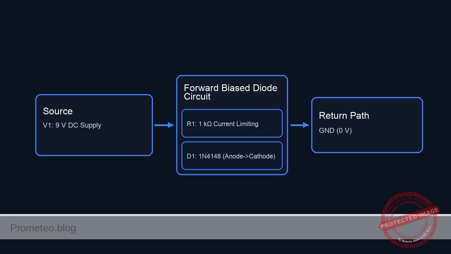
Schematic
[ POWER SOURCE ]               [ CIRCUIT PROCESSING ]                [ RETURN PATH ]

[ V1: 9 V DC Supply ] --(+9 V)--> [ R1: 1 kΩ Resistor ] --(Node N1)--> [ D1: 1N4148 Diode ] --(0 V)--> [ GND ]
                                (Current Limiting)    (Measurement)    (Anode -> Cathode)
                                                                        (Forward Biased)
Measurements and tests
To validate the diode behavior, perform the following measurements using the multimeter.
1. Forward Bias Test (Anode to Positive)
* Voltage Measurement (VD): Set the multimeter to DC Volts. Place the red probe on the Anode (Node N1) and the black probe on the Cathode (Node 0).
* Result: You should read approximately 0.6 V to 0.7 V.
* Current Measurement (ID): Set the multimeter to DC mA. Break the circuit between R1 and D1, and insert the multimeter in series.
* Result: Using Ohm’s Law (I = (Vsource – VD) / R1), the current should be approximately 8.3 mA.
2. Reverse Bias Test (Cathode to Positive)
* Re-wiring: Disconnect D1, flip it 180 degrees, and reconnect it. Now the Cathode (stripe) connects to N1 and the Anode connects to 0.
* Voltage Measurement (VD): Measure across the diode again.
* Result: You should read a value very close to the source voltage (9 V), indicating the diode is acting as an open switch.
* Current Measurement (ID): Measure the current in the loop.
* Result: The reading should be 0 mA (or negligible leakage current in the nano-amp range).
SPICE netlist and simulation
Reference SPICE Netlist (ngspice) — excerptFull SPICE netlist (ngspice)
* Practical case: Forward and Reverse Diode Biasing
* Based on Wiring Guide: Forward Bias Configuration

* --- Power Supply ---
* V1: 9 V DC supply connected between VCC and GND (Node 0)
V1 VCC 0 DC 9

* --- Components ---
* R1: 1 kΩ resistor between VCC and Node N1
R1 VCC N1 1k

* D1: 1N4148 Diode
* Anode connected to N1, Cathode connected to GND (0)
D1 N1 0 D1N4148

* --- Models ---
* Standard 1N4148 Model
.model D1N4148 D (IS=2.682n N=1.836 RS=0.5664 BV=100 IBV=100p CJO=4p TT=11.54n)

* --- Analysis Directives ---
* ... (truncated in public view) ...
Copy this content into a .cir file and run with ngspice.
* Practical case: Forward and Reverse Diode Biasing
* Based on Wiring Guide: Forward Bias Configuration

* --- Power Supply ---
* V1: 9 V DC supply connected between VCC and GND (Node 0)
V1 VCC 0 DC 9

* --- Components ---
* R1: 1 kΩ resistor between VCC and Node N1
R1 VCC N1 1k

* D1: 1N4148 Diode
* Anode connected to N1, Cathode connected to GND (0)
D1 N1 0 D1N4148

* --- Models ---
* Standard 1N4148 Model
.model D1N4148 D (IS=2.682n N=1.836 RS=0.5664 BV=100 IBV=100p CJO=4p TT=11.54n)

* --- Analysis Directives ---
* Operating Point analysis to see DC bias values
.op

* Transient analysis to log data (1ms duration)
.tran 10u 1m

* --- Output Directives ---
* Print supply voltage and diode forward voltage
.print tran V(VCC) V(N1)

.end
Simulation Results (Transient Analysis)

Show raw data table (108 rows)
Index   time            v(vcc)          v(n1)
0	0.000000e+00	9.000000e+00	7.143329e-01
1	1.000000e-07	9.000000e+00	7.143290e-01
2	2.000000e-07	9.000000e+00	7.143286e-01
3	4.000000e-07	9.000000e+00	7.143286e-01
4	8.000000e-07	9.000000e+00	7.143286e-01
5	1.600000e-06	9.000000e+00	7.143286e-01
6	3.200000e-06	9.000000e+00	7.143286e-01
7	6.400000e-06	9.000000e+00	7.143286e-01
8	1.280000e-05	9.000000e+00	7.143286e-01
9	2.280000e-05	9.000000e+00	7.143286e-01
10	3.280000e-05	9.000000e+00	7.143286e-01
11	4.280000e-05	9.000000e+00	7.143286e-01
12	5.280000e-05	9.000000e+00	7.143286e-01
13	6.280000e-05	9.000000e+00	7.143286e-01
14	7.280000e-05	9.000000e+00	7.143286e-01
15	8.280000e-05	9.000000e+00	7.143286e-01
16	9.280000e-05	9.000000e+00	7.143286e-01
17	1.028000e-04	9.000000e+00	7.143286e-01
18	1.128000e-04	9.000000e+00	7.143286e-01
19	1.228000e-04	9.000000e+00	7.143286e-01
20	1.328000e-04	9.000000e+00	7.143286e-01
21	1.428000e-04	9.000000e+00	7.143286e-01
22	1.528000e-04	9.000000e+00	7.143286e-01
23	1.628000e-04	9.000000e+00	7.143286e-01
... (84 more rows) ...
Common mistakes and how to avoid them
- Measuring current in parallel: Never connect the multimeter across the diode while in «Current/Amps» mode. This creates a short circuit and may blow the multimeter’s fuse. Always measure current in series.
- Omitting the resistor: Connecting a diode directly to a voltage source (above 0.7 V) without a resistor will cause unlimited current flow, instantly destroying the diode (and potentially the power supply).
- Misidentifying terminals: The stripe on the diode body indicates the Cathode. In forward bias, the Cathode must point toward the lower potential (GND).
Troubleshooting
- 0 V measured across D1 in Forward Bias: The diode might be shorted internally or the power supply is off. Check V1 voltage first.
- 0 mA in Forward Bias: The circuit is open. Check if the breadboard connections are loose or if the resistor value is too high (e.g., 1 MΩ instead of 1 kΩ).
- 9 V across R1 in Reverse Bias: The diode is conducting when it should not. Ensure D1 is actually reversed (stripe facing positive voltage) or check if D1 is damaged (shorted).
- Diode gets hot: The current is too high. Ensure R1 is at least 330 Ω for a 9 V supply.
Possible improvements and extensions
- Visual Indicator: Replace the standard silicon diode (D1) with an LED. The light will visually confirm when current is flowing (Forward Bias) and turn off when blocked (Reverse Bias).
- I-V Curve Tracing: Use a variable power supply (0 V to 10 V) and record the current at 0.1 V steps to plot the characteristic exponential curve of the diode.
More Practical Cases on Prometeo.blog
Find this product and/or books on this topic on Amazon
As an Amazon Associate, I earn from qualifying purchases. If you buy through this link, you help keep this project running.
Quick Quiz

Telecommunications Electronics Engineer and Computer Engineer (official degrees in Spain).

