Introduction
Have you ever encountered a sudden flicker of lights when you plug in an appliance? That’s a capacitor at work, smoothing out voltage fluctuations. Understanding capacitors can help you appreciate the role they play in everyday electronics. Capacitors are ubiquitous in all electronic devices, from simple circuits to complex machinery, and their importance cannot be overstated. By the end of this tutorial, you will gain a comprehensive understanding of capacitors, including their operation, applications, and how to effectively utilize them in your own projects.
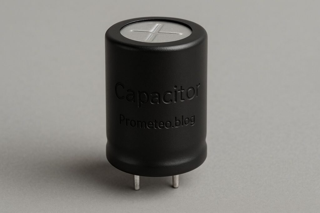
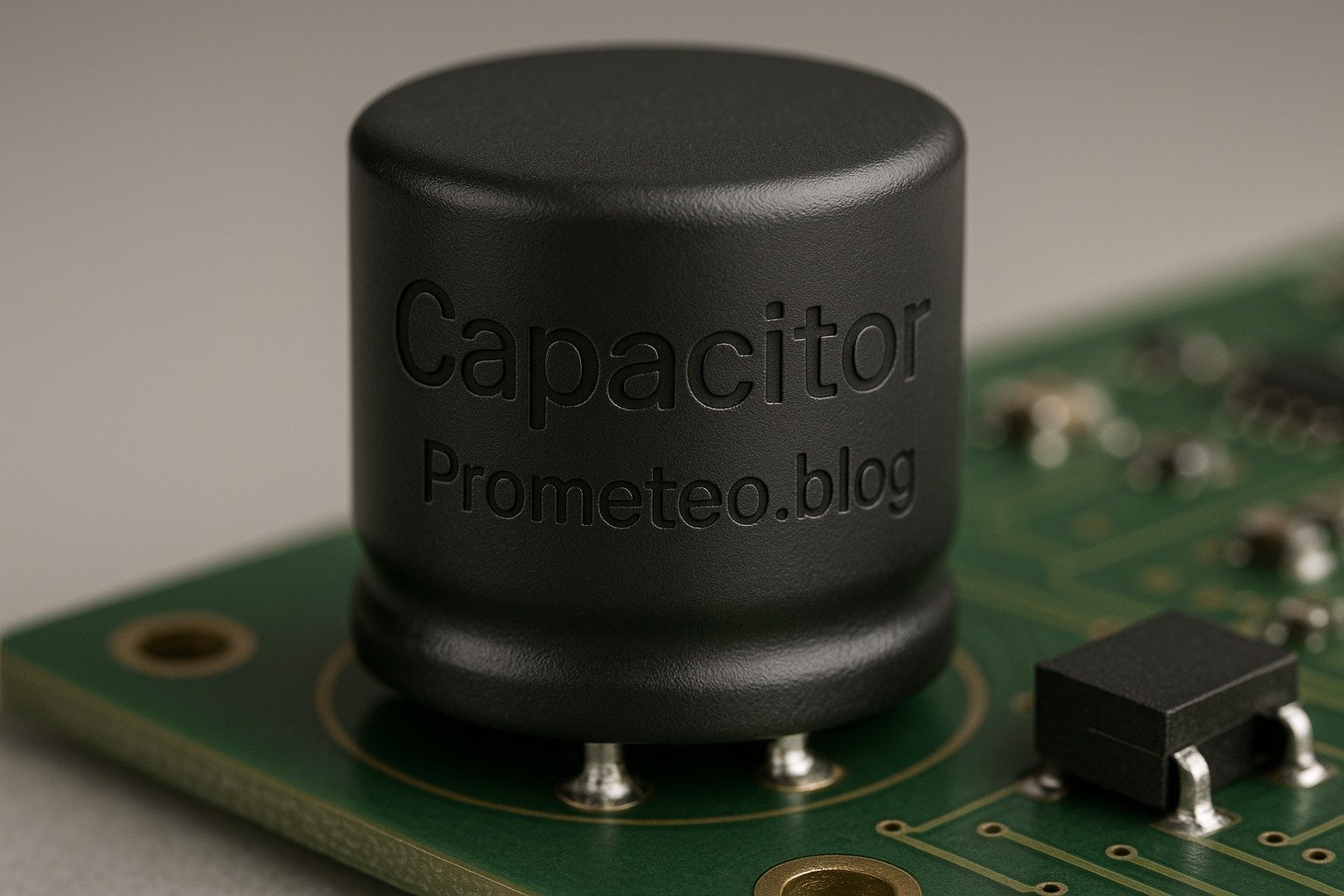
Capacitors are passive electronic components that store electrical energy in an electric field. They are essential for maintaining stable voltage levels, filtering signals, and timing applications. By learning how capacitors function and where they are used, you’ll be better equipped to design and troubleshoot electronic circuits. Whether you’re a hobbyist, student, or professional engineer, this knowledge will enhance your understanding of electronics and empower you to create more effective and reliable circuits.
What it’s used for and how it works
Capacitors are fundamental components in the world of electronics, widely used for various applications. They store and release electrical energy, acting as temporary batteries to stabilize voltage and power supply in circuits. Let’s dive deeper into how they work and where they are typically used.
How Capacitors Store Energy
Capacitors consist of two conductive plates separated by an insulating material called a dielectric. When a voltage is applied across the plates, an electric field forms, allowing the capacitor to store energy. The stored energy can be released when needed, making capacitors essential in smoothing out voltage fluctuations in circuits.
The energy (E) stored in a capacitor can be calculated using the formula:
E = 1 / 2 C V^2
Where:
– E is the energy in joules (J),
– C is the capacitance in farads (F),
– V is the voltage in volts (V).
This equation illustrates that the energy stored in a capacitor increases with both the capacitance and the square of the voltage applied. Therefore, a capacitor with a higher capacitance or a higher voltage will store significantly more energy.
Uses of Capacitors
Capacitors have a broad range of applications, including:
-
Power Supply Smoothing: Capacitors are often used in power supply circuits to smooth out the output voltage. After rectification, the capacitor charges and discharges, minimizing voltage ripple. This is especially critical in power supplies for computers and audio equipment, where stable voltage is necessary for optimal performance.
-
Signal Coupling and Decoupling: In audio and RF circuits, capacitors allow AC signals to pass while blocking DC components. They help maintain signal integrity by decoupling different sections of a circuit. For instance, in audio amplifiers, capacitors can couple audio signals while preventing DC bias from affecting the output.
-
Timing Applications: Capacitors can be used in timing circuits alongside resistors to create delays or oscillations. This is useful in applications like blinking LED circuits, where the timing of the LED’s on-and-off cycle is controlled by the charging and discharging of the capacitor.
-
Energy Storage: In applications like flash photography, capacitors temporarily store energy and release it quickly when needed, providing a burst of power. This allows photographers to capture high-speed action shots with a quick flash.
-
Filtering: Capacitors are used in filters to separate different frequency components of signals. This is crucial in audio processing and communication systems, where unwanted frequencies must be removed to ensure clear sound transmission.
The Physics Behind Capacitors
The amount of charge a capacitor can store is determined by its capacitance, measured in farads (F). The relationship between charge (Q), voltage (V), and capacitance (C) is given by the formula:
Q = C × V
This equation shows that the charge stored in a capacitor increases with both the voltage applied and the capacitance of the capacitor. Therefore, a larger capacitor (higher capacitance) can store more charge at the same voltage, making it more effective for energy storage applications.
Types of Capacitors
There are several types of capacitors, each with specific characteristics:
-
Ceramic Capacitors: Commonly used in high-frequency applications due to their low equivalent series resistance (ESR). They are non-polarized and can handle high voltages, making them ideal for decoupling and filtering applications.
-
Electrolytic Capacitors: Polarized capacitors that provide high capacitance values, suitable for power supply filtering. They are often used in applications where large capacitance is required, such as in power supplies and audio amplifiers.
-
Film Capacitors: Known for stability and low loss, making them ideal for timing applications. They have a longer lifespan and are less prone to failure compared to electrolytic capacitors.
-
Tantalum Capacitors: Similar to electrolytic but offer higher capacitance in a smaller package, often used in compact devices. They are stable and reliable but can be more expensive.
-
Supercapacitors: These can store much more energy than traditional capacitors and are used in applications requiring rapid charging and discharging. Supercapacitors are often found in energy storage systems and hybrid vehicles.
Factors Affecting Performance
The performance of a capacitor is influenced by various factors, including:
-
Capacitance Value: The higher the capacitance, the more charge the capacitor can store. Selecting the right capacitance value is crucial for ensuring the capacitor meets the requirements of your circuit.
-
Voltage Rating: Always ensure that the voltage applied does not exceed the rated voltage to prevent failure. Exceeding the voltage rating can lead to breakdown of the dielectric material and catastrophic failure of the capacitor.
-
Temperature Coefficient: Capacitors can change their capacitance value with temperature variations, which is critical in precision applications. Understanding the temperature coefficient of a capacitor is important for applications that require stable performance over a range of temperatures.
Applications in Everyday Life
Capacitors are found in almost all electronic devices, from smartphones to microwaves. They help manage power supply stability, enhance audio quality, and even play a role in energy-efficient designs. For example, in a smartphone, capacitors are used to smooth the power supply to the processor, ensuring that it operates reliably without voltage fluctuations. In audio systems, capacitors filter out unwanted noise, allowing for clear sound reproduction. Understanding capacitors equips you with the knowledge to troubleshoot and innovate in electronic projects, making them an essential component of modern technology.
Key parameters
| Parameter | Typical | Range | Unit | Note |
|---|---|---|---|---|
| Capacitance | 10 µF | 1 pF – 10 F | F | Main specification |
| Voltage Rating | 25 V | 6.3 V – 1000 V | V | Maximum voltage limit |
| Equivalent Series Resistance (ESR) | 0.1 Ω | 0.01 Ω – 100 Ω | Ω | Affects performance at high frequencies |
| Temperature Coefficient | ±10% | ±1% – ±20% | — | Variation with temperature |
| Leakage Current | 1 µA | 0.01 µA – 10 mA | A | Current loss over time |
Understanding these key parameters will help you select the right capacitor for your specific needs. For example, if you are designing a power supply circuit, you may prioritize a capacitor with a high capacitance and a suitable voltage rating to ensure stability and reliability. Conversely, in high-frequency applications, you may focus on minimizing ESR to enhance performance.
Hands-on practical project: Capacitor-based LED Blinking Circuit
Goal: Control an LED to blink at a steady rate using a capacitor, verifying that the LED blinks at a frequency of 1 Hz.
Estimated time: 45 minutes.
Materials
- 1 × 220 Ω resistor — Current limiting for LED.
- 1 × 10 µF capacitor — Stores charge to control blinking.
- 1 × LED — Visual output for the circuit.
- 1 × NPN transistor — Acts as a switch for the LED.
- 1 × 9 V battery — Power source for the circuit.
- 1 × breadboard — For easy circuit assembly.
- 2 × jumper wires (red and black) — For making connections.
- 1 × 1 kΩ resistor — Base resistor for the transistor.
Step-by-step build
- Place the components on the breadboard
Start by placing the NPN transistor on the breadboard. Connect the collector pin of the transistor to the anode of the LED. The LED’s cathode should connect to the ground rail of the breadboard. This setup allows the transistor to control the LED. -
Check: Ensure the LED’s anode is correctly connected to the collector.
-
Connect the resistor and capacitor
Connect the 220 Ω resistor from the LED’s anode to the positive rail. Next, attach the capacitor across the collector and emitter of the transistor, ensuring the positive side connects to the collector. This configuration allows the capacitor to charge and discharge, controlling the blinking rate. -
Check: Confirm the capacitor’s positive lead is in the correct orientation.
-
Add the base resistor
Connect the base of the transistor to one end of the 1 kΩ resistor, and connect the other end to the positive rail. This resistor limits the current flowing into the base of the transistor, protecting it from damage. The base controls the transistor’s switching behavior. -
Check: Double-check that the base resistor is correctly connected.
-
Connect the power supply
Finally, connect the 9 V battery’s positive terminal to the positive rail of the breadboard and the negative terminal to the ground rail. Ensure all connections are secure. This power will energize the circuit, allowing the capacitor to function correctly. - Check: Verify that the battery connections are secure and correct.
Testing and validation
- Power up the circuit
Once everything is connected, switch on the power by connecting the battery. Observe the LED. It should start blinking at a steady rate. If it does not blink, recheck all connections, especially the capacitor and transistor orientation. -
Check: Confirm the LED blinks at approximately 1 Hz.
-
Adjust the blinking rate
To modify the blinking speed, you can experiment with different capacitance values or resistor values. Replacing the 10 µF capacitor with a higher value will slow the blink rate, while a lower value will speed it up. Test and adjust accordingly. - Check: Ensure the LED still blinks steadily after adjustments.
Extend the project
- Use a variable resistor to control the blink rate.
- Add more LEDs in parallel to create a blinking pattern.
- Implement a different type of capacitor to see how it affects performance.
- Integrate a microcontroller to add more complex blinking patterns.
Safety
- Always double-check the voltage rating of the components before use.
- Ensure that the power supply is disconnected while assembling the circuit.
- Avoid touching live wires when the circuit is powered.
- Use resistors with appropriate ratings to prevent overheating.
- Work in a dry environment to prevent any short circuits.
Common mistakes and how to avoid them
-
Incorrect Capacitor Polarity: Ensure that polarized capacitors (like electrolytics) are installed in the correct orientation. Check the markings before soldering. If a polarized capacitor is connected backward, it can fail spectacularly, sometimes exploding.
-
Overloading the Capacitor: Do not exceed the voltage rating; otherwise, the capacitor may fail. Always check the specifications. If unsure, opt for a capacitor with a higher voltage rating than required.
-
Loose Connections: In breadboard setups, ensure all connections are secure. Loose connections can lead to intermittent issues. A good practice is to gently tug on wires to confirm they are firmly seated.
-
Wrong Component Values: Double-check resistor and capacitor values before assembly. Using incorrect values may lead to unexpected results. It’s advisable to use a multimeter to verify component values if in doubt.
-
Ignoring Temperature Effects: Be mindful that capacitance can change with temperature. For critical applications, consider using temperature-compensated capacitors. Always consult the datasheet for the capacitor to understand its behavior under varying conditions.
Conclusion
Understanding capacitors is crucial for anyone working with electronics. They play pivotal roles in smoothing power supplies, filtering signals, and timing applications. By experimenting with hands-on projects, you can appreciate their functionality even more. So, gather your materials, build something exciting, and dive deeper into the world of capacitors! More information at prometeo.blog
Third-party readings
- Micro:bit Capacitor Experiment / Medición del tiempo de carga
- ¿Qué es un condensador y cómo funciona? – Física y aplicaciones
- Tutorial de electrónica #9 – Condensadores – Parte 1
Find this product and/or books on this topic on Amazon
As an Amazon Associate, I earn from qualifying purchases. If you buy through this link, you help keep this project running.
Quick Quiz

Telecommunications Electronics Engineer and Computer Engineer (official degrees in Spain).