Introduction
Have you ever wondered how your smartphone efficiently charges without overheating? The answer lies in a small but crucial component: the diode. This unassuming device plays a pivotal role in the world of electronics, ensuring that currents flow in the right direction and that devices operate safely and efficiently. In this tutorial, we will explore the various uses and functionalities of diodes, shedding light on their importance in modern electronic circuits. By the end, you’ll have a comprehensive understanding of diodes, their working principles, and how you can utilize them in practical applications.
What it’s used for and how it works
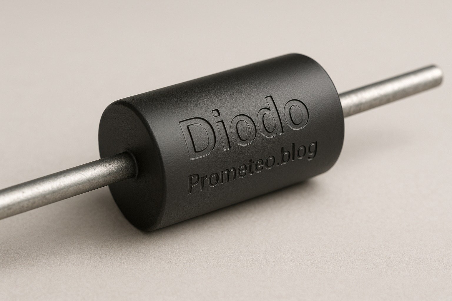
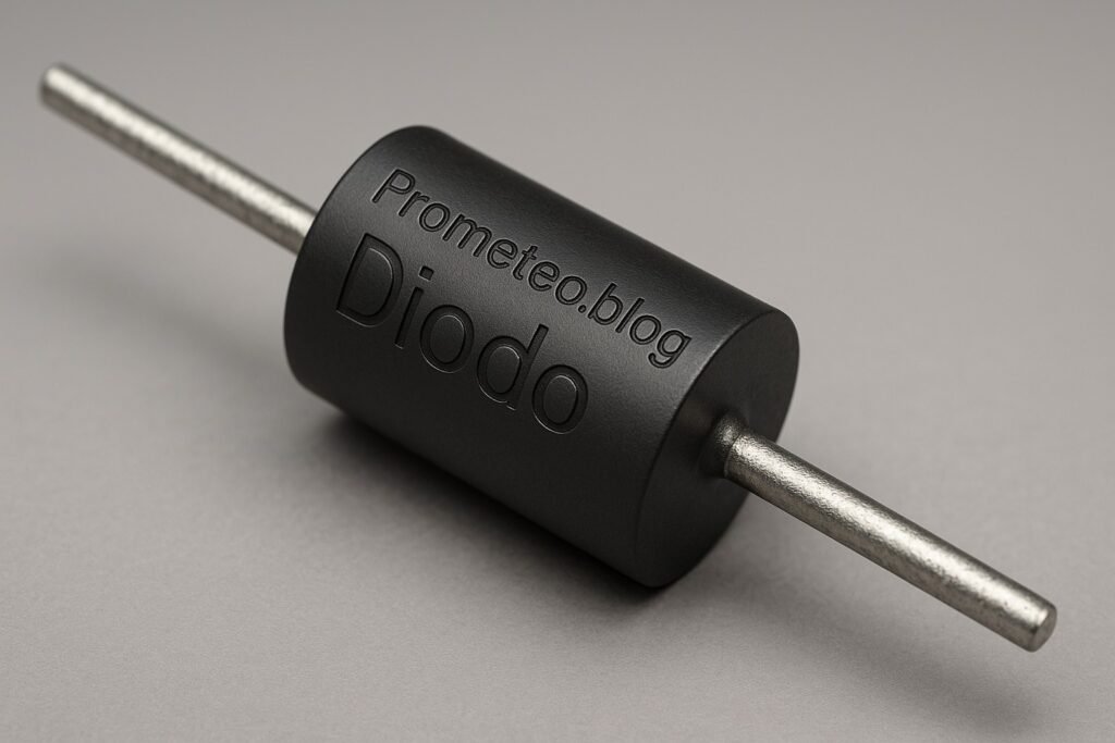
Diodes are essential components in electronics, serving various critical functions. At their core, diodes are semiconductor devices that allow current to flow in one direction while blocking it in the opposite direction. This property makes them ideal for rectification, which converts alternating current (AC) to direct current (DC). To understand how a diode works, let’s delve into its construction and operation.
Construction of a Diode
A typical diode consists of two layers of semiconductor material: p-type and n-type. The p-type semiconductor contains an abundance of holes (positive charge carriers), while the n-type semiconductor has an excess of electrons (negative charge carriers). When these two materials are joined together, a p-n junction is formed. This junction creates an electric field at the interface, which is pivotal to the diode’s behavior.
The p-n junction is the heart of the diode. When a forward voltage is applied, it allows current to flow, while a reverse voltage creates a barrier that prevents current from flowing. This unique characteristic is what makes diodes so useful in electronic circuits.
How Diodes Work
When a forward voltage is applied across the diode (positive to the p-type and negative to the n-type), the electrons and holes move towards the junction, allowing current to flow. This is known as forward biasing. In this state, the diode conducts electricity, and the voltage drop across it is typically around 0.7 volts for silicon diodes. Conversely, if the voltage is reversed, the junction becomes depleted of charge carriers, and the current is effectively blocked, which is referred to as reverse biasing. In this state, the diode acts as an insulator, preventing current from flowing.
Applications of Diodes
Diodes are employed in various circuits and applications, showcasing their versatility and importance in electronics. Here are some common applications:
-
Rectifiers: As mentioned, diodes convert AC to DC. This function is vital in power supplies for electronic devices. For example, in a typical power supply circuit, diodes are used in a bridge rectifier configuration to convert the AC voltage from the mains to a usable DC voltage.
-
Clippers and Clampers: Diodes can be used to clip or limit voltage levels in a circuit, preventing damage to sensitive components. For instance, in audio circuits, diodes can be employed to limit the amplitude of audio signals, protecting amplifiers from distortion caused by excessively high voltages.
-
Voltage Regulation: Zener diodes serve as voltage regulators, maintaining a stable output voltage regardless of variations in input voltage. This is crucial in circuits where a constant voltage is necessary, such as in power supply circuits for microcontrollers.
-
Signal Demodulation: In communication systems, diodes can extract information from modulated signals. For example, in AM radio receivers, diodes are used to demodulate the audio signal from the carrier wave, allowing us to hear the transmitted audio.
-
LEDs: Light Emitting Diodes emit light when current flows through them, making them widely used in displays and indicators. LEDs are known for their energy efficiency and long lifespan, making them the preferred choice for lighting applications.
-
Protection Circuits: Diodes can protect circuits from voltage spikes, such as in flyback diodes used in inductive loads. For instance, in relay circuits, a flyback diode prevents back electromotive force (EMF) from damaging the circuit when the relay is turned off.
-
Solar Cells: Diodes are also used in solar power systems to prevent reverse current flow from the battery back to the solar panels. This ensures that the energy harvested from sunlight is stored efficiently.
Diodes are classified into various types based on their characteristics and applications:
– Standard Diodes: General-purpose diodes used in rectification.
– Zener Diodes: Specialized diodes that allow current to flow in the reverse direction when a specific voltage is reached, providing voltage regulation.
– Schottky Diodes: Known for their fast switching speeds and low forward voltage drop, making them ideal for high-frequency applications such as in switching power supplies.
– Light Emitting Diodes (LEDs): As previously mentioned, these produce light and are used in displays and indicators.
Understanding how diodes function and their applications in different circuits is crucial for anyone delving into electronics. Their ability to control current direction and voltage levels makes them indispensable components in modern electronic devices.
Key parameters
| Parameter | Typical | Range | Unit | Note |
|---|---|---|---|---|
| Forward Current (If) | 1 | 0.1 – 3 | A | Maximum current in forward bias |
| Reverse Voltage (Vr) | 50 | 5 – 1000 | V | Maximum voltage in reverse bias |
| Forward Voltage (Vf) | 0.7 | 0.2 – 1.5 | V | Voltage drop when forward biased |
| Reverse Current (Ir) | 0.1 | 0.01 – 100 | mA | Leakage current in reverse bias |
| Junction Temperature (Tj) | 150 | -55 – 175 | °C | Maximum junction temperature |
| Capacitance (C) | 10 | 1 – 1000 | pF | Junction capacitance at zero bias |
| Recovery Time (trr) | 50 | 10 – 1000 | ns | Time to switch from conducting to non-conducting |
These parameters offer insight into the operational limits and characteristics of diodes, guiding engineers and hobbyists in selecting the right diode for their applications. For instance, the forward current rating indicates how much current the diode can handle without overheating, while the reverse voltage rating shows the maximum voltage the diode can withstand in the reverse direction before breakdown occurs.
Hands-on practical project: Build a Simple Diode Rectifier
Goal: Construct a diode rectifier to convert AC voltage to DC voltage, verifying a stable DC output with a multimeter.
Estimated time: 45 minutes
Materials
- 1 × diode (1N4007) — standard rectifier diode
- 1 × transformer (9 V) — reduces AC voltage
- 1 × capacitor (1000 µF) — smooths out the DC output
- 1 × resistor (220 Ω) — limits current for safety
- 1 × multimeter — measures voltage output
- 2 × jumper wires (red and black) — connect circuit components
- 1 × breadboard — prototype the circuit
Step-by-step build
- Connect the Transformer
Start by connecting the primary winding of the transformer to an AC power source. Ensure you use proper insulation and safety measures. The secondary winding will output a lower AC voltage. -
Check: Transformer is securely connected and powered.
-
Wire the Diode
Connect the secondary side of the transformer to the anode of the diode. Ensure the cathode (marked with a stripe) is oriented towards the output side. This orientation allows current to flow only in one direction. -
Check: Diode is correctly oriented.
-
Add the Capacitor
Connect the cathode of the diode to one terminal of the capacitor. Connect the other terminal of the capacitor to the ground (negative terminal). The capacitor will charge during the positive half-cycle of the AC signal. -
Check: Capacitor is connected to the diode output correctly.
-
Place the Resistor
Connect the resistor in series with the capacitor to limit the current flowing into the load. This will help protect both the diode and the capacitor from excessive current. -
Check: Resistor is properly connected.
-
Connect the Output
Now, connect a multimeter to the output (across the capacitor) to measure the DC voltage. Make sure to set the multimeter to the appropriate DC voltage range. -
Check: Multimeter is set to measure DC voltage.
-
Power On and Test
Finally, power on the transformer and observe the multimeter reading. You should see a stable DC voltage output. Observe the ripple on the waveform to ensure the capacitor is effectively smoothing out the AC waveform. - Check: Stable DC voltage reading on the multimeter.
Testing and validation
- Measure the Output Voltage
Use the multimeter to measure the voltage across the capacitor. You should observe a DC voltage that is typically around 6-7 V for a 9 V transformer due to the diode voltage drop. -
Check: Voltage reading corresponds to expected values.
-
Observe Ripple
If you have an oscilloscope, connect it to the output to visualize the ripple voltage. Ensure that the ripple voltage is minimal, confirming the capacitor’s effectiveness. - Check: Ripple voltage is within acceptable limits (ideally less than 1 V).
Extend the project
- Experiment with different transformer voltages to see how it affects the output. For example, using a 12 V transformer may yield a higher DC output, but it’s crucial to monitor the diode’s ratings to avoid damage.
- Add more capacitors in parallel to increase filtering capacity. This can help reduce ripple further and provide a more stable voltage output.
- Implement a Zener diode for voltage regulation on the output. This can help maintain a constant voltage level, even if the input voltage fluctuates.
- Use a load (like an LED) to see how the circuit responds under load conditions. This will help you understand how diodes behave when the circuit is not just an open loop.
Safety
- Always ensure the circuit is disconnected from power when assembling. This prevents accidental shocks or short circuits while working on the circuit.
- Use insulated tools to avoid electric shock. Tools with rubber grips can provide additional safety.
- Verify the voltage ratings of components are appropriate for your circuit. Overrating components can lead to failure.
- Keep the workspace dry and free from conductive materials. This minimizes the risk of short circuits or accidental connections.
- Do not exceed the diode’s rated current or voltage. Always refer to the datasheet for specifications.
Common mistakes and how to avoid them
- Incorrect Diode Orientation: Always check the anode and cathode connections before powering on. A reversed diode can lead to circuit failure and potential damage.
- Overloading Components: Ensure that the current and voltage ratings of all components are respected to prevent damage. Using components that are rated too low can lead to overheating and failure.
- Neglecting Safety Precautions: Always work with insulated tools and ensure circuits are powered off during assembly. This is crucial for personal safety.
- Inadequate Filtering: If ripple is too high, consider increasing capacitor value or adding more capacitors. Insufficient filtering can lead to unstable output and potential circuit malfunction.
Conclusion
Diodes are fundamental components in electronics, enabling various applications from rectification to protection. Understanding their operation and parameters is essential for successful circuit design. By building a simple diode rectifier, you gain hands-on experience that solidifies your theoretical knowledge. Don’t hesitate to experiment further with diodes in your projects! More information at prometeo.blog
Third-party readings
- Diodo – MST-tutorial
- Tutorial Diodo: Conceitos e Aplicações Eletrônicas Básicas
- Diodo Túnel: Diodo de Micro-Ondas Easki – Blog Raisa
Find this product and/or books on this topic on Amazon
As an Amazon Associate, I earn from qualifying purchases. If you buy through this link, you help keep this project running.
Quick Quiz


