Introduction
In my early days as an engineer, I was fascinated by how light could be converted into electrical signals. One day, while playing around with a simple Fotodiodo, I managed to create a light-sensitive alarm system. This sparked my passion for exploring the world of photodetectors and their incredible applications. Photodetectors, particularly Fotodiodos, have become integral in modern technology, enabling devices to respond to light in innovative ways. Through this tutorial, I aim to share both the theoretical foundations and practical applications of Fotodiodos, ensuring that you gain a comprehensive understanding of their functionality and uses.
As we delve deeper into the workings of Fotodiodos, you will learn about their operational principles, key parameters that define their performance, and how to implement a hands-on project that utilizes these fascinating devices. Whether you are a beginner in electronics or an experienced engineer looking to refresh your knowledge, this tutorial will provide valuable insights into the world of Fotodiodos.
What it’s used for and how it works
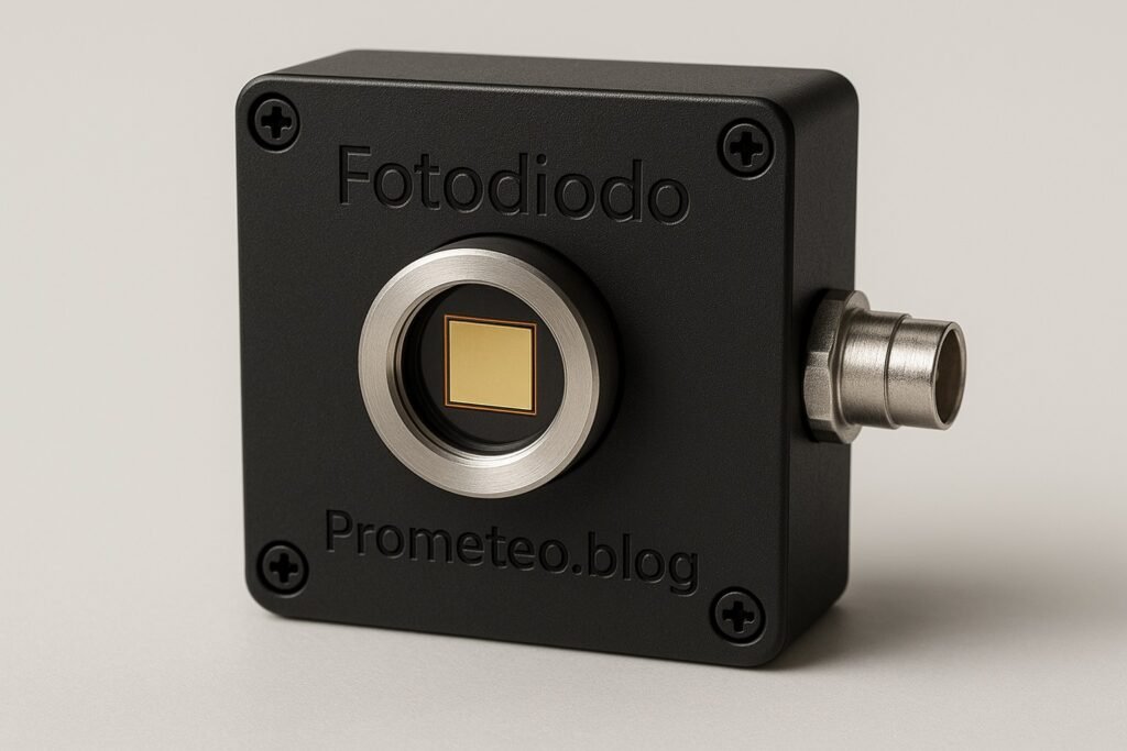
A Fotodiodo, or photodiode, is a semiconductor device that converts light into an electrical current. This process occurs due to the photoelectric effect, where photons incident on the diode generate electron-hole pairs, leading to a flow of current. Fotodiodos are widely used in various applications such as light detection, optical communication, and even in safety systems.
In essence, when light strikes the photodiode, it creates an electric current that is proportional to the intensity of the light. The fundamental principle behind this operation is based on a p-n junction, which is formed by combining p-type and n-type semiconductors. When light is absorbed in the depletion region of this junction, generated carriers can move under an applied voltage, producing a measurable current.
Working Principle
The working principle of a Fotodiodo can be summarized in the following steps:
1. Absorption of Light: When light photons hit the photodiode, they are absorbed by the semiconductor material. This absorption is highly dependent on the wavelength of the incoming light, as different materials have different absorption coefficients.
2. Generation of Charge Carriers: This absorption leads to the creation of electron-hole pairs in the depletion region of the diode. The efficiency of this process is characterized by the photodiode’s responsivity, which indicates how effectively the device converts light into electrical current.
3. Movement of Charge Carriers: The built-in electric field in the depletion region drives these charge carriers towards the respective electrodes, resulting in a flow of current. The direction of this flow is determined by the polarity of the applied voltage across the photodiode.
4. Current Output: The output current is directly proportional to the intensity of the incident light, which can be measured using an external circuit. This linear relationship allows for straightforward applications in light sensing and communication systems.
Types of Fotodiodos
There are mainly two types of Fotodiodos: Photoconductive and Photoelectric. The photoconductive type is operated in reverse bias, providing high-speed response, making it suitable for fiber-optic applications. This configuration allows the photodiode to respond quickly to changes in light intensity, making it ideal for high-frequency applications such as data transmission. Conversely, the photoelectric type is often used in solar cells, where the output current is derived from the generated electron-hole pairs under illumination. This type is typically used in applications where a continuous current output is required, such as in power generation.
Applications
- Optical Communication: Fotodiodos are crucial in converting light signals into electrical signals in fiber-optic communication systems. They play a vital role in high-speed internet and telecommunications, where data is transmitted as light pulses through optical fibers.
- Light Sensing: They are widely used in light sensors for automatic lighting systems, allowing devices to turn on or off based on ambient light levels. For example, streetlights equipped with Fotodiodos can automatically turn on at dusk and off at dawn, conserving energy.
- Medical Equipment: In medical devices, Fotodiodos are used in pulse oximeters to measure blood oxygen levels by detecting light absorption in blood. This non-invasive method has revolutionized patient monitoring in healthcare settings.
- Safety Systems: They can be integrated into safety systems, such as smoke detectors, where they monitor changes in light caused by smoke particles. The presence of smoke alters the light path, triggering an alarm to alert occupants of potential danger.
- Consumer Electronics: Many consumer devices like remote controls utilize Fotodiodos for receiving infrared signals. They enable seamless communication between devices, enhancing user experience in home entertainment systems.
Overall, Fotodiodos play a pivotal role in modern electronics, enabling various technologies that depend on light detection and conversion. Understanding how they function and their applications can lead you to innovate and design effective systems in your projects. The versatility of Fotodiodos makes them a valuable component in both consumer and industrial applications, highlighting their significance in contemporary technology.
Key parameters
| Parameter | Typical | Range | Unit | Note |
|---|---|---|---|---|
| Responsivity | 0.5 | 0.1 – 1.0 | A/W | Sensitivity to light |
| Dark Current | 10 | 1 – 100 | nA | Current in absence of light |
| Capacitance | 10 | 1 – 100 | pF | Junction capacitance |
| Speed | 10 | 1 – 100 | MHz | Frequency response |
| Operating Voltage | 5 | 0 – 30 | V | Reverse bias voltage |
| Wavelength Range | 400 – 1100 | 300 – 1600 | nm | Sensitivity range |
| Temperature Range | -40 to 85 | -55 to 125 | °C | Operating temperature |
The above table summarizes the key parameters that define the performance of a Fotodiodo. These parameters are crucial when selecting a photodiode for a specific application, as they directly influence the device’s efficiency and effectiveness. For instance, a higher responsivity indicates that the photodiode will generate more current for a given light intensity, making it suitable for low-light applications. Similarly, understanding the dark current is essential for applications that require precision, as a high dark current can introduce noise and reduce the accuracy of the measurements.
Hands-on practical project: Light-controlled LED with Photodiode
Goal: Control an LED using a Fotodiodo to indicate light intensity in a room, verifying that the LED turns on at a specific light level of 100 lux.
Estimated time: 45 minutes
Materials
- 1 × Fotodiodo — Light-sensitive device for detection.
- 1 × LED — Indicator light for output.
- 1 × 220 Ω resistor — Current limiting for the LED.
- 1 × 10 kΩ resistor — Pull-up resistor for the circuit.
- 1 × NPN transistor — To control LED based on Fotodiodo output.
- 2 × jumper wires (red and black) — For connections.
- 1 × breadboard — For assembling the circuit.
- 1 × power supply (9 V) — Provides power to the circuit.
Step-by-step build
- Connect the Fotodiodo: Place the Fotodiodo on the breadboard. Connect the anode (positive) to the power supply terminal and the cathode (negative) to one end of the 10 kΩ resistor. The other end of this resistor will connect to the base of the NPN transistor. This configuration allows the Fotodiodo to generate a voltage that can control the transistor.
-
Check: Ensure the Fotodiodo is correctly oriented with the anode connected to the power supply. A common mistake is reversing the anode and cathode, which will prevent the circuit from functioning.
-
Wire the NPN transistor: Insert the NPN transistor on the breadboard. Connect the emitter to the ground. Connect the collector to the LED’s cathode. The anode of the LED will connect to the positive terminal through the 220 Ω resistor. This arrangement allows the transistor to control the LED based on the Fotodiodo’s output.
-
Check: Verify the correct pin configuration of the transistor (emitter, base, collector). Each transistor has a specific pin arrangement, and mixing them up can lead to circuit failure.
-
Connect the LED: Place the LED on the breadboard. Connect the anode (longer lead) to the 9 V power supply through the 220 Ω resistor. The cathode (shorter lead) should be connected to the collector of the NPN transistor. This setup ensures that when the transistor is activated, the LED will light up.
-
Check: Ensure the LED is connected correctly, observing the polarity. LEDs are polarized components, and incorrect connections will prevent them from lighting up.
-
Power the circuit: Finally, connect the power supply to the circuit. When light falls on the Fotodiodo, it generates a current that turns on the NPN transistor, allowing current to flow through the LED. Adjust the ambient light level to observe the LED’s response.
- Check: Confirm that the LED turns on and off as the light intensity changes. If it does not respond as expected, review all connections and component orientations.
Testing and validation
- Measure Light Levels: Use a light meter to measure the illumination level in the room. Adjust the light intensity to see if the LED responds accurately at the target of 100 lux. If the LED does not turn on, check the connections and the resistance values.
- Confirm Operation: Ensure that the LED indeed turns on when the light intensity exceeds 100 lux and turns off when it drops below that threshold. This confirms that your circuit is functioning as intended.
- Check: Verify that the LED operates correctly based on light levels. If it does not, consider adjusting the sensitivity by changing the resistor values or the positioning of the Fotodiodo.
Extend the project
- Add a potentiometer to adjust the sensitivity of the Fotodiodo. This will allow you to fine-tune the light level at which the LED turns on or off.
- Integrate a microcontroller for more complex light processing. This could enable features like programmable thresholds or data logging.
- Use multiple LEDs to indicate different light intensity ranges. For example, you could have green for low light, yellow for moderate light, and red for high light levels.
- Implement a buzzer to sound an alarm when a certain light threshold is reached. This could be useful for alerting in safety applications or for creating an interactive lighting system.
Safety
- Always connect the circuit with the power supply turned off. This practice minimizes the risk of short circuits or component damage.
- Use resistors to prevent damage from excessive current. Resistors are essential for controlling current flow and protecting sensitive components like LEDs and transistors.
- Ensure proper orientation of the Fotodiodo and LED to avoid reverse polarity. Incorrect connections can lead to component failure or malfunction.
- Avoid looking directly at bright light sources while testing. Protect your eyes from potential damage when working with intense light sources.
- Be cautious of short circuits when handling wires and components. Double-check your connections to ensure that there are no unintended paths for current to flow.
Common mistakes and how to avoid them
- Incorrect polarity: Double-check the orientation of the Fotodiodo and LED. A common error is connecting these components backward, which can prevent them from working.
- Wrong resistor values: Ensure you are using the correct resistor values for current limiting. Using a resistor that is too high may prevent the LED from lighting up, while one that is too low can damage the LED.
- Loose connections: Make sure all connections are secure on the breadboard. Loose connections can lead to intermittent functionality, making troubleshooting difficult.
- Ignoring light levels: Use a light meter to validate ambient light levels for proper functionality. This will help you ensure that the circuit operates as intended under varying light conditions.
- Powering on without checks: Always ensure the circuit is set up correctly before applying power. This precaution can save components from damage and prevent frustration during testing.
Conclusion
In summary, you have learned about Fotodiodos and their important role in various applications, as well as how to build a simple yet effective light-controlled LED circuit. By experimenting with this project, you can deepen your understanding of light sensing and its potential applications. I encourage you to explore further and even extend this project to create more complex systems. The knowledge gained from this exploration can be applied to numerous fields, including telecommunications, safety systems, and consumer electronics. Embrace the world of electronics, and let your creativity guide you in developing innovative solutions. More information at prometeo.blog
Third-party readings
Find this product and/or books on this topic on Amazon
As an Amazon Associate, I earn from qualifying purchases. If you buy through this link, you help keep this project running.
Quick Quiz

Telecommunications Electronics Engineer and Computer Engineer (official degrees in Spain).