Introduction
Many of us have encountered light-sensitive devices without realizing their sophistication. I remember a time when I made a simple light-activated switch for my desk lamp using a photoresistor, or as it is known in English, a light-dependent resistor (LDR). This experience opened my eyes to the fascinating world of electronics. The ability to harness light as a control mechanism is not only intriguing but also serves as the foundation for various automated systems that enhance our daily lives. In this tutorial, we will explore the intricacies of photoresistors, their applications, and how you can use them in practical projects.
What it’s used for and how it works
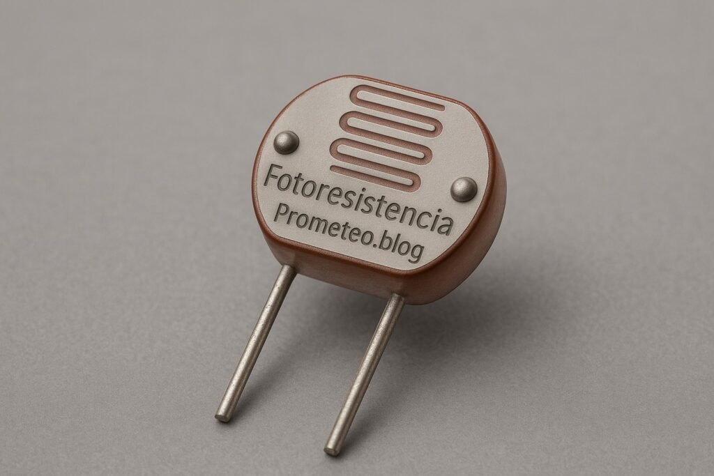
A photoresistor, or LDR, is a type of resistor whose resistance decreases with increasing incident light intensity. This characteristic makes them incredibly useful in a variety of applications, ranging from simple hobbies to complex engineering projects. In essence, photoresistors are made from semiconductor materials that exhibit photoconductivity, meaning they change their electrical conductivity based on the amount of light they receive. This property allows them to be utilized in various circuits and systems that require light detection.
How it works
When light falls on a photoresistor, the photons are absorbed by the semiconductor material, which causes electrons to be excited from the valence band to the conduction band. This process effectively reduces the resistance of the material, allowing more current to flow through it. Conversely, in darkness, the resistance of the LDR increases significantly, limiting the current. Typically, photoresistors are used in circuits where light detection is necessary, such as in light meters, automatic streetlights, and even in alarm systems.
The working principle can be further understood by considering the energy band theory of semiconductors. In the absence of light, the electrons in the semiconductor material are bound in the valence band, and the material exhibits high resistance. When light photons strike the material, they impart energy to the electrons, allowing them to jump into the conduction band. As more electrons become free to move, the conductivity of the material increases, resulting in a decrease in resistance.
Practical uses
-
Automatic lighting systems: Photoresistors can detect ambient light levels and automatically turn lights on or off. For instance, streetlights can use LDRs to turn on at dusk and off at dawn. This automation not only saves energy but also enhances safety on the roads.
-
Light-sensitive alarms: An LDR can be employed in security systems to detect unauthorized movement based on changes in light intensity. For example, if a door is opened and light enters a previously dark room, the LDR can trigger an alarm.
-
Photography equipment: Light meters use photoresistors to measure light exposure, assisting photographers in achieving the correct exposure settings. By providing real-time feedback on light conditions, photographers can make informed adjustments to their camera settings.
-
Solar trackers: In solar panel systems, photoresistors can help adjust the angle of the panels to maximize sunlight exposure throughout the day. This ensures that solar panels capture the maximum amount of energy, improving overall efficiency.
-
Display screens: LDRs are utilized in screens to adjust brightness automatically based on ambient light conditions, enhancing user experience and saving energy. For instance, smartphones often use LDRs to dim the display in low-light environments, reducing eye strain.
Advantages and disadvantages
One of the main advantages of photoresistors is their simplicity and ease of use. They don’t require any power to operate, making them cost-effective. This characteristic is particularly beneficial for battery-operated devices, where minimizing power consumption is crucial. Additionally, LDRs are widely available and come in various sizes and specifications, making them accessible for hobbyists and professionals alike.
However, they also have some downsides. For example, their response time is relatively slow compared to other light sensors like photodiodes. This means that in rapidly changing light conditions, photoresistors may not provide timely readings. Additionally, they can be affected by temperature changes, which might lead to inaccuracies in light detection. For instance, extreme temperatures can alter the resistance characteristics of the LDR, affecting its performance.
Practical considerations
When using photoresistors in your projects, it’s important to consider factors such as ambient temperature and humidity, as these can affect their performance. Moreover, the output from a photoresistor is an analog signal, meaning you’ll often need additional components like operational amplifiers or microcontrollers to interpret the readings accurately. Therefore, understanding how to integrate LDRs into your circuits is crucial for obtaining reliable results.
Additionally, the placement of the photoresistor in your project can significantly impact its effectiveness. For example, if you are using it in an outdoor application, ensure that it is shielded from direct rain or extreme weather conditions to maintain its longevity. Furthermore, consider using a housing or enclosure that allows light to enter while protecting the sensor from environmental factors.
Key parameters
| Parameter | Typical | Range | Unit | Note |
|---|---|---|---|---|
| Resistance (light) | 10 kΩ | 1 kΩ – 50 kΩ | Ω | Resistance under bright light |
| Resistance (dark) | 1 MΩ | 100 kΩ – 10 MΩ | Ω | Resistance in darkness |
| Spectral response | 400 nm | 350 nm – 700 nm | nm | Sensitivity to light wavelength |
| Maximum power | 100 mW | 0.1 mW – 200 mW | mW | Power dissipation limit |
| Operating temperature | 25 °C | -40 °C – 85 °C | °C | Standard operating range |
Understanding these parameters is essential for selecting the right photoresistor for your specific application. For example, if you are designing a light-sensitive alarm system, you may want to choose an LDR with a lower resistance in bright light to ensure a quick response. On the other hand, for applications requiring high sensitivity in low light, a photoresistor with a higher dark resistance may be more suitable.
Hands-on practical project: Automatic garden light control
Goal: Use a photoresistor to control an LED garden light based on ambient light conditions, verifying that the LED turns on when light levels drop below a defined threshold.
Estimated time: 45 minutes
Materials
- 1 × photoresistor — Light-sensitive component for detection.
- 1 × NPN transistor (e.g., 2N3904) — To control the LED based on LDR output.
- 1 × LED — The light source to be controlled.
- 1 × 220 Ω resistor — Current limiting resistor for the LED.
- 1 × 10 kΩ resistor — Used with the photoresistor for voltage divider.
- 1 × 9 V battery — Power source for the circuit.
- 2 × jumper wires (red and black) — For connections in the circuit.
- 1 × breadboard — Base for assembling the circuit components.
Step-by-step build
- Connect the photoresistor: Place the photoresistor on the breadboard. Connect one terminal to the positive rail (+) of the breadboard and the other terminal to one end of the 10 kΩ resistor. Attach the other end of the 10 kΩ resistor to the ground rail (-). This creates a voltage divider circuit.
-
Check: Ensure that the photoresistor is connected correctly for proper voltage division. The voltage at the junction between the photoresistor and the resistor will vary based on light levels.
-
Wire the transistor: Insert the NPN transistor on the breadboard. Connect the base of the transistor to the junction between the photoresistor and the 10 kΩ resistor. This will allow the voltage at this point to control the transistor’s state.
-
Check: Verify that the base is correctly connected to the voltage divider output. This connection is crucial for the transistor to switch on and off based on light levels.
-
Connect the LED: Attach the LED to the collector of the NPN transistor. Connect the anode (long leg) of the LED to the collector and the cathode (short leg) to the negative rail of the breadboard. Add the 220 Ω resistor in series with the LED to limit current through it.
-
Check: Ensure the LED is oriented correctly to avoid damage. An incorrectly oriented LED will not light up and could be damaged if powered.
-
Power the circuit: Connect the emitter of the transistor to the ground rail. Then, connect the positive terminal of the 9 V battery to the positive rail of the breadboard and the negative terminal to the ground rail. This will power the entire circuit.
-
Check: Make sure the battery connections are secure and polarity is correct. A reverse connection may damage the components.
-
Testing the setup: With the circuit powered, cover the photoresistor with your hand or a dark object. Observe if the LED turns on. Adjust the environmental light to see if the LED turns off when there’s sufficient light.
- Check: Confirm the LED operates correctly in response to light changes. The LED should respond promptly to the light conditions.
Testing and validation
- Validate functionality: Test the circuit by exposing the photoresistor to different light levels. The LED should turn on in low light and turn off in bright light. Ensure it responds quickly and accurately to changes.
- Check: Verify that the LED performs as expected under varying light conditions. If the LED does not behave as intended, check all connections and component orientations.
Extend the project
- Add a potentiometer to adjust sensitivity: This will allow you to fine-tune the threshold at which the LED turns on and off, making your project more versatile.
- Use multiple LEDs for different light levels: By incorporating additional LEDs, you can create a more complex lighting system that indicates various light conditions.
- Integrate a microcontroller for more complex behavior: With a microcontroller, you can program specific light patterns or behaviors based on light levels, enhancing the functionality of your project.
- Implement a timer to control LED duration: This feature can allow the LED to stay on for a specific period after dark, providing additional functionality.
Safety
- Always double-check connections before powering the circuit. This precaution helps prevent short circuits and component damage.
- Avoid direct contact with live electrical components. Handle the circuit with care to prevent electric shock or injury.
- Ensure the power supply matches the component ratings. Over-voltage can damage sensitive components like the LED and the transistor.
- Use resistors to prevent excessive current through the LED. This step is crucial to prolonging the lifespan of the LED and maintaining circuit stability.
Common mistakes and how to avoid them
- Incorrect LED orientation: Ensure the anode and cathode are properly connected. If the LED does not light up, check its orientation first.
- Poor connections: Use solid connections on the breadboard to prevent intermittent failures. Loose connections can lead to erratic circuit behavior.
- Voltage divider misconfiguration: Double-check resistor values and connections in the voltage divider. An incorrect resistor value can lead to unexpected voltage levels.
- Overlooking power ratings: Ensure components are rated for the power they will handle. Using components beyond their rated capacity can lead to failure.
- Inadequate light testing: Test in various lighting conditions to ensure consistent behavior. If the LED does not respond as expected, consider environmental factors that may affect the LDR.
Conclusion
In this tutorial, you learned about photoresistors and how they can be utilized to create an automatic garden light control system. By understanding the components and their functionality, you can implement similar projects effectively. Experiment with different configurations and applications to deepen your knowledge. The world of electronics is vast, and photoresistors are just one of the many components you can explore. Enjoy your journey in electronics! More information at prometeo.blog
Third-party readings
- Programando Arduino [sesión 7]: Manejo de la fotoresistencia
- Sistema de iluminación nocturna con fotorresistencia – Prácticas con Arduino y DASA
- Aprende a programar con Arduino IDE- Fotoresistencia
Find this product and/or books on this topic on Amazon
As an Amazon Associate, I earn from qualifying purchases. If you buy through this link, you help keep this project running.
Quick Quiz

Telecommunications Electronics Engineer and Computer Engineer (official degrees in Spain).