Introduction
Have you ever adjusted the volume on a radio, only to wonder how such a simple action could create such a dramatic change in sound? That’s the magic of the potentiometer, also known as a variable resistor. This small, often overlooked component plays a crucial role in many electronic devices, from your home audio system to sophisticated scientific instruments. Understanding potentiometers is essential for anyone interested in electronics, as they provide a straightforward method for controlling electrical signals in a variety of applications.
Potentiometers allow users to change resistance and, consequently, voltage levels in a circuit, making them invaluable in designing user interfaces and controlling various parameters in electronic devices. Whether you’re an aspiring engineer, a hobbyist, or a seasoned professional, knowing how to leverage potentiometers can enhance your projects and designs. In this tutorial, we will delve into the workings of potentiometers, explore their applications, and guide you through a hands-on practical project that will solidify your understanding.
What it’s used for and how it works
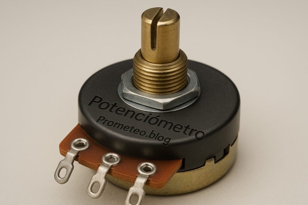
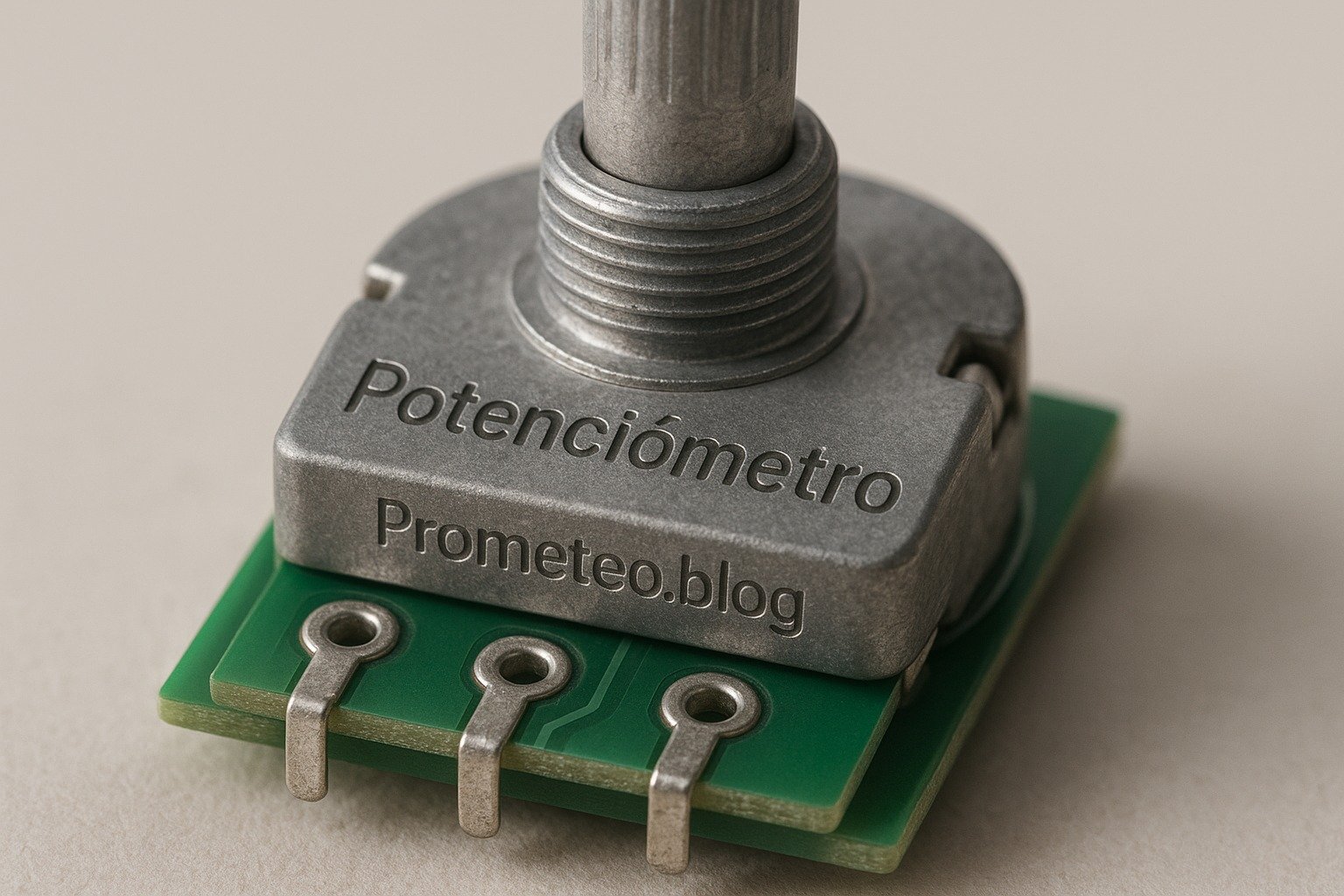
A potentiometer, commonly referred to as a pot, is an electrical component used to measure and control voltage levels in a circuit. It consists of three terminals: two connected to a resistive element, and the third connected to a wiper that moves across the resistive material. By adjusting the position of the wiper, you can vary the resistance between the terminals, thereby controlling the output voltage.
Applications of Potentiometers
The typical applications of potentiometers are vast and varied. They are found in audio equipment, where they function as volume controls, in televisions for brightness adjustment, and in various types of sensors. In essence, whenever you need to adjust a voltage signal, a potentiometer might be the ideal solution. Here are some specific applications:
-
Audio Equipment: Potentiometers are commonly used as volume controls in radios, amplifiers, and mixers. By adjusting the potentiometer, users can control the loudness of the audio output.
-
Lighting Control: In dimmer switches, potentiometers allow users to adjust the brightness of lights. This application is particularly useful in creating mood lighting or saving energy.
-
Sensor Calibration: In various sensors, such as temperature or pressure sensors, potentiometers can be used to calibrate the sensor output, ensuring accurate readings.
-
Control Systems: In industrial applications, potentiometers are often used in control systems to adjust parameters such as speed, position, and pressure.
How It Works
To understand how a potentiometer works, let’s break it down into simpler terms. When you turn the knob of a potentiometer, you are essentially changing the position of the wiper along the resistive material. This movement changes the resistance that the wiper experiences, effectively altering how much voltage is allowed to pass through.
For example, if you have a potentiometer connected to a 9 V battery, turning the knob to one side might allow only 3 V to pass through, while turning it to the other side allows the full 9 V. This ability to adjust voltage levels makes potentiometers incredibly versatile in electronic circuits.
Moreover, potentiometers can be linear or logarithmic. Linear pots change resistance uniformly with knob rotation, while logarithmic pots change resistance in a way that is more natural for human perception, often used in audio applications. This distinction is important when choosing the right potentiometer for your project.
Types of Potentiometers
There are several types of potentiometers based on their physical construction and intended use. Some of the most common types include:
-
Rotary Potentiometers: These have a knob that you turn to adjust resistance. They are often used in volume controls and are the most recognizable type of potentiometer.
-
Linear Potentiometers: These have a slider that you move to adjust resistance. They are commonly found in devices like mixing consoles and are useful for applications where a linear adjustment is preferred.
-
Digital Potentiometers: These are controlled through digital signals, allowing them to be used in more complex applications, such as in microcontroller circuits. They can be interfaced with microcontrollers to create programmable resistance values.
Additionally, potentiometers can also be categorized by their resistance value, which typically ranges from a few ohms to several million ohms, depending on the application. This broad range allows for flexibility in design and function.
Key Parameters
When selecting a potentiometer for your project, it is essential to consider several key parameters that can affect performance. These parameters include resistance value, power rating, tolerance, and more. The following table summarizes some typical values and their ranges:
| Parameter | Typical | Range | Unit | Note |
|---|---|---|---|---|
| Resistance Value | 10 kΩ | 1 Ω – 10 MΩ | Ω | Standard for audio control |
| Power Rating | 0.25 W | 0.1 W – 2 W | W | Determines heat dissipation |
| Tolerance | 20% | 5% – 20% | % | Variability in resistance |
| Temperature Coefficient | 100 ppm/°C | 50 – 200 ppm/°C | ppm/°C | Stability with temperature |
| Shaft Length | 25 mm | 10 mm – 50 mm | mm | Affects mounting options |
| Number of Turns | 1 | 1 – 3 | — | Number of full rotations |
| Mounting Type | Panel | Panel, PCB | — | Installation method |
| Operating Life | 50,000 cycles | 20,000 – 100,000 cycles | — | Durability under use |
Understanding Each Parameter
-
Resistance Value: This is the primary specification that determines how much resistance the potentiometer can provide. Selecting the appropriate resistance value is crucial for your application, especially in audio circuits where too high or too low a value can affect sound quality.
-
Power Rating: The power rating indicates how much power the potentiometer can handle before it risks damage. It is essential to choose a potentiometer with a power rating that exceeds the expected power in your circuit to ensure reliability and longevity.
-
Tolerance: Tolerance indicates how much the actual resistance can vary from the stated value. A lower tolerance means more precision, which is vital in applications requiring accurate voltage levels.
-
Temperature Coefficient: This parameter indicates how much the resistance changes with temperature. A lower temperature coefficient means the potentiometer will maintain its resistance value more consistently across temperature variations.
-
Shaft Length and Mounting Type: These parameters affect how the potentiometer can be physically integrated into your project. Depending on your design, you may need a specific shaft length or mounting type.
-
Operating Life: This parameter indicates how many cycles of use the potentiometer can withstand before it starts to fail. For applications that require frequent adjustments, a potentiometer with a higher operating life is advisable.
Hands-on practical project: Adjustable LED Dimmer
Goal: Control the brightness of an LED using a potentiometer to adjust voltage in a simple circuit, verifying the LED brightness changes proportionally with the potentiometer position.
Estimated time: 45 minutes
Materials
- 1 × 10 kΩ potentiometer — To vary resistance and control brightness.
- 1 × LED (any color) — The light source to be dimmed.
- 1 × 220 Ω resistor — To limit current through the LED.
- 1 × 9 V battery — Power source for the circuit.
- 1 × breadboard — For easy assembly of components.
- 2 × jumper wires (red and black) — For connections in the circuit.
- 1 × multimeter — To check voltage levels if needed.
Step-by-step build
- Connect LED and Resistor: Begin by inserting the LED into the breadboard. The longer leg (anode) should go into a separate row. Connect a 220 Ω resistor from the shorter leg (cathode) of the LED to another row on the breadboard. This resistor is crucial as it prevents excessive current from damaging the LED.
-
Check: Ensure the LED is positioned correctly with the right polarity. The anode should connect to the positive side, while the cathode connects to the resistor.
-
Insert the Potentiometer: Place the potentiometer on the breadboard. The potentiometer has three terminals; connect the left terminal to the positive terminal of the battery and the right terminal to the cathode of the LED where the resistor connects. The middle terminal will be used to vary the voltage.
-
Check: Verify that the terminals are correctly positioned and securely connected. A loose connection could lead to inconsistent performance.
-
Power Connections: Connect the positive terminal of the 9 V battery to the left terminal of the potentiometer, and connect the negative terminal of the battery to the row where the cathode of the LED is connected through the resistor. This setup ensures that the potentiometer can control the voltage applied to the LED.
-
Check: Ensure that the battery is connected properly and securely to the circuit. A faulty connection may prevent the circuit from functioning.
-
Final Wiring: Now connect the middle terminal of the potentiometer to the anode of the LED. This connection allows the potentiometer to control the voltage reaching the LED, thus adjusting its brightness.
- Check: Confirm that all connections are secure and correctly placed. A thorough check can prevent troubleshooting later.
Testing and validation
- Test the Circuit: Once everything is connected, turn the potentiometer knob slowly. Observe the LED brightness changing as you adjust the potentiometer. If the LED lights up and dims smoothly, the circuit is functioning as intended.
- Check: Verify that the LED brightness varies with potentiometer adjustment. If the brightness does not change, revisit your connections.
Extend the project
-
Add More LEDs: You can enhance your project by adding more LEDs in parallel and observing their combined brightness adjustments. This will help you understand how multiple components interact in a circuit.
-
Use Higher-Power Resistors: Experiment with using a higher-power resistor to control larger LEDs. This can be an excellent exercise in understanding how different components work together.
-
Integrate a Microcontroller: For more advanced users, consider integrating a microcontroller to make the brightness control programmable. This can open the door to more complex applications, such as automated lighting systems.
Safety
-
Always ensure the circuit is powered down before making adjustments. This precaution will help prevent accidental shorts or shocks.
-
Use a resistor to prevent LED burnout. LEDs are sensitive to current, and using a resistor is crucial to protect them.
-
Double-check polarity before powering the circuit. Incorrect polarity can damage the LED and other components in the circuit.
Common mistakes and how to avoid them
-
Wrong Polarity: Always double-check the LED and battery connections. LEDs have a specific polarity, and connecting them backward can cause them to fail.
-
Exceeding Current Ratings: Use appropriate resistors to prevent LED damage. If the current exceeds the LED’s rating, it can burn out quickly.
-
Loose Connections: Ensure all components are firmly connected to avoid intermittent issues. Loose connections can lead to erratic behavior in the circuit.
-
Ignoring Tolerance: Be aware of potentiometer tolerance values for accurate performance. Using a potentiometer with a high tolerance can lead to unexpected results.
-
Miscalculating Resistance: Use a multimeter to verify resistance settings. This step is crucial for ensuring that the circuit operates within the desired parameters.
Conclusion
Potentiometers are essential components that play a crucial role in adjusting voltage levels in various applications. Understanding how to work with them, as demonstrated in the hands-on project, enhances your skills in electronics. You can create more complex circuits and applications by experimenting with potentiometers. The ability to control voltage and resistance opens up a world of possibilities in your electronic projects. Don’t hesitate to explore further and get hands-on experience! More information at prometeo.blog
Third-party readings
- POTENCIÓMETRO – Microbit
- Raspberry Pi Pico: lectura de entradas analógicas (MicroPython)
- A23. Control de un motor DC con potenciómetro – Guía de trabajo para micro:bit
Find this product and/or books on this topic on Amazon
As an Amazon Associate, I earn from qualifying purchases. If you buy through this link, you help keep this project running.
Quick Quiz

Telecommunications Electronics Engineer and Computer Engineer (official degrees in Spain).