Introduction
One day, while working on a home automation project, I realized how essential relays are in controlling high-voltage devices. I remember the first time I successfully used a relay to turn on a light bulb remotely. It was a small victory, but it sparked my interest in exploring the world of relays further. Relays are fascinating components that bridge the gap between low-voltage control circuits and high-voltage loads, making them invaluable in various applications.
In this tutorial, we will delve deeper into the world of relays, exploring their functions, applications, and the science behind how they operate. We’ll also engage in a hands-on project to reinforce your understanding of relays and their practical uses. By the end of this tutorial, you will have a comprehensive understanding of relays, their key parameters, and how to use them safely and effectively in your electronic projects.
What it’s used for and how it works
Relays play a crucial role in modern electronics, allowing low-voltage circuits to control high-voltage devices safely. Essentially, a relay is an electromagnetic switch that uses a small amount of current to control a larger current. This feature is vital in various applications, from home appliances to industrial machinery.
How Relays Work
At the core of a relay is an electromagnet. When electrical current flows through the coil of wire wrapped around the electromagnet, it creates a magnetic field. This magnetic field attracts a lever arm, which then opens or closes a set of contacts. These contacts can either interrupt the flow of electricity in a circuit or complete it, depending on the relay’s design.
Let’s break this down further:
– Electromagnetic Coil: This coil is responsible for generating the magnetic field. When you apply voltage across it, it creates a magnetic force. The amount of current needed to energize this coil is typically low, which is ideal for controlling high-power devices.
– Armature: This is a movable part of the relay that is influenced by the magnetic field generated by the coil. The armature moves to either connect or disconnect the contacts, thus controlling the flow of electricity.
– Contacts: These are the conductive paths that close or open based on the position of the armature. Relays can be designed with normally open (NO) contacts, which close when the relay is activated, or normally closed (NC) contacts, which open when the relay is activated.
Applications of Relays
Relays are utilized in various applications, including:
– Home Automation: Control lights and appliances remotely or via smart devices. For example, you can set up a relay to turn on your garden lights at sunset, enhancing both convenience and security.
– Automotive: Manage high-current devices like starters and motors. In modern vehicles, relays are used extensively to control functions such as headlights, windshield wipers, and power windows.
– Industrial Control Systems: Automate machinery functions in manufacturing. Relays can be used to start and stop motors, control conveyor belts, or activate safety systems.
– Telecommunications: Switch signals in communication equipment. Relays can be found in telephone exchanges, helping to route calls and manage data traffic.
Moreover, relays can be used for safety purposes. For instance, they can isolate high voltage from low voltage circuits, protecting sensitive components. This isolation is crucial in protecting devices and ensuring user safety.
Types of Relays
There are several types of relays, each designed for specific applications:
– Electromechanical Relays (EMR): The most common type, which uses electromagnetic coils to operate. They are widely used in various applications due to their reliability and simplicity.
– Solid-state Relays (SSR): Use semiconductor devices to switch without moving parts, providing faster response times and longer lifespans. SSRs are ideal for applications requiring high-speed switching and minimal wear.
– Reed Relays: Utilize reed switches encased in a glass tube, which are activated by the magnetic field of the coil. These relays are known for their compact size and low power consumption.
Advantages of Using Relays
- Isolation: They provide electrical isolation between the control and load circuits, enhancing safety. This isolation helps prevent high voltages from damaging sensitive control circuits.
- Control High Loads: Relays can switch large currents and voltages, making them suitable for heavy-duty applications. For instance, they can control industrial machinery or heating systems.
- Multiple Circuits: A single relay can control multiple circuits, reducing the complexity of wiring. This feature is particularly useful in automating home appliances where multiple devices need to be controlled by a single command.
- Versatility: They can be used in both AC and DC applications. This versatility allows relays to be employed in a wide range of electronic systems.
Limitations of Relays
However, relays also have limitations:
1. Speed: They are slower than solid-state devices due to mechanical movement. This can be a disadvantage in applications that require rapid switching.
2. Wear and Tear: Electromechanical relays may wear out over time due to contact bouncing. This wear can lead to reduced reliability and necessitate replacement.
3. Size: They can occupy more space compared to solid-state solutions. In compact designs, the physical size of relays may pose challenges.
In summary, relays are indispensable components in various electronic systems. They provide a safe and efficient means of controlling high-power devices while isolating sensitive circuits. Understanding how they work and their various applications will enable you to leverage their capabilities effectively in your projects.
Key parameters
| Parameter | Typical | Range | Unit | Note |
|---|---|---|---|---|
| Coil Voltage | 12 | 5 – 24 | V | Common control voltage range |
| Contact Rating | 10 | 1 – 30 | A | Maximum current for contacts |
| Switching Voltage | 250 | 5 – 300 | V | Maximum voltage across contacts |
| Coil Resistance | 400 | 100 – 1000 | Ω | Resistance of coil winding |
| Mechanical Life | 10,000 | 1,000 – 20,000 | cycles | Expected lifespan of relay |
| Electrical Life | 1,000 | 100 – 10,000 | cycles | Expected lifespan under load |
| Insulation Resistance | 100 | 10 – 1000 | MΩ | Resistance between contacts and coil |
| Operating Speed | 10 | 5 – 20 | ms | Time taken to switch contacts |
Understanding these parameters is crucial when selecting a relay for your project. For example, if you are controlling a device that requires a high switching voltage, you need to ensure that the relay you choose can handle that voltage without failure. Similarly, the contact rating is essential for ensuring that the relay can handle the current required by the load without overheating or failing.
Hands-on practical project: Control a 230 V light bulb with a relay
Goal: Control a 230 V light bulb using a relay to switch it on/off with a 5 V GPIO, verifying the bulb turns on/off as intended.
Estimated time: 60 minutes
Materials
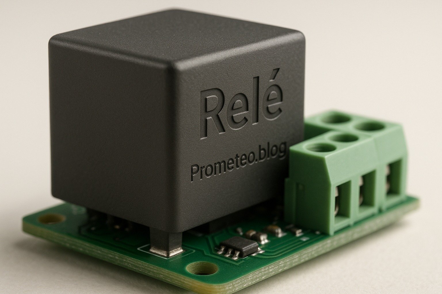
- 1 × Relay — SPDT relay for switching
- 1 × Light Bulb — 230 V rated bulb for testing
- 1 × Socket — Standard socket for the light bulb
- 1 × Power Supply — 230 V AC supply for the bulb
- 1 × GPIO Board — 5 V control from a microcontroller
- 1 × Diode — 1N4007 for flyback protection
- 1 × Resistor — 1 kΩ for GPIO pull-down
- 2 × Jumper wires — 1 red and 1 black for connections
Step-by-step build
- Connect the Relay Coil: Connect one terminal of the relay coil to a GPIO pin on the microcontroller and the other terminal to the ground. This setup allows the GPIO to energize the relay when it goes high.
-
Check: Ensure proper connections and GPIO pin configuration.
-
Add Flyback Diode: Connect the diode in parallel with the relay coil, ensuring the cathode (striped end) is connected to the positive terminal. This will protect the GPIO from voltage spikes when the relay is de-energized.
-
Check: Verify the orientation of the diode.
-
Wire the Light Bulb: Connect one terminal of the light bulb socket to the common terminal of the relay. Connect the normally open (NO) terminal to the live wire of the power supply. Connect the other terminal of the light bulb to the neutral wire.
-
Check: Ensure the bulb is rated for 230 V.
-
Add Pull-down Resistor: Connect a 1 kΩ resistor between the GPIO pin and ground. This pull-down resistor ensures the GPIO pin reads low when not driven high, preventing accidental relay activation.
-
Check: Measure the voltage at the GPIO pin to confirm it is low.
-
Power the Circuit: Connect the power supply to the light bulb socket. Ensure all connections are secure and insulated to prevent short circuits.
-
Check: Inspect all connections for safety and reliability.
-
Test the Relay: Program your microcontroller to send a high signal to the GPIO pin for a few seconds and then low. Observe the light bulb; it should turn on when the signal is high and turn off when it’s low.
- Check: Confirm the light bulb’s operation matches the GPIO signal.
Testing and validation
- Run the Microcontroller Program: Upload the code to your microcontroller and run it. Ensure it toggles the GPIO pin between high and low states.
-
Check: Observe the light bulb’s response.
-
Verify the Connections: If the light bulb does not operate as expected, double-check all connections and the wiring of the relay.
- Check: Ensure the relay clicks when activated.
Extend the project
- Integrate a remote control to switch the light bulb on/off. You could use RF modules or Wi-Fi-enabled microcontrollers to achieve this.
- Use a smartphone app to control the relay wirelessly. Platforms like Blynk or custom-built apps can be utilized.
- Add a light sensor to automate the bulb based on ambient light levels. This will allow the light to turn on automatically at dusk and off at dawn.
Safety
- Always work with the power supply disconnected when wiring.
- Use insulated tools to prevent electric shocks.
- Ensure the relay is rated for the voltage and current of the bulb.
- Avoid touching live wires or terminals when powered.
- Be cautious of heat generated by the relay during operation.
Common mistakes and how to avoid them
- Incorrect Relay Wiring: Verify the relay’s pinout before wiring. A mistake here could lead to malfunction or damage.
- No Flyback Diode: Always use a diode across the coil to prevent damage to the microcontroller from voltage spikes.
- Overloading the Relay: Ensure the load does not exceed the relay’s rating. If in doubt, choose a relay with a higher rating to provide a safety margin.
- Neglecting Safety Precautions: Always prioritize safety when working with AC voltage. Double-check your setup before powering it on.
- Poor Connections: Secure all connections to avoid intermittent issues. Loose connections can lead to unreliable operation.
Conclusion
In this tutorial, you learned about relays, their working principles, applications, and how to implement a practical project to control a 230 V light bulb. Understanding relays can significantly enhance your electronics projects by allowing control over high-power devices safely. So, gather your materials and start experimenting with relays today! More information at prometeo.blog
Third-party readings
- MicroPython: Servidor web del módulo de relé ESP32/ESP8266 (dispositivos de CA) – Micro Tutos
- Relé para MICRO:BIT de Monk Make – RobotShop
- Tutorial módulo Relé Cap 06 -Tauxi Comercializadora – Tauxi
Find this product and/or books on this topic on Amazon
As an Amazon Associate, I earn from qualifying purchases. If you buy through this link, you help keep this project running.
Quick Quiz

Telecommunications Electronics Engineer and Computer Engineer (official degrees in Spain).