
Level: Basic – Build a light interruption sensor system to detect objects moving on a line.
Objective and use case
In this practical case, you will build an optical barrier using a photoresistor (LDR) and an operational amplifier configured as a voltage comparator. The circuit detects when an opaque object interrupts a continuous beam of light, triggering a signal that can be counted or processed.
Why it is useful:
* Industrial automation: Used to count products moving on a conveyor belt.
* Safety barriers: Detects if a person or object crosses a dangerous boundary.
* Intruder alarms: Triggers a warning when a beam of invisible or visible light is broken.
* Parking systems: Detects the presence of a vehicle in a specific spot.
Expected outcome:
* State A (Light path clear): The sensor receives light, and the output indicator (Red LED) remains OFF (Logic Low).
* State B (Object detected): The object blocks the light, increasing LDR resistance. The output indicator turns ON (Logic High).
* Signal Threshold: The comparator switches states when the sensor voltage crosses the adjustable reference voltage (approx. 2.5 V).
Target audience: Level Basic
Materials
- V1: 5 V DC power supply, function: main circuit power.
- R1: 10 kΩ resistor, function: voltage divider top for reference.
- R2: 10 kΩ resistor, function: voltage divider bottom for reference.
- R3: 10 kΩ resistor, function: pull-up resistor for the sensor node.
- R4: Photoresistor (LDR), function: light detection sensor.
- R5: 330 Ω resistor, function: current limiting for output indicator LED.
- R6: 330 Ω resistor, function: current limiting for emitter LED.
- D1: White LED, function: light emitter (simulates the beam source).
- D2: Red LED, function: output indicator (object detected).
- U1: LM358 or similar OpAmp, function: voltage comparator.
Wiring guide
This circuit relies on comparing two voltages: a fixed reference (V_REF) and a variable sensor voltage (V_SENSE).
Power Connections
* V1 (+) connects to node VCC.
* V1 (-) connects to node 0 (GND).
* U1 (Pin 8 / VCC) connects to VCC.
* U1 (Pin 4 / GND) connects to 0.
Reference Voltage (V_REF)
* R1 connects between VCC and V_REF.
* R2 connects between V_REF and 0.
* U1 (Pin 2 / Inverting Input) connects to V_REF.
* Note: This sets a fixed threshold of 2.5 V.
Sensor Voltage (V_SENSE)
* R3 connects between VCC and V_SENSE.
* R4 (LDR) connects between V_SENSE and 0.
* U1 (Pin 3 / Non-Inverting Input) connects to V_SENSE.
* Logic: When light is blocked, R4 resistance increases, V_SENSE rises. If V_SENSE > V_REF, Output goes High.
Light Emitter (Source)
* R6 connects between VCC and NODE_EMIT.
* D1 (Anode) connects to NODE_EMIT.
* D1 (Cathode) connects to 0.
* Place D1 physically facing R4 (LDR).
Output Stage
* U1 (Pin 1 / Output) connects to V_OUT.
* R5 connects between V_OUT and NODE_LED.
* D2 (Anode) connects to NODE_LED.
* D2 (Cathode) connects to 0.
Conceptual block diagram
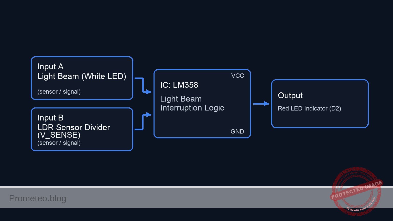
Schematic
[ INPUTS / SENSORS ]                     [ LOGIC / PROCESSING ]             [ OUTPUTS ]

    [ LIGHT SOURCE ]
    [ VCC -> R6 -> D1 (White) ]
             |
      (Light Beam Path)
             |
             V
    [ SENSOR DIVIDER ]
    [ VCC -> R3 -> Node -> R4 ] --(V_SENSE)-->+----------------+
    [ (R4=LDR, varies w/ light)]              |   Pin 3 (+)    |
                                              |                |
                                              |    U1 LM358    |
                                              |   (Comparator) | --(Pin 1)--> [ R5 (330) ] --> [ D2 (Red LED) ] --> GND
                                              |                |
    [ REFERENCE DIVIDER ]                     |                |
    [ VCC -> R1 -> Node -> R2 ] --(V_REF)---->|   Pin 2 (-)    |
    [ (Fixed 2.5 V Threshold)  ]               +----------------+
Measurements and tests
- Reference Check: Use a multimeter to measure the voltage between
V_REFand0. It should be approximately 2.5 V (half of VCC). - Light Condition (Clear Path): Ensure the Emitter LED (D1) shines on the LDR (R4). Measure
V_SENSE. It should be lower thanV_REF(e.g., < 2.0 V). The Output LED (D2) should be OFF. - Dark Condition (Object Detected): Place an object (cardboard or finger) between D1 and R4. Measure
V_SENSE. It should rise higher thanV_REF(e.g., > 3.0 V). The Output LED (D2) should turn ON. - Comparator Output: Measure
V_OUTrelative to0. In the «Dark» state, it should be close to 3.5 V – 4 V (High). In the «Light» state, it should be close to 0 V (Low).
SPICE netlist and simulation
Reference SPICE Netlist (ngspice) — excerptFull SPICE netlist (ngspice)
* Practical case: Object counter on conveyor belt

* -----------------------------------------------------------------------------
* Power Supply
* Wiring: V1 (+) to VCC, V1 (-) to 0 (GND)
* -----------------------------------------------------------------------------
V1 VCC 0 DC 5

* -----------------------------------------------------------------------------
* Reference Voltage Divider
* Wiring: R1 between VCC and V_REF, R2 between V_REF and 0
* Function: Sets threshold voltage (approx 2.5V)
* -----------------------------------------------------------------------------
R1 VCC V_REF 10k
R2 V_REF 0 10k

* -----------------------------------------------------------------------------
* Sensor Network
* Wiring: R3 between VCC and V_SENSE, R4 (LDR) between V_SENSE and 0
* Simulation Note: R4 is modeled as a behavioral resistor to simulate the
* ... (truncated in public view) ...
Copy this content into a .cir file and run with ngspice.
* Practical case: Object counter on conveyor belt

* -----------------------------------------------------------------------------
* Power Supply
* Wiring: V1 (+) to VCC, V1 (-) to 0 (GND)
* -----------------------------------------------------------------------------
V1 VCC 0 DC 5

* -----------------------------------------------------------------------------
* Reference Voltage Divider
* Wiring: R1 between VCC and V_REF, R2 between V_REF and 0
* Function: Sets threshold voltage (approx 2.5V)
* -----------------------------------------------------------------------------
R1 VCC V_REF 10k
R2 V_REF 0 10k

* -----------------------------------------------------------------------------
* Sensor Network
* Wiring: R3 between VCC and V_SENSE, R4 (LDR) between V_SENSE and 0
* Simulation Note: R4 is modeled as a behavioral resistor to simulate the
* changing resistance of an LDR when an object blocks the light.
* -----------------------------------------------------------------------------
R3 VCC V_SENSE 10k

* R4 (LDR) Implementation:
* Resistance = 1k (Light/No Object) to 100k (Dark/Object Detected)
* Controlled by dummy voltage source V_OBJ_CTRL
R4 V_SENSE 0 R='1k + 99k / (1 + exp(-50 * (V(V_OBJ_CTRL) - 2.5)))'

* -----------------------------------------------------------------------------
* Light Emitter (Source)
* Wiring: R6 between VCC and NODE_EMIT, D1 Anode to NODE_EMIT, Cathode to 0
* -----------------------------------------------------------------------------
R6 VCC NODE_EMIT 330
D1 NODE_EMIT 0 D_WHITE

* -----------------------------------------------------------------------------
* Comparator (U1: LM358)
* Wiring: Pin 8=VCC, Pin 4=0, Pin 3=V_SENSE (+), Pin 2=V_REF (-), Pin 1=V_OUT
* -----------------------------------------------------------------------------
XU1 V_SENSE V_REF VCC 0 V_OUT LM358_COMP

* -----------------------------------------------------------------------------
* Output Stage
* Wiring: R5 between V_OUT and NODE_LED, D2 Anode to NODE_LED, Cathode to 0
* -----------------------------------------------------------------------------
R5 V_OUT NODE_LED 330
D2 NODE_LED 0 D_RED

* -----------------------------------------------------------------------------
* Dynamic Stimuli (Object Simulation)
* This source drives the behavioral LDR (R4).
* Logic: 0V = Clear (Light), 5V = Object (Dark)
* Timing: Wait 50us, Pulse High for 100us, Repeat every 300us
* -----------------------------------------------------------------------------
V_OBJ V_OBJ_CTRL 0 PULSE(0 5 50u 10u 10u 100u 300u)

* -----------------------------------------------------------------------------
* Models and Subcircuits
* -----------------------------------------------------------------------------
.model D_WHITE D(IS=1e-14 N=4 RS=10) ; High Vf simulation for White LED
.model D_RED D(IS=1e-12 N=2 RS=5)    ; Standard Red LED

* Behavioral OpAmp Subcircuit (Comparator)
* Pinout Order: Non-Inv(+), Inv(-), VCC, GND, Output
.subckt LM358_COMP P M V_POS V_NEG OUT
  * Sigmoid function for robust switching behavior (Rail-to-Rail logic approx)
  * V(OUT) approaches V_POS when P > M, V_NEG when P < M
  B1 OUT 0 V = V(V_POS) * (1 / (1 + exp(-100 * (V(P) - V(M)))))
.ends

* -----------------------------------------------------------------------------
* Analysis Directives
* -----------------------------------------------------------------------------
.op
.tran 1u 500u

* Print required signals for batch processing
.print tran V(V_SENSE) V(V_REF) V(V_OUT) V(V_OBJ_CTRL)
Simulation Results (Transient Analysis)

Show raw data table (1064 rows)
Index   time            v(v_sense)      v(v_ref)        v(v_out)
0	0.000000e+00	4.545455e-01	2.500000e+00	7.345271e-89
1	1.000000e-08	4.545455e-01	2.500000e+00	7.345271e-89
2	2.000000e-08	4.545455e-01	2.500000e+00	7.345271e-89
3	4.000000e-08	4.545455e-01	2.500000e+00	7.345271e-89
4	8.000000e-08	4.545455e-01	2.500000e+00	7.345271e-89
5	1.600000e-07	4.545455e-01	2.500000e+00	7.345271e-89
6	3.200000e-07	4.545455e-01	2.500000e+00	7.345271e-89
7	6.400000e-07	4.545455e-01	2.500000e+00	7.345271e-89
8	1.280000e-06	4.545455e-01	2.500000e+00	7.345271e-89
9	2.280000e-06	4.545455e-01	2.500000e+00	7.345271e-89
10	3.280000e-06	4.545455e-01	2.500000e+00	7.345271e-89
11	4.280000e-06	4.545455e-01	2.500000e+00	7.345271e-89
12	5.280000e-06	4.545455e-01	2.500000e+00	7.345271e-89
13	6.280000e-06	4.545455e-01	2.500000e+00	7.345271e-89
14	7.280000e-06	4.545455e-01	2.500000e+00	7.345271e-89
15	8.280000e-06	4.545455e-01	2.500000e+00	7.345271e-89
16	9.280000e-06	4.545455e-01	2.500000e+00	7.345271e-89
17	1.028000e-05	4.545455e-01	2.500000e+00	7.345271e-89
18	1.128000e-05	4.545455e-01	2.500000e+00	7.345271e-89
19	1.228000e-05	4.545455e-01	2.500000e+00	7.345271e-89
20	1.328000e-05	4.545455e-01	2.500000e+00	7.345271e-89
21	1.428000e-05	4.545455e-01	2.500000e+00	7.345271e-89
22	1.528000e-05	4.545455e-01	2.500000e+00	7.345271e-89
23	1.628000e-05	4.545455e-01	2.500000e+00	7.345271e-89
... (1040 more rows) ...
Common mistakes and how to avoid them
- Swapping OpAmp inputs: Connecting the Reference to the Non-Inverting (+) input instead of the Inverting (-) input will reverse the logic (LED turns OFF when object is detected). Ensure
V_SENSEgoes to the Non-Inverting (+) pin for «Dark Detection». - Ambient Light interference: The LDR is very sensitive. If the room is bright, the «Dark» state might not be dark enough to trigger the threshold. Use a small tube or tape to shield the LDR.
- Incorrect LDR placement: If the LDR (R4) is placed in the top leg of the voltage divider (swapped with R3), the logic is inverted. Ensure R4 connects to Ground (
0).
Troubleshooting
- Output LED never turns ON:
- Check if the object actually blocks the light completely.
- Measure
V_SENSE. If it never exceeds 2.5 V, increase the value of R3 (e.g., to 22 kΩ) to raise the voltage sensitivity.
- Output LED never turns OFF:
- The LDR might be receiving insufficient light from the Emitter.
- Check alignment of D1 and R4.
- Measure
V_REF. If R1 is disconnected,V_REFmight be 0 V, causing the output to stay High.
- Output flickers:
- The light source might be unstable, or the voltage is hovering exactly at the threshold. Add a decoupling capacitor (e.g., 100 nF) across the power rails near the OpAmp.
Possible improvements and extensions
- Adjustable Sensitivity: Replace R1 or R2 with a 10 kΩ potentiometer. This allows you to fine-tune the
V_REFthreshold to work in different ambient light conditions. - Hysteresis (Schmidt Trigger): Add a high-value feedback resistor (e.g., 1 MΩ) between the Output (
V_OUT) and the Non-Inverting input (V_SENSE). This prevents the LED from flickering if the object moves slowly across the beam.
More Practical Cases on Prometeo.blog
Find this product and/or books on this topic on Amazon
As an Amazon Associate, I earn from qualifying purchases. If you buy through this link, you help keep this project running.
Quick Quiz

Telecommunications Electronics Engineer and Computer Engineer (official degrees in Spain).

