
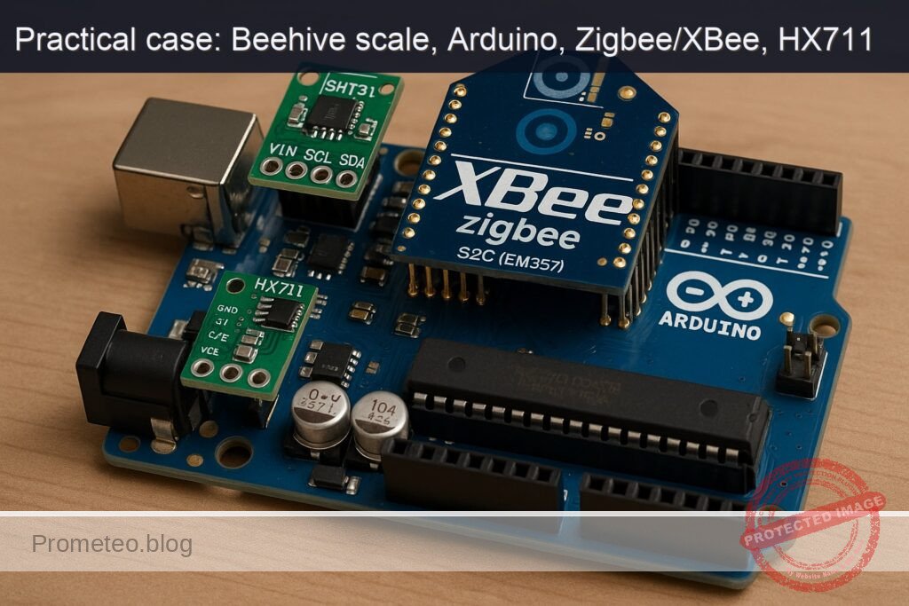
Objective and use case
What you’ll build: This project involves creating a Zigbee beehive weight sensor using an Arduino Uno R3, HX711 load cell amplifier, and XBee Zigbee S2C module. The system will report the weight of the beehive and monitor ambient conditions.
Why it matters / Use cases
- Beekeepers can monitor hive weight remotely, allowing them to assess honey production and hive health without disturbing the bees.
- Data on temperature and humidity inside the hive can help prevent swarming and ensure optimal conditions for the bees.
- Integrating with existing smart farming systems can provide insights into hive performance and environmental conditions.
- Real-time monitoring can alert beekeepers to significant changes in hive weight or environmental conditions, enabling timely interventions.
Expected outcome
- Accurate weight measurements of the beehive with a precision of ±0.1 kg.
- Temperature readings within ±0.5°C and humidity readings within ±3% relative humidity.
- Transmission of telemetry data every 10 seconds over the Zigbee network.
- Latency of less than 1 second for data updates from the beehive to the coordinator.
Audience: Experienced makers; Level: Advanced
Architecture/flow: Arduino Uno R3 with HX711 and SHT31 sensors connected to XBee Zigbee S2C, transmitting data to a Zigbee coordinator for monitoring.
Advanced Hands‑On: Zigbee Beehive Weight Sensing with Arduino Uno R3 + XBee Zigbee S2C (EM357) + HX711 + SHT31
This advanced, end‑to‑end build turns an Arduino Uno R3 into a Zigbee node that reports beehive weight and ambient conditions over an XBee Zigbee S2C (EM357) link. The HX711 reads a 4‑wire load cell under the hive, the SHT31 measures temperature/humidity inside the hive, and the XBee S2C (in API mode) transmits compact telemetry frames to a Zigbee coordinator.
The tutorial is opinionated and precise on wiring, code, Zigbee API framing, Arduino CLI build commands, and validation—so you can reproduce the system with minimal guesswork.
Prerequisites
- Experience level: Advanced (you are comfortable with UART/I2C, Arduino libraries, Zigbee API frames, and serial tooling).
- Operating systems supported:
- Linux/macOS/Windows for Arduino CLI (tested on Linux).
- A separate computer/USB adapter to host a Zigbee Coordinator and to verify received frames.
- Software:
- Arduino CLI 0.35.2 or newer (tested on 0.35.2).
- Python 3.9+ with pyserial (optional, for validation).
- Digi XCTU (GUI) to ensure XBee firmware roles (Coordinator/Router) are correctly loaded. You can use any OS version of XCTU.
- Hardware skill:
- Basic soldering/crimping.
- Ability to safely calibrate a load cell using known weights.
- Note on Zigbee roles:
- You need two XBee Zigbee S2C modules: one on the Arduino Uno R3 (Router API firmware), and one on a PC as Coordinator (Coordinator API firmware). If you only have one, you’ll need another Zigbee coordinator or gateway capable of receiving raw RF data frames from the XBee.
Materials (exact models)
- Arduino Uno R3 (ATmega328P, 5 V).
- XBee Zigbee S2C (EM357) module:
- Model: Digi XBee Zigbee 3 (S2C) 2.4 GHz, EM357, Through‑Hole, e.g., XB24CZ7PIT‑004 (or equivalent S2C TH footprint).
- Role/firmware on PC: “Zigbee Coordinator API”
- Role/firmware on Arduino: “Zigbee Router API”
- XBee Arduino shield with level shifting and 3.3 V regulation:
- SparkFun XBee Shield (WRL‑12847) or equivalent with DLINE routing option.
- Load cell (4‑wire), 50 kg recommended:
- Example: TAL220B‑50 kg (bar type).
- HX711 24‑bit ADC breakout for load cells:
- Example: SparkFun Load Cell Amplifier – HX711 (SEN‑13879) or equivalent “green board”.
- SHT31 digital temperature/humidity sensor breakout:
- Adafruit SHT31‑D (Product ID 2857), supports 3.3–5 V.
- Power:
- 5 V regulated supply capable of 500 mA minimum (bench PSU for lab, or field supply with DC‑DC buck).
- Interconnects:
- Female‑female and male‑female jumpers, screw terminals as needed.
- Shielded cable for load cell if installed long distance.
- Optional for validation:
- XBee Explorer USB (Digi or SparkFun) for the Coordinator side.
- Known calibration weights (e.g., 5 kg, 10 kg).
Setup / Connection
1) XBee firmware roles and basic parameters
Ensure you have two XBee Zigbee S2C modules:
- Coordinator side (on PC): firmware “Zigbee Coordinator API”
- Node on Arduino: firmware “Zigbee Router API”
Use Digi XCTU (GUI) to load these firmwares if necessary. Then set consistent parameters:
- PAN ID: ID = 0x1234 (example—choose one; both modules must match)
- API mode: AP = 1 (API without escapes)
- Baud rate: BD = 3 (9600 bps)
- Channel: leave default or specify CH as needed (optional)
- Node identifiers (optional): NI = HIVE‑ROUTER or HIVE‑COORD
- Write settings to flash: WR
For the Coordinator, keep DH/DL at 0; for this tutorial we will have the Router send to the Coordinator’s 64‑bit address via API 0x10 (Transmit Request). You will need the Coordinator’s 64‑bit MAC/EUI‑64; find it in XCTU (SL/SH parameters) and note it as 8 bytes for the Arduino sketch.
Example manual AT command session on the PC’s XBee (Coordinator) using a serial terminal (enter command mode with +++ and wait OK):
+++
ATRE
ATAP1
ATID1234
ATBD3
ATWR
ATCN
Repeat with appropriate params for the Router on the Arduino shield side (Router API firmware).
2) Arduino Uno R3 + shields/sensors wiring
We use the SparkFun XBee Shield (WRL‑12847) with the DLINE switch set to “DLINE” so the shield routes XBee DOUT to Arduino D2 and XBee DIN to Arduino D3. This allows using SoftwareSerial on pins 2/3 at 9600 bps.
HX711 is connected to two digital GPIOs (data and clock). SHT31 uses I2C on A4/A5.
Connection map:
| Subsystem | Exact Part | Connections (Arduino Uno R3) | Notes |
|---|---|---|---|
| XBee Zigbee S2C (EM357) on XBee Shield | Digi XBee Zigbee 3 S2C (XB24CZ7PIT‑004) + SparkFun XBee Shield WRL‑12847 | Shield stacks onto Uno. Set DLINE switch to DLINE (uses D2/D3). XBee powered by shield (3.3 V) | Ensures level shifting and correct voltage |
| HX711 | SparkFun SEN‑13879 HX711 board | VCC→5V, GND→GND, DT(DOUT)→D4, SCK→D5 | Use 4‑wire load cell: E+, E‑, A+, A‑ |
| Load cell | TAL220B‑50kg | E+→E+, E‑→E‑, A+→A+, A‑→A‑ on HX711 | Typical colors: Red E+, Black E‑, Green A+, White A‑ (verify) |
| SHT31 | Adafruit SHT31‑D (ID 2857) | VIN→5V, GND→GND, SDA→A4, SCL→A5 | Default I2C addr 0x44 |
Additional notes:
– Do not power the XBee directly from Arduino 3.3 V pin without a shield; current draw and level shifting are issues. The SparkFun shield solves both.
– Keep the load cell wiring twisted and away from noisy power lines.
– For field installs, strain‑relief all cables and protect the HX711 and boards from moisture.
Full Code (Arduino Uno R3)
This sketch:
– Initializes HX711 and SHT31.
– Periodically averages HX711 readings to compute weight in kilograms.
– Reads temperature (°C) and relative humidity (%RH) from SHT31.
– Constructs an XBee API 0x10 Transmit Request with JSON payload and sends to Coordinator’s 64‑bit address.
– Provides basic Serial diagnostics at 115200 bps and a ‘t’ command to tare the scale.
Replace DEST64 with your Coordinator’s EUI‑64 (most significant byte first) taken from XCTU.
Create the sketch folder and file:
– Folder: ~/zigbee-beehive-weight-sensing/zigbee_beehive_weight_sensing
– File: ~/zigbee-beehive-weight-sensing/zigbee_beehive_weight_sensing/zigbee_beehive_weight_sensing.ino
#include <Arduino.h>
#include <Wire.h>
#include <SoftwareSerial.h>
#include "HX711.h"
#include "Adafruit_SHT31.h"

// -------------------- Pins --------------------
static const uint8_t PIN_HX711_DT  = 4;  // D4
static const uint8_t PIN_HX711_SCK = 5;  // D5
static const uint8_t PIN_XBEE_RX   = 2;  // D2 (Arduino RX)  <- XBee DOUT
static const uint8_t PIN_XBEE_TX   = 3;  // D3 (Arduino TX)  -> XBee DIN
static const uint8_t LED_PIN       = 13; // Onboard LED

// -------------------- XBee --------------------
// Coordinator EUI-64 (replace with yours from XCTU, SH:MSBs, SL:LSBs)
uint8_t DEST64[8] = {
  0x00, 0x13, 0xA2, 0x00, 0x41, 0x52, 0x53, 0x54 // EXAMPLE PLACEHOLDER
};
// Zigbee transmit: unknown 16-bit address
static const uint16_t DEST16_UNKNOWN = 0xFFFE;
// Use API mode 1 (no escapes)
SoftwareSerial xbee(PIN_XBEE_RX, PIN_XBEE_TX); // RX, TX

// -------------------- Sensors --------------------
HX711 scale;
Adafruit_SHT31 sht31 = Adafruit_SHT31();

// Calibration: set this after your calibration step (kg per HX711 raw unit)
// Start with a guess; refine per "Validation" section.
float CAL_FACTOR = -2280.0f; // sign depends on wiring; adjust during calibration
float tareOffset = 0.0f;

unsigned long lastSendMs = 0;
const unsigned long SEND_PERIOD_MS = 30000; // 30 s
const uint8_t HX_SAMPLES = 10;

// -------------------- Helpers --------------------
uint8_t checksumXBee(const uint8_t *frameData, size_t len) {
  uint16_t sum = 0;
  for (size_t i = 0; i < len; i++) sum += frameData[i];
  return 0xFF - (sum & 0xFF);
}

void xbeeSendZigbeeTransmitRequest(const uint8_t *dest64, const uint8_t *rfData, uint16_t rfLen) {
  // Frame type 0x10 (Zigbee Transmit Request, API=1)
  // Format: 0x7E | length(2) | frame data... | checksum
  // Frame data: [0]=0x10, [1]=FrameID, [2..9]=64-bit dest, [10..11]=16-bit dest, [12]=radius, [13]=options, [14..]=RF payload
  const uint8_t FRAME_TYPE = 0x10;
  const uint8_t FRAME_ID   = 0x01;
  const uint8_t BROADCAST_RADIUS = 0x00;
  const uint8_t TX_OPTIONS = 0x00;

  const size_t FRAME_DATA_LEN = 1 + 1 + 8 + 2 + 1 + 1 + rfLen;
  uint8_t *frameData = (uint8_t*)malloc(FRAME_DATA_LEN);
  if (!frameData) return;

  size_t idx = 0;
  frameData[idx++] = FRAME_TYPE;
  frameData[idx++] = FRAME_ID;
  for (int i = 0; i < 8; i++) frameData[idx++] = dest64[i];
  frameData[idx++] = (DEST16_UNKNOWN >> 8) & 0xFF;
  frameData[idx++] = (DEST16_UNKNOWN >> 0) & 0xFF;
  frameData[idx++] = BROADCAST_RADIUS;
  frameData[idx++] = TX_OPTIONS;
  for (uint16_t i = 0; i < rfLen; i++) frameData[idx++] = rfData[i];

  uint8_t csum = checksumXBee(frameData, FRAME_DATA_LEN);

  // Send to XBee UART
  xbee.write(0x7E);
  xbee.write((FRAME_DATA_LEN >> 8) & 0xFF);
  xbee.write((FRAME_DATA_LEN >> 0) & 0xFF);
  xbee.write(frameData, FRAME_DATA_LEN);
  xbee.write(csum);

  free(frameData);
}

float readWeightKgAveraged(uint8_t samples) {
  // Average multiple readings for noise reduction
  long sum = 0;
  for (uint8_t i = 0; i < samples; i++) {
    while (!scale.is_ready()) {
      delay(2);
    }
    sum += scale.read();
  }
  long avg = sum / samples;
  float weightKg = (avg - tareOffset) / CAL_FACTOR;
  return weightKg;
}

void flashLED(uint8_t times, uint16_t onMs, uint16_t offMs) {
  for (uint8_t i = 0; i < times; i++) {
    digitalWrite(LED_PIN, HIGH);
    delay(onMs);
    digitalWrite(LED_PIN, LOW);
    delay(offMs);
  }
}

void setup() {
  pinMode(LED_PIN, OUTPUT);
  digitalWrite(LED_PIN, LOW);

  Serial.begin(115200);
  delay(50);
  Serial.println(F("Beehive Zigbee weight node boot"));

  // XBee serial
  xbee.begin(9600);
  delay(50);
  Serial.println(F("XBee UART at 9600 bps"));

  // Sensors
  Wire.begin();

  // HX711
  scale.begin(PIN_HX711_DT, PIN_HX711_SCK);
  delay(200);
  // Optional: initial tare
  if (scale.is_ready()) {
    // Take a quick baseline for tare offset
    long t = 0;
    const uint8_t N = 10;
    for (uint8_t i = 0; i < N; i++) {
      while (!scale.is_ready()) { delay(1); }
      t += scale.read();
    }
    tareOffset = t / (float)N;
    Serial.print(F("Initial tareOffset raw=")); Serial.println(tareOffset, 1);
  } else {
    Serial.println(F("HX711 not ready; check wiring."));
  }

  // SHT31
  if (!sht31.begin(0x44)) {
    Serial.println(F("SHT31 not found at 0x44. Check wiring."));
  } else {
    Serial.println(F("SHT31 init OK"));
  }

  flashLED(2, 60, 60);
}

void loop() {
  // Simple serial console commands
  if (Serial.available()) {
    char c = (char)Serial.read();
    if (c == 't') {
      // Tare current reading
      if (scale.is_ready()) {
        long t = 0;
        const uint8_t N = 15;
        for (uint8_t i = 0; i < N; i++) {
          while (!scale.is_ready()) { delay(1); }
          t += scale.read();
        }
        tareOffset = t / (float)N;
        Serial.print(F("Tared. tareOffset=")); Serial.println(tareOffset, 1);
      } else {
        Serial.println(F("HX711 not ready, cannot tare."));
      }
    } else if (c == 's') {
      Serial.print(F("Status: CAL_FACTOR=")); Serial.print(CAL_FACTOR, 4);
      Serial.print(F(" tareOffset=")); Serial.println(tareOffset, 1);
    }
  }

  unsigned long now = millis();
  if (now - lastSendMs >= SEND_PERIOD_MS) {
    lastSendMs = now;

    // Read sensors
    float weightKg = readWeightKgAveraged(HX_SAMPLES);
    float tC = NAN, rh = NAN;
    if (sht31.begin(0x44)) { // ensure it's responsive
      tC = sht31.readTemperature();
      rh = sht31.readHumidity();
    }

    // Compose compact JSON: {"ts":..., "wkg":..., "tC":..., "rh":...}
    char payload[96];
    unsigned long ts = now / 1000UL; // seconds since boot
    // constrain precision to keep payload small
    dtostrf(weightKg, 0, 2, payload); // reuse as scratch; overwritten below
    // Use snprintf to build final JSON
    // Keep under ~90 bytes for Uno SRAM comfort
    snprintf(payload, sizeof(payload),
             "{\"ts\":%lu,\"wkg\":%.2f,\"tC\":%.2f,\"rh\":%.1f}",
             ts,
             isfinite(weightKg) ? weightKg : -999.0,
             isfinite(tC) ? tC : -99.0,
             isfinite(rh) ? rh : -1.0);

    Serial.print(F("TX: ")); Serial.println(payload);

    // Send via XBee API 0x10
    xbeeSendZigbeeTransmitRequest(DEST64, (const uint8_t*)payload, (uint16_t)strlen(payload));

    flashLED(1, 40, 40);
  }
}
Key details:
– API mode is set to 1 (AP=1) on XBee (no escape processing).
– Transmit frame type is 0x10 (Zigbee Transmit Request). Coordinator receives 0x90 (Zigbee Receive Packet) frames containing the RF data.
– JSON payload kept small for SRAM headroom.
Build / Flash / Run (Arduino CLI only)
Assuming your sketch lives at:
– ~/zigbee-beehive-weight-sensing/zigbee_beehive_weight_sensing/
And your Arduino Uno R3 appears as /dev/ttyACM0 (Linux). Replace with COM3 on Windows or /dev/tty.usbmodemXXX on macOS.
Install Arduino CLI and run:
arduino-cli version
Initialize and install the AVR core:
arduino-cli core update-index
arduino-cli core install arduino:avr
Install exact library versions (tested):
arduino-cli lib install "HX711@0.7.5"
arduino-cli lib install "Adafruit SHT31 Library@2.2.0"
arduino-cli lib install "Adafruit BusIO@1.14.5"
Create the project structure (if not already):
mkdir -p ~/zigbee-beehive-weight-sensing/zigbee_beehive_weight_sensing
Compile:
arduino-cli compile \
  --fqbn arduino:avr:uno \
  ~/zigbee-beehive-weight-sensing/zigbee_beehive_weight_sensing
Identify the serial port:
arduino-cli board list
Upload (Linux example):
arduino-cli upload \
  --fqbn arduino:avr:uno \
  --port /dev/ttyACM0 \
  ~/zigbee-beehive-weight-sensing/zigbee_beehive_weight_sensing
Open a serial monitor at 115200 bps (optional):
arduino-cli monitor -p /dev/ttyACM0 -c baudrate=115200
Step‑by‑Step Validation
Follow these steps carefully, in order.
1) Verify the XBee network
- Use XCTU on the PC with the Coordinator attached via XBee Explorer USB:
- Confirm firmware role “Zigbee Coordinator API”.
- Confirm AP=1, BD=9600, ID=0x1234.
- Read and note the EUI‑64 (SH:SL). Copy to the Arduino sketch DEST64 (MSB first).
- Enable network forming (default for Coordinator); power cycle if needed.
- On the Arduino’s XBee (Router API):
- Confirm firmware role “Zigbee Router API”.
- AP=1, BD=9600, ID=0x1234.
- After power‑up, it should join the Coordinator’s network automatically (AI=0 indicates success). You can read AI in XCTU when connected to that module, or blink patterns on ASSOC LED if your shield exposes it.
2) Validate HX711 load cell wiring and baseline
- Power everything and open the Arduino serial monitor at 115200 bps.
- Observe “Initial tareOffset raw=…”.
- Place no load on the hive stand. Press ‘t’ to tare:
- Type t then Enter in the serial monitor.
- The sketch re‑averages raw counts and stores tareOffset.
- Place a known test weight (e.g., 5 kg) on the platform:
- Observe the printed “TX:” JSON every 30 s; the “wkg” will be off initially (because CAL_FACTOR is guessed).
- Calibrate CAL_FACTOR:
- Note the average raw delta: in a quick calibration variant, temporarily print raw readings. Alternatively:
- Compute current reported wkg and find ratio to actual weight.
- New CAL_FACTOR = Old CAL_FACTOR × (reported_kg / actual_kg).
- If sign is inverted, flip the sign of CAL_FACTOR.
- Update CAL_FACTOR in the sketch, rebuild, upload, and repeat until the reported weight matches within your target error (<1%).
Tip: For a rigorous approach, log “avg raw” and compute slope as kg per raw count using at least two calibration points (tare at 0 kg, and known weight W). Then CAL_FACTOR = (avgRawAtW − tareOffset) / W.
3) Validate SHT31 readings
- While monitoring serial output, observe tC (°C) and rh (%).
- Warm the sensor slightly by touching the board edge; tC should rise and rh drop.
- If you see -99.0 or -1.0, the SHT31 did not respond; check SDA/SCL wiring (A4/A5) and that VIN is 5V.
4) Validate Zigbee RF data end‑to‑end
- On the PC hosting the Coordinator (XBee USB Explorer), open a Python script to capture API frames (0x90) and print RF payload.
- Install Python dependencies:
python3 -m pip install --upgrade pyserial
- Save this script as receive_xbee.py and adjust SERIAL_PORT to your Coordinator’s COM port:
import serial
import sys
import struct

SERIAL_PORT = "/dev/ttyUSB0"  # Change to COM3 on Windows, or as listed by your OS
BAUD = 9600

def read_frame(ser):
    # XBee API (AP=1): start delimiter 0x7E, length (2 bytes), frame data, checksum
    # Returns frame_data bytes or None
    # Synchronize to 0x7E
    b = ser.read(1)
    if not b:
        return None
    if b[0] != 0x7E:
        return None
    ln = ser.read(2)
    if len(ln) != 2:
        return None
    length = (ln[0] << 8) | ln[1]
    frame = ser.read(length)
    if len(frame) != length:
        return None
    csum = ser.read(1)
    if not csum:
        return None
    calc = (0xFF - (sum(frame) & 0xFF)) & 0xFF
    if csum[0] != calc:
        return None
    return frame

def main():
    ser = serial.Serial(SERIAL_PORT, BAUD, timeout=2)
    print(f"Listening on {SERIAL_PORT} @ {BAUD}...")
    try:
        while True:
            f = read_frame(ser)
            if not f:
                continue
            ftype = f[0]
            if ftype == 0x90:  # Zigbee Receive Packet
                # 64-bit source (8), 16-bit source (2), receive options (1), RF data (...)
                if len(f) < 12:
                    continue
                src64 = f[1:9]
                rf_data = f[12:]
                try:
                    text = rf_data.decode('utf-8', errors='ignore')
                except:
                    text = ''
                print(f"RX from {src64.hex()}: {text}")
            else:
                # Other frame types (0x8B TX Status, etc.)
                pass
    finally:
        ser.close()

if __name__ == "__main__":
    main()
- Run it:
python3 receive_xbee.py
- You should see lines like:
Listening on /dev/ttyUSB0 @ 9600...
RX from 0013a20041525354: {"ts":120,"wkg":34.87,"tC":31.42,"rh":47.3}
If you see nothing:
– Confirm both modules share the same PAN ID (ID=0x1234 in this example).
– Verify API mode = 1 on both ends.
– Confirm Coordinator firmware role is correct.
– Ensure DEST64 in the Arduino sketch matches the Coordinator’s EUI‑64 (MSB..LSB).
5) Timing and stability
- Observe that messages arrive every ~30 s (SEND_PERIOD_MS).
- If frames occasionally drop, verify RSSI/placement and consider increasing broadcast radius and/or retries via XBee options (advanced).
Troubleshooting
- XBee not joining (no frames received):
- Confirm firmware roles: Coordinator API on PC, Router API on Arduino.
- Check PAN ID match (ID), and that the Coordinator has formed a network.
- Read AI parameter; AI=0 indicates successful join. If not 0, consult Digi docs for the error code.
- Ensure AP=1 and BD=9600 on both ends.
- No serial output from Arduino:
- Verify you opened the correct port at 115200 bps.
- Press the reset button and recheck.
- HX711 reads do not change:
- Check load cell wiring to HX711 (E+/E− excite, A+/A− signal).
- Swap A+ and A− (or flip CAL_FACTOR sign) if weight decreases when you add mass.
- Use ‘t’ to tare after the load cell is stable.
- SHT31 reports NAN or fails init:
- Confirm VIN to 5V, GND common, SDA=A4, SCL=A5 on Uno R3.
- Avoid long I2C runs; use twisted pair for SDA/SCL to minimize noise if needed.
- XBee UART conflicts:
- Ensure the XBee shield is set to DLINE (SoftwareSerial on D2/D3), not to use D0/D1 which conflicts with USB serial.
- Keep XBee at 9600 bps; SoftwareSerial on Uno is more reliable at lower rates.
- Payload not displayed by Python script:
- Ensure the PC Coordinator is in API mode (AP=1). If in transparent mode, the Python script will not see API frames.
- If you changed frame type to explicit addressing (0x11), update the Python parser accordingly (this tutorial uses 0x10 TX, 0x90 RX).
- Power issues:
- XBee can draw peak currents during TX. Use a stable 5 V supply (500 mA+). Avoid powering everything from a weak USB port during field tests.
Improvements (next steps)
- Power management for field deployment:
- Use a Zigbee End Device firmware and enable cyclic sleep (SM param), waking periodically to sample and transmit.
- Put the Uno into sleep between readings (e.g., with LowPower library). Consider switching to a low‑power board (e.g., 3.3 V MCU) to reduce idle draw.
- Replace SoftwareSerial with hardware UART by using a board with a spare UART (e.g., Mega 2560) to improve reliability at higher rates.
- Reliability and payload features:
- Implement TX status (frame 0x8B) handling on the Arduino to confirm delivery and retry on failures.
- Switch to “Explicit Addressing Command Frame” (0x11) and use application endpoints, cluster IDs, and profile IDs for better interoperability with Zigbee gateways.
- Add sequence numbers and a message integrity check (CRC in payload).
- Calibration robustness:
- Perform a two‑point or multi‑point calibration to compute slope and verify linearity across expected hive weight range.
- Temperature compensation for load cell drift using tC from SHT31.
- Mechanical and environmental:
- Weatherproof the HX711 and wiring. Use desiccant and sealed enclosures.
- Implement cable strain relief and lightning/ESD protection as appropriate.
Final Checklist
- Hardware
- Arduino Uno R3 installed and recognized by your OS.
- XBee S2C (EM357) mounted on a level‑shifting 3.3 V shield (SparkFun XBee Shield WRL‑12847) with DLINE selected.
- HX711 wired: VCC→5V, GND→GND, DT→D4, SCK→D5.
- Load cell wired to HX711: E+, E−, A+, A− correctly paired.
- SHT31 wired: VIN→5V, GND→GND, SDA→A4, SCL→A5.
- Stable 5 V supply (≥500 mA).
- XBee
- Coordinator: Zigbee Coordinator API, AP=1, BD=9600, ID matches Router, EUI‑64 noted.
- Router (Arduino): Zigbee Router API, AP=1, BD=9600, ID matches Coordinator.
- DEST64 in Arduino sketch matches Coordinator EUI‑64 (MSB..LSB).
- Software
- Arduino CLI installed; AVR core installed.
- Libraries installed with exact versions:
- HX711@0.7.5
- Adafruit SHT31 Library@2.2.0
- Adafruit BusIO@1.14.5
- Sketch compiles with FQBN arduino:avr:uno and uploads to the correct port.
- Validation
- Serial monitor at 115200 shows telemetry and taring works with ‘t’.
- Python script on PC displays received JSON from Coordinator (API frames).
- Weight matches calibration, temperature/humidity look reasonable.
Appendix: Commands Summary (copy/paste)
- Arduino core and libs:
arduino-cli core update-index
arduino-cli core install arduino:avr
arduino-cli lib install "HX711@0.7.5"
arduino-cli lib install "Adafruit SHT31 Library@2.2.0"
arduino-cli lib install "Adafruit BusIO@1.14.5"
- Compile and upload (adjust port):
arduino-cli compile --fqbn arduino:avr:uno ~/zigbee-beehive-weight-sensing/zigbee_beehive_weight_sensing
arduino-cli upload --fqbn arduino:avr:uno --port /dev/ttyACM0 ~/zigbee-beehive-weight-sensing/zigbee_beehive_weight_sensing
arduino-cli monitor -p /dev/ttyACM0 -c baudrate=115200
- Python validation:
python3 -m pip install --upgrade pyserial
python3 receive_xbee.py
With this build, your Arduino Uno R3 + XBee Zigbee S2C (EM357) + HX711 + SHT31 forms a reliable “zigbee‑beehive‑weight‑sensing” node, streaming compact JSON telemetry over Zigbee. The steps above emphasize deterministic configuration, explicit pin mappings, reproducible CLI builds, and a practical validation path—so you can move confidently from bench to field.
Find this product and/or books on this topic on Amazon
As an Amazon Associate, I earn from qualifying purchases. If you buy through this link, you help keep this project running.
Quick Quiz

Telecommunications Electronics Engineer and Computer Engineer (official degrees in Spain).

