
Objective and use case
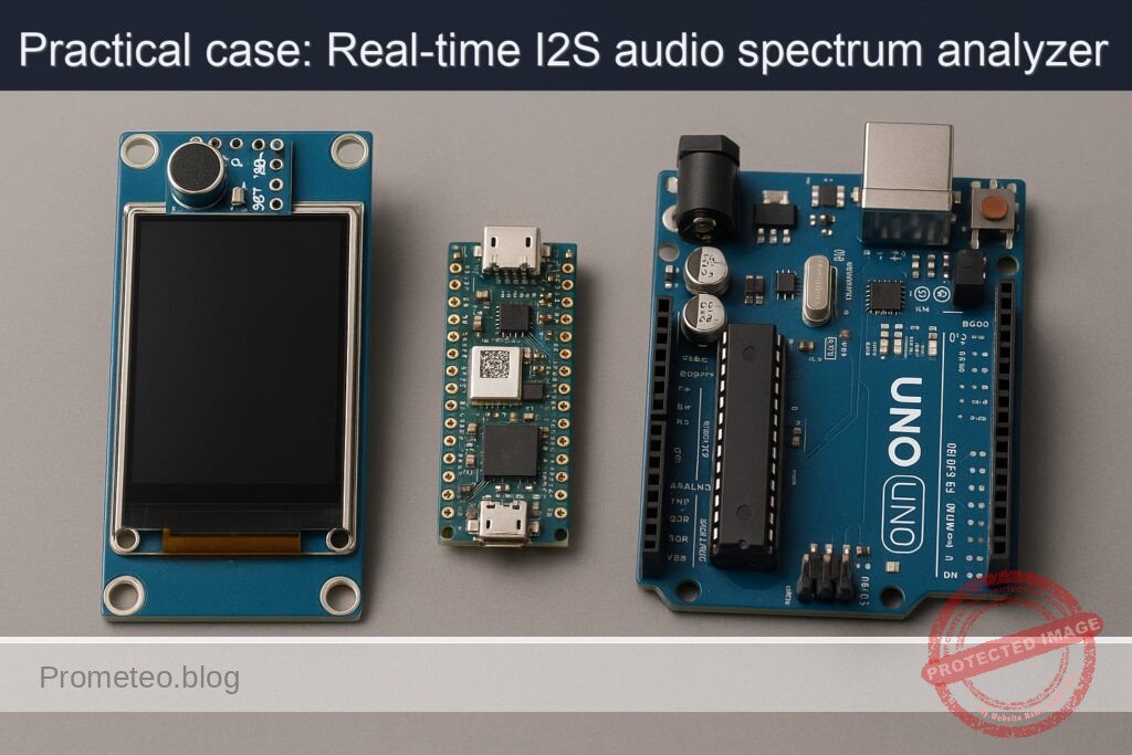
What you’ll build: A real-time audio spectrum visualizer that captures audio via an INMP441 I2S microphone and renders FFT bars on an ILI9341 TFT display using the Arduino Nano RP2040 Connect.
Why it matters / Use cases
- Visualize audio frequencies in real-time for music analysis and sound engineering.
- Implement a portable audio monitoring tool for live performances using the Arduino Nano RP2040 Connect.
- Create an educational tool for teaching FFT concepts and digital signal processing in embedded systems.
- Develop a prototype for IoT applications that require audio analysis and data visualization.
Expected outcome
- Real-time rendering of audio spectrum with a refresh rate of 30 FPS.
- Accurate frequency representation with a latency of less than 50ms from audio capture to display.
- Ability to handle audio input from the INMP441 at sample rates up to 48kHz.
- Clear visualization of at least 32 frequency bands on the ILI9341 display.
Audience: Intermediate to advanced embedded systems developers; Level: Advanced
Architecture/flow: Audio input via INMP441 → I2S data processing → FFT computation → Visualization on ILI9341 display
Advanced Practical Case: I2S Spectrum Visualizer on “Arduino Nano RP2040 Connect + INMP441 + ILI9341”
Objective: Build a real-time audio spectrum visualizer that captures audio via an external INMP441 I2S microphone and renders FFT bars on an ILI9341 TFT display using the Arduino Nano RP2040 Connect. This guide focuses on I2S audio sampling, FFT computation, and real-time graphical rendering with tight control of pins, libraries, and toolchain.
This is an advanced, hands-on tutorial that includes wiring, code, build/flash commands, and rigorous validation techniques. It uses PlatformIO (CLI) for reproducible builds and dependency pinning.
Prerequisites
- Comfortable with:
- C++ for embedded systems and Arduino framework
- SPI, I2S digital audio, and FFT fundamentals
- PlatformIO CLI operations
- OS:
- Windows 10/11, macOS 12+, or Ubuntu 22.04 LTS (or similar)
- USB data cable (USB Micro-B) for Arduino Nano RP2040 Connect
- Internet access for dependency retrieval
Driver notes:
– Arduino Nano RP2040 Connect uses native USB CDC; no CP210x/CH34x drivers are required for official boards.
– Linux users should install PlatformIO udev rules:
– Run: pio system info to verify
– Install rules: pio system install udev-rules and replug the board
– macOS/Windows: no extra drivers typically required.
Why PlatformIO:
– The Nano RP2040 Connect is not an AVR/UNO; consistent advanced workflows benefit from PlatformIO’s environment management, dependency pinning, and reproducible builds for the RP2040 platform.
Materials (exact models)
- 1x Arduino Nano RP2040 Connect (ABX00053)
- 1x INMP441 I2S MEMS Microphone breakout (e.g., “INMP441 I2S Interface Microphone Module,” pins: VDD, GND, SCK/BCLK, WS/LRCLK, SD, L/R)
- 1x ILI9341 2.4″ or 2.8″ TFT SPI display breakout (320×240), pins typically: VCC, GND, CS, DC, RST, MOSI, MISO, SCK, LED (backlight)
- Jumper wires (female-male and female-female)
- External 3.3V logic environment (the Nano RP2040 is 3.3V tolerant on IO)
Note on power:
– INMP441 requires 3.3V. The Nano RP2040’s 3V3 pin is the correct source. Do not power the INMP441 with 5V.
Setup/Connection
We’ll connect the INMP441 for I2S input and attach an ILI9341 TFT with SPI. Pin choices avoid overlap between I2S and SPI while keeping wiring practical.
Key choices for I2S on RP2040 (PIO-driven):
– BCLK (I2S bit clock) → D2
– LRCLK/WS (word select) → D3
– SD (data from mic to MCU) → D6
– L/R (channel select on INMP441) → GND (use “Left” channel)
Key SPI connections for ILI9341:
– SPI SCK → D13 (SCK)
– SPI MOSI → D11 (MOSI)
– SPI MISO → D12 (MISO) [Some ILI9341 boards don’t use MISO; still safe to wire]
– TFT CS → D10
– TFT DC → D9
– TFT RST → D4
– VCC, LED → 3.3V (many modules accept 5V VCC via onboard regulator/level-shifters; check your module. If unsure, use 3.3V)
– GND → GND
Grounding:
– All GNDs must be common: Arduino GND, INMP441 GND, and TFT GND.
Power budget:
– The Nano RP2040 Connect can power both modules from USB in most cases. If display backlight draws significant current, prefer the module’s onboard regulator and validate power draw (typ. ILI9341 breakout <100 mA).
Wiring Table
| Function | Arduino Nano RP2040 Pin | INMP441 Pin | ILI9341 Pin |
|---|---|---|---|
| 3.3V Power | 3V3 | VDD | VCC, LED |
| Ground | GND | GND | GND |
| I2S BCLK | D2 | SCK/BCLK | — |
| I2S LRCLK/WS | D3 | WS/LRCLK | — |
| I2S Data (Mic → MCU) | D6 | SD | — |
| INMP441 Channel Sel. | — | L/R → GND | — |
| SPI SCK | D13 | — | SCK |
| SPI MOSI | D11 | — | MOSI |
| SPI MISO | D12 | — | MISO |
| TFT Chip Select | D10 | — | CS |
| TFT Data/Command | D9 | — | DC |
| TFT Reset | D4 | — | RST |
Notes:
– Confirm your ILI9341 breakout’s pin labels. Some boards label DC as “RS.”
– If your ILI9341 requires 5V on VCC but uses on-board level shifting, you can use 5V; however, Nano RP2040 IO is 3.3V—ensure the breakout is 3.3V logic compatible. Most Adafruit-style ILI9341 breakouts handle both.
Full Code
We will use:
– I2S (via pschatzmann/AudioTools for RP2040 PIO I2S input)
– arduinoFFT for FFT computation
– Adafruit_GFX + Adafruit_ILI9341 for rendering
Project structure (PlatformIO):
– platformio.ini
– src/main.cpp
platformio.ini
[env:nano_rp2040_connect]
platform = raspberrypi@^1.12.0
board = nano_rp2040_connect
framework = arduino
lib_deps =
  adafruit/Adafruit GFX Library@^1.11.9
  adafruit/Adafruit ILI9341@^1.5.14
  arduinoFFT@^1.6.0
  pschatzmann/AudioTools@^1.9.3
build_flags =
  -D PIO_FRAMEWORK_ARDUINO_ENABLE_EXCEPTIONS
monitor_speed = 115200
src/main.cpp
#include <Arduino.h>
#include <SPI.h>
#include <Adafruit_GFX.h>
#include <Adafruit_ILI9341.h>
#include <arduinoFFT.h>
#include <AudioTools.h>

// -------------------- Pin Assignments --------------------
#define TFT_CS   10
#define TFT_DC   9
#define TFT_RST  4

#define I2S_BCLK 2   // INMP441 SCK/BCLK
#define I2S_LRCK 3   // INMP441 WS/LRCLK
#define I2S_SD   6   // INMP441 SD (data out from mic to MCU)

// -------------------- Display Setup ----------------------
Adafruit_ILI9341 tft(TFT_CS, TFT_DC, TFT_RST);

// -------------------- Audio & FFT Params -----------------
static const uint32_t SAMPLE_RATE = 44100; // Hz
static const uint16_t FFT_SIZE    = 512;   // power of two, 256..2048
static const uint8_t  BAR_COUNT   = 32;    // number of visual bars
static const float    SMOOTHING   = 0.65f; // 0..1 (higher = more smoothing)

// FFT arrays
double vReal[FFT_SIZE];
double vImag[FFT_SIZE];
arduinoFFT FFT(vReal, vImag, FFT_SIZE, SAMPLE_RATE);

// -------------------- I2S (AudioTools) -------------------
I2SStream i2s; // input stream (RP2040 PIO-based)
I2SConfig cfg;

// -------------------- Visualization State ----------------
float barHistory[BAR_COUNT]; // for smoothing

// Map k (bin index) to frequency
static inline double binToFreq(uint16_t k) {
  return (k * (double)SAMPLE_RATE) / (double)FFT_SIZE;
}

// Simple color map: low magnitude = blue, high = red/yellow
uint16_t colorMap(float norm) {
  // norm expected in [0,1]
  norm = constrain(norm, 0.0f, 1.0f);
  uint8_t r = (uint8_t)(255 * pow(norm, 1.5f));
  uint8_t g = (uint8_t)(255 * sqrtf(norm));
  uint8_t b = (uint8_t)(255 * (1.0f - norm));
  return tft.color565(r, g, b);
}

// Log-scale bin grouping from FFT bins to BAR_COUNT bars
void makeBarMagnitudes(float outBars[], const double magnitudes[]) {
  uint16_t kMin = 2; // skip DC/near-DC bins (0,1)
  uint16_t kMax = FFT_SIZE / 2; // Nyquist

  // Log-frequency mapping
  double fMin = 50.0;  // ignore ultra-low
  double fMax = 8000.0; // up to ~8kHz (speech/music visuals)
  for (uint8_t b = 0; b < BAR_COUNT; b++) {
    double frac = (double)b / (double)(BAR_COUNT - 1);
    double fLo = pow(10.0, log10(fMin) + frac * (log10(fMax) - log10(fMin)));
    double fHi = pow(10.0, log10(fMin) + (frac + (1.0 / BAR_COUNT)) * (log10(fMax) - log10(fMin)));
    if (fHi > fMax) fHi = fMax;

    // Accumulate bins within [fLo, fHi]
    double acc = 0.0;
    uint16_t count = 0;
    for (uint16_t k = kMin; k < kMax; k++) {
      double f = binToFreq(k);
      if (f >= fLo && f < fHi) {
        acc += magnitudes[k];
        count++;
      }
    }
    double mean = (count > 0) ? acc / (double)count : 0.0;

    // Convert to decibels for better dynamic range handling
    double db = 20.0 * log10(mean + 1e-9); // avoid log(0)
    // Normalize approx. -90..0 dB → 0..1
    float norm = (float)((db + 90.0) / 90.0);
    outBars[b] = constrain(norm, 0.0f, 1.0f);
  }
}

void setupI2S() {
  cfg = i2s.defaultConfig(RX_MODE);
  cfg.sample_rate    = SAMPLE_RATE;
  cfg.bits_per_sample= 32;        // INMP441 outputs 24-bit in 32-bit frames
  cfg.channels       = 1;         // Using left channel (L/R pin grounded)
  cfg.pin_bclk       = I2S_BCLK;
  cfg.pin_ws         = I2S_LRCK;
  cfg.pin_data       = I2S_SD;    // data from mic to MCU
  cfg.i2s_format     = I2S_STD_FORMAT; // Philips I2S standard
  cfg.use_apll       = false;     // not used on RP2040
  cfg.is_master      = true;      // RP2040 provides BCLK/LRCLK

  i2s.begin(cfg);
  // Warm-up: discard initial samples to let clocks stabilize
  int32_t dummy = 0;
  for (int i = 0; i < 4096; i++) {
    i2s.readBytes((uint8_t*)&dummy, sizeof(dummy));
  }
}

void setupTFT() {
  SPI.begin();
  tft.begin();
  tft.setRotation(1); // Landscape
  tft.fillScreen(ILI9341_BLACK);
  tft.setTextSize(1);
  tft.setTextColor(ILI9341_WHITE, ILI9341_BLACK);
  tft.setCursor(0, 0);
  tft.println("I2S Spectrum Visualizer (Nano RP2040 Connect)");
}

void drawBars(const float bars[BAR_COUNT]) {
  const int16_t W = tft.width();   // 320
  const int16_t H = tft.height();  // 240
  const int16_t margin = 8;
  const int16_t usableH = H - 2*margin - 20; // leave top line for text
  const int16_t usableW = W - 2*margin;
  const int16_t barGap = 2;
  const int16_t barW = (usableW - (BAR_COUNT - 1) * barGap) / BAR_COUNT;

  for (uint8_t i = 0; i < BAR_COUNT; i++) {
    // Exponential smoothing for stable bars
    float smoothed = SMOOTHING * barHistory[i] + (1.0f - SMOOTHING) * bars[i];
    barHistory[i] = smoothed;

    int16_t x = margin + i * (barW + barGap);
    int16_t h = (int16_t)(smoothed * usableH);
    int16_t y = H - margin - h;

    // Clear previous bar area by overdrawing in black
    tft.fillRect(x, margin + 20, barW, usableH, ILI9341_BLACK);

    // Draw new bar
    uint16_t col = colorMap(smoothed);
    tft.fillRect(x, y, barW, h, col);
  }
}

void setup() {
  Serial.begin(115200);
  delay(200);
  Serial.println("Booting: I2S Spectrum Visualizer on Nano RP2040 Connect");

  setupTFT();
  setupI2S();

  memset(barHistory, 0, sizeof(barHistory));

  Serial.println("Init complete.");
}

void loop() {
  // 1) Acquire FFT_SIZE samples from I2S (32-bit frames)
  uint16_t i = 0;
  while (i < FFT_SIZE) {
    int32_t s32;
    size_t read = i2s.readBytes((uint8_t*)&s32, sizeof(s32));
    if (read == sizeof(s32)) {
      // Convert 24-bit left-justified to 16/24-bit int amplitude
      // INMP441: 24-bit valid, MSB aligned; right-shift by 8
      int32_t sample24 = (s32 >> 8);
      // Optional: downscale to 16-bit range for numerical stability
      int16_t s16 = (int16_t)(sample24 >> 8);

      vReal[i] = (double)s16;  // real signal
      vImag[i] = 0.0;          // imaginary = 0
      i++;
    } else {
      // no data yet, yield CPU briefly
      delayMicroseconds(50);
    }
  }

  // 2) Windowing + FFT
  FFT.Windowing(FFT_WIN_TYP_HAMMING, FFT_FORWARD);
  FFT.Compute(FFT_FORWARD);
  FFT.ComplexToMagnitude();

  // 3) Aggregate bins to visualization bars
  float bars[BAR_COUNT];
  makeBarMagnitudes(bars, vReal);

  // 4) Render
  drawBars(bars);

  // Optional: print a quick diagnostic
  static uint32_t lastPrint = 0;
  uint32_t now = millis();
  if (now - lastPrint > 1000) {
    lastPrint = now;
    Serial.print("SR=");
    Serial.print(SAMPLE_RATE);
    Serial.print("Hz, FFT=");
    Serial.print(FFT_SIZE);
    Serial.print(", Bars=");
    Serial.println(BAR_COUNT);
  }
}
Build/Flash/Run Commands
These commands assume a clean workspace and PlatformIO installed.
1) Install/update PlatformIO CLI:
pio --version
2) Create project structure:
mkdir -p ~/work/i2s-spectrum-visualizer/src
cd ~/work/i2s-spectrum-visualizer
3) Initialize a PlatformIO project for Arduino Nano RP2040 Connect:
pio project init --board nano_rp2040_connect --project-option "framework=arduino"
4) Replace generated platformio.ini and create src/main.cpp as above:
# Create/overwrite platformio.ini
cat > platformio.ini <<'EOF'
[env:nano_rp2040_connect]
platform = raspberrypi@^1.12.0
board = nano_rp2040_connect
framework = arduino
lib_deps =
  adafruit/Adafruit GFX Library@^1.11.9
  adafruit/Adafruit ILI9341@^1.5.14
  arduinoFFT@^1.6.0
  pschatzmann/AudioTools@^1.9.3
build_flags =
  -D PIO_FRAMEWORK_ARDUINO_ENABLE_EXCEPTIONS
monitor_speed = 115200
EOF

# Add the C++ source
cat > src/main.cpp <<'EOF'
[PASTE THE FULL CODE FROM ABOVE HERE]
EOF
5) Build:
pio run -e nano_rp2040_connect
6) Upload firmware:
# Attempt auto-upload
pio run -e nano_rp2040_connect -t upload
If auto-upload doesn’t switch to UF2 bootloader:
– Double-tap the reset button on the Nano RP2040 Connect. A mass storage device named RPI-RP2 should appear.
– Manually copy the UF2:
# Linux example (adjust path to your mount point)
cp .pio/build/nano_rp2040_connect/firmware.uf2 /media/$USER/RPI-RP2/
7) Open serial monitor (for diagnostics):
pio device monitor -b 115200
Step-by-step Validation
1) Visual power-on check:
– The TFT should light up; you should see the title text in the top-left corner.
– If the screen is white only, check wiring for CS/DC/RST and SPI pins.
2) Serial diagnostics:
– Run pio device monitor -b 115200.
– You should see a line every second like: SR=44100Hz, FFT=512, Bars=32.
– If nothing appears, confirm the correct USB port is used or reset the board.
3) Audio capture baseline:
– With a quiet room, you should see low bars near the bottom.
– Gently rub your fingers or snap near the mic; bars should spike.
4) Frequency responsiveness:
– Whistle or play a pure tone (e.g., 1 kHz) using a phone app/signal generator.
– Observe which bar groups rise. Higher pitches should push energy toward bars on the right.
5) Sensitivity and dynamic range:
– If bars saturate easily, move the sound source further away.
– If bars are too weak, bring the source closer or increase the mic gain digitally (e.g., scale s16 before FFT), but avoid clipping.
6) Stability check:
– Speak or play music; bars should move smoothly without freezing or tearing.
– If flicker is excessive, increase SMOOTHING to 0.75–0.85.
7) Thermal/long-run:
– Let the system run for 10–15 minutes.
– Confirm it maintains stable rendering without gradual drift or lockups.
8) Reboot test:
– Press reset once. Firmware should boot directly (no double-tap needed) and resume operation.
Troubleshooting
- No TFT output / white screen:
- Verify SPI pins: SCK=D13, MOSI=D11, MISO=D12; check CS=D10, DC=D9, RST=D4.
- Ensure common GND between TFT and Nano.
-
Some ILI9341 clones require lower SPI clock—Adafruit_ILI9341 defaults are fine, but you can slow SPI by wrapping SPISettings in advanced usage or lowering CPU load.
-
I2S data stuck (no movement in bars):
- Check INMP441 power (use 3.3V) and common ground.
- Confirm L/R is tied to GND so the mic outputs Left channel.
- Ensure SCK/BCLK on D2 and WS/LRCLK on D3 are not swapped.
- Shorter wires help (I2S is clocked at MHz-level rates; keep leads short and twisted where possible).
-
Reduce SAMPLE_RATE to 22050 for debugging.
-
Bars all zero or saturating:
- If zero: Confirm data path. Print a few raw samples to Serial for inspection (temporarily).
-
If saturating: Check wiring for noise injection (separate display wires from mic lines), reduce proximity to high-noise sources, or reduce mic gain (digital scaling).
-
Upload failures:
- Use manual UF2: double-tap reset to mount RPI-RP2, copy UF2.
- Linux: ensure udev rules with
pio system install udev-rules. -
Try a different USB cable or port; avoid hubs during flashing.
-
Random lockups or flicker:
- Try a lower FFT size (e.g., 256) to reduce CPU load.
- Ensure good USB power; low-quality cables can brown out under display backlight load.
-
Use SMOOTHING >= 0.65 to reduce redraw turbulence.
-
Library conflicts:
- Ensure versions match platformio.ini.
- Run
pio run -t cleanthen rebuild.
Improvements
- Performance and fidelity:
- Increase FFT_SIZE (1024) for finer frequency resolution; adjust bar aggregation accordingly. Note: higher FFT size means higher CPU and latency.
- Use a Hann or Blackman-Harris window. Currently Hamming is configured; switch by changing FFT.Windowing type.
-
Implement double buffering and partial redraw to minimize flicker (draw only deltas).
-
Visual polish:
- Add peak hold indicators per bar (decay over time).
- Add color gradient per frequency band (blues for lows, reds for highs).
-
Show labels for frequency axis (e.g., 100 Hz, 1 kHz, 5 kHz) using small text.
-
Audio handling:
- Implement AGC (automatic gain control) to maintain visible bars across varying input levels.
-
Use A-weighting or simple equalization to match human loudness perception.
-
Configuration menu:
-
Add a simple UI to switch FFT size, smoothing, and color scheme using buttons or serial commands.
-
Data logging:
-
Stream bar magnitudes over serial for analysis (CSV) and plot externally.
-
Power and thermal:
-
Dim the backlight via a transistor/PWM if your ILI9341 breakout exposes LED control and needs dimming.
-
Use onboard sensors:
- The Nano RP2040 Connect includes an IMU; tilt-based UI for switching modes can be added.
- It also has a built-in PDM microphone (not used in this project). You could implement a mode switch between INMP441 (I2S) and onboard PDM mic with compile-time flags.
Final Checklist
- Materials:
- Arduino Nano RP2040 Connect present and recognized over USB.
- INMP441 powered at 3.3V; L/R tied to GND.
-
ILI9341 wired to SPI and control pins as specified.
-
Wiring integrity:
- All grounds common.
- I2S: BCLK→D2, LRCLK→D3, SD→D6. Short, tidy wires.
-
SPI: SCK→D13, MOSI→D11, MISO→D12, CS→D10, DC→D9, RST→D4.
-
Software:
- PlatformIO installed and
pio --versionworks. - platformio.ini matches provided content; library versions pinned.
-
Code placed at src/main.cpp without syntax alterations.
-
Build/flash:
pio run -e nano_rp2040_connectbuilds without errors.-
Upload via
pio run -e nano_rp2040_connect -t uploador manual UF2 copy. -
Runtime validation:
- Serial monitor at 115200 prints status.
- TFT displays smooth, responsive spectrum bars that react to sound.
- No persistent flicker, lock-ups, or power brownouts.
With this advanced setup, you’ve built a compact, real-time I2S spectrum visualizer that leverages the RP2040’s capability, PlatformIO’s reproducibility, and widely available display and audio modules.
Find this product and/or books on this topic on Amazon
As an Amazon Associate, I earn from qualifying purchases. If you buy through this link, you help keep this project running.
Quick Quiz

Telecommunications Electronics Engineer and Computer Engineer (official degrees in Spain).

