
Level: Medium. Design a control circuit to start industrial machinery from a main panel or a remote safety remote.
Objective and use case
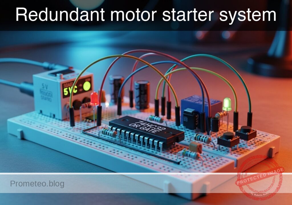
In this practical case, you will build a digital control circuit using an OR logic gate to operate a heavy-duty DC motor via a relay. The system allows the motor to be started from two distinct physical locations: the main control panel or a remote safety station.
- Operational Redundancy: Ensures machinery can be activated from a secondary location if the primary panel is inaccessible.
- Convenience: Allows operators to start a conveyor belt or fan from either end of a production line.
- Signal Isolation: Uses low-voltage logic (5V) to safely switch a high-power inductive load (motor) via a relay driver.
Expected outcome:
* Pressing Button A (Main) starts the motor immediately.
* Pressing Button B (Remote) starts the motor immediately.
* Logic Output High ($V_{OH}$) measures approximately 5V when either button is pressed.
* The relay produces an audible «click» and the DC motor spins when the logic condition is met.
Target audience: Electronics students and hobbyists familiar with basic logic gates and relay driving.
Materials
- V1: 5 V DC power supply, function: Main logic and relay power
- U1: 74HC32, function: Quad 2-input OR gate
- S1: Pushbutton (normally open), function: Main Start Panel
- S2: Pushbutton (normally open), function: Remote Start Command
- R1: 10 kΩ resistor, function: Pull-down for Input A
- R2: 10 kΩ resistor, function: Pull-down for Input B
- R3: 1 kΩ resistor, function: Transistor base current limiting
- Q1: 2N2222 NPN Transistor, function: Relay driver switch
- D1: 1N4007 Diode, function: Flyback protection for relay coil
- K1: 5 V Relay (SPDT), function: High-current switching
- M1: 5 V DC Motor, function: Industrial load simulation
Pin-out of the IC used
Chip: 74HC32 (Quad 2-Input OR Gate)
| Pin | Name | Logic function | Connection in this case |
|---|---|---|---|
| 1 | 1A | Input A | Connected to Node START_MAIN |
| 2 | 1B | Input B | Connected to Node START_REMOTE |
| 3 | 1Y | Output | Connected to Node LOGIC_OUT |
| 7 | GND | Ground | Connected to Node 0 |
| 14 | VCC | Power Supply | Connected to Node VCC |
Wiring guide
- V1 connects between node
VCCand node0(GND). - S1 connects between node
VCCand nodeSTART_MAIN. - R1 connects between node
START_MAINand node0. - S2 connects between node
VCCand nodeSTART_REMOTE. - R2 connects between node
START_REMOTEand node0. - U1 Pin 1 (1A) connects to node
START_MAIN. - U1 Pin 2 (1B) connects to node
START_REMOTE. - U1 Pin 3 (1Y) connects to node
LOGIC_OUT. - U1 Pin 14 (VCC) connects to node
VCC. - U1 Pin 7 (GND) connects to node
0. - R3 connects between node
LOGIC_OUTand nodeBASE_DRIVE. - Q1 Base connects to node
BASE_DRIVE. - Q1 Emitter connects to node
0. - Q1 Collector connects to node
RELAY_COIL_LO. - K1 Coil Positive connects between node
VCCand nodeRELAY_COIL_LO(Note: Coil connects VCC to Collector). - D1 connects between node
RELAY_COIL_LO(Anode) and nodeVCC(Cathode) (Reverse biased). - K1 Common contact connects to node
VCC. - K1 Normally Open (NO) contact connects to node
MOTOR_PWR. - M1 connects between node
MOTOR_PWRand node0.
Conceptual block diagram
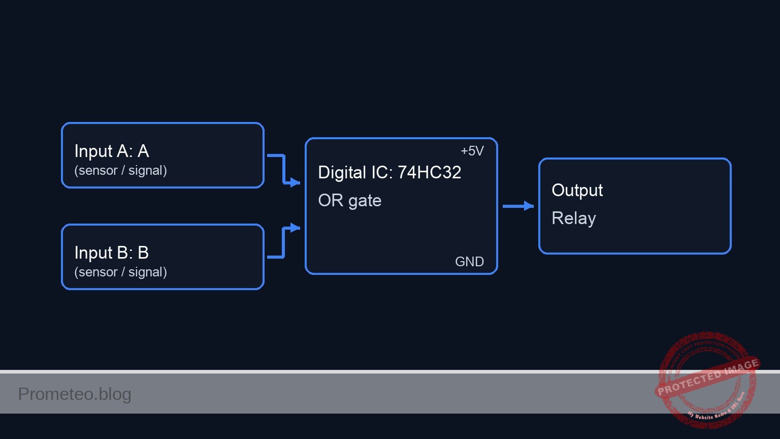
Schematic
Practical case: Redundant motor starter system

      [ INPUTS ]                     [ LOGIC ]                     [ DRIVER ]                   [ OUTPUT / LOAD ]

 [ S1: Main Start ] --+
                      |
 [ R1: Pull-down  ] --+--(Pin 1)-->+------------+
                                   |            |
                                   | U1: 74HC32 |             (Base Sig)
                                   | (OR Gate)  |--(Pin 3)--> [ R3: 1k ] --> [ Q1: NPN ] --(Sink)--> [ K1: Relay Coil ]
                                   |            |                               |                    (w/ D1 Diode)
 [ S2: Remote Cmd ] --+--(Pin 2)-->+------------+                            [ GND ]                       |
                      |                                                                                (Magnetic)
 [ R2: Pull-down  ] --+                                                                                    |
                                                                                                           v
                                                                                                   [ K1: NO Contact ]
                                                                                                           |
                                                                                                     (Switched 5V)
                                                                                                           |
                                                                                                           v
                                                                                                    [ M1: DC Motor ]
                                                                                                           |
                                                                                                        [ GND ]
Truth table
This system uses positive logic (active HIGH).
| Input A (Main) | Input B (Remote) | Output Y (Logic) | Relay State | Motor State |
|---|---|---|---|---|
| 0 (Open) | 0 (Open) | 0 (Low) | OFF | Stopped |
| 0 (Open) | 1 (Pressed) | 1 (High) | ON | Running |
| 1 (Pressed) | 0 (Open) | 1 (High) | ON | Running |
| 1 (Pressed) | 1 (Pressed) | 1 (High) | ON | Running |
Measurements and tests
- Input Validation ($V_{in_high}$): With neither button pressed, measure the voltage at
START_MAINandSTART_REMOTE. It should be 0V. Press S1 and verify the voltage rises to approx 5V. - Logic Output Verification ($V_{out_logic}$): Place a multimeter probe on Pin 3 of U1. Press S1 OR S2. The voltage should jump from near 0V to $\approx$ 5V.
- Actuator Test (Motor RPM): Observe the motor. It should spin when the logic output is High. If using a tachometer, verify the
Motor_RPMis consistent regardless of which button (S1 or S2) triggered the start.
SPICE netlist and simulation
Reference SPICE Netlist (ngspice) — excerptFull SPICE netlist (ngspice)
* Redundant motor starter system
* Created based on BOM and Wiring Guide

* --- Power Supply ---
* V1: 5 V DC power supply
V1 VCC 0 DC 5

* --- Input Section ---
* S1: Pushbutton (Main Start)
* Wiring: Connects VCC to START_MAIN.
* Implementation: Voltage Controlled Switch driven by a Stimulus Pulse (V_ACT1)
* Timing: Period 200us, covers logic states 00, 10, 11, 01 combined with S2
V_ACT1 ACT1 0 PULSE(0 5 10u 1u 1u 100u 200u)
S1 VCC START_MAIN ACT1 0 SW_PUSH

* R1: 10 kΩ resistor (Pull-down for Input A)
R1 START_MAIN 0 10k

* S2: Pushbutton (Remote Start)
* Wiring: Connects VCC to START_REMOTE.
* Implementation: Voltage Controlled Switch driven by a Stimulus Pulse (V_ACT2)
V_ACT2 ACT2 0 PULSE(0 5 10u 1u 1u 200u 400u)
S2 VCC START_REMOTE ACT2 0 SW_PUSH

* R2: 10 kΩ resistor (Pull-down for Input B)
R2 START_REMOTE 0 10k

* Model for Pushbuttons
.model SW_PUSH SW(Vt=2.5 Ron=0.1 Roff=10Meg)

* ... (truncated in public view) ...
Copy this content into a .cir file and run with ngspice.
* Redundant motor starter system
* Created based on BOM and Wiring Guide

* --- Power Supply ---
* V1: 5 V DC power supply
V1 VCC 0 DC 5

* --- Input Section ---
* S1: Pushbutton (Main Start)
* Wiring: Connects VCC to START_MAIN.
* Implementation: Voltage Controlled Switch driven by a Stimulus Pulse (V_ACT1)
* Timing: Period 200us, covers logic states 00, 10, 11, 01 combined with S2
V_ACT1 ACT1 0 PULSE(0 5 10u 1u 1u 100u 200u)
S1 VCC START_MAIN ACT1 0 SW_PUSH

* R1: 10 kΩ resistor (Pull-down for Input A)
R1 START_MAIN 0 10k

* S2: Pushbutton (Remote Start)
* Wiring: Connects VCC to START_REMOTE.
* Implementation: Voltage Controlled Switch driven by a Stimulus Pulse (V_ACT2)
V_ACT2 ACT2 0 PULSE(0 5 10u 1u 1u 200u 400u)
S2 VCC START_REMOTE ACT2 0 SW_PUSH

* R2: 10 kΩ resistor (Pull-down for Input B)
R2 START_REMOTE 0 10k

* Model for Pushbuttons
.model SW_PUSH SW(Vt=2.5 Ron=0.1 Roff=10Meg)

* --- Logic Section ---
* U1: 74HC32 Quad 2-input OR gate
* Pins: 1(A), 2(B), 3(Y), 7(GND), 14(VCC)
* Implemented as a subcircuit to expose all pins
XU1 START_MAIN START_REMOTE LOGIC_OUT VCC 0 74HC32_OR

.subckt 74HC32_OR A B Y VCC GND
* Behavioral OR logic using continuous tanh function for convergence
* Logic: If (A + B) > Threshold(2.5V), Output High
* Function scales 0-1 range to 0-5V
B1 Y GND V = 5 * (tanh(10 * (V(A) + V(B) - 2.5)) + 1) / 2
.ends

* --- Driver Section ---
* R3: 1 kΩ resistor (Base current limiting)
R3 LOGIC_OUT BASE_DRIVE 1k

* Q1: 2N2222 NPN Transistor (Relay driver)
* Connections: Base=BASE_DRIVE, Collector=RELAY_COIL_LO, Emitter=0
Q1 RELAY_COIL_LO BASE_DRIVE 0 2N2222
.model 2N2222 NPN(IS=1E-14 VAF=100 BF=200 IKF=0.3 XTB=1.5 BR=3 CJC=8p CJE=25p TR=46n TF=411p ITF=0.6 VTF=1.7 XTF=3 RB=10 RC=0.3 RE=0.2)

* --- Relay Section ---
* K1: 5 V Relay (SPDT)
* Coil Connection: VCC to RELAY_COIL_LO
* Modeled as Inductor + Series Resistance
L_K1 VCC K1_INT 10m
R_K1_COIL K1_INT RELAY_COIL_LO 100

* D1: 1N4007 Diode (Flyback protection)
* Connections: Anode=RELAY_COIL_LO, Cathode=VCC
D1 RELAY_COIL_LO VCC 1N4007
.model 1N4007 D(IS=7n RS=0.034 N=1.26 BV=1000 IBV=5u CJO=10p)

* Relay Contact Switch
* Wiring: Common(VCC) to NO(MOTOR_PWR)
* Controlled by voltage across the coil (VCC - RELAY_COIL_LO)
* Threshold set to 3V (Energized state)
S_K1 VCC MOTOR_PWR VCC RELAY_COIL_LO SW_RELAY
.model SW_RELAY SW(Vt=3.0 Ron=0.05 Roff=100Meg)

* --- Motor Load ---
* M1: 5 V DC Motor
* Wiring: MOTOR_PWR to 0
* Modeled as resistive load with slight inductance
R_M1 MOTOR_PWR M1_INT 20
L_M1 M1_INT 0 1m

* --- Simulation Directives ---
.op
.tran 1u 500u

* Print directive for transient analysis
.print tran V(START_MAIN) V(START_REMOTE) V(LOGIC_OUT) V(BASE_DRIVE) V(RELAY_COIL_LO) V(MOTOR_PWR)

.end
Simulation Results (Transient Analysis)

Show raw data table (1304 rows)
Index   time            v(start_main)   v(start_remote) v(logic_out)
0	0.000000e+00	4.995005e-03	4.995005e-03	0.000000e+00
1	1.000000e-08	4.995005e-03	4.995005e-03	0.000000e+00
2	2.000000e-08	4.995005e-03	4.995005e-03	0.000000e+00
3	4.000000e-08	4.995005e-03	4.995005e-03	0.000000e+00
4	8.000000e-08	4.995005e-03	4.995005e-03	0.000000e+00
5	1.600000e-07	4.995005e-03	4.995005e-03	0.000000e+00
6	3.200000e-07	4.995005e-03	4.995005e-03	0.000000e+00
7	6.400000e-07	4.995005e-03	4.995005e-03	0.000000e+00
8	1.280000e-06	4.995005e-03	4.995005e-03	0.000000e+00
9	2.280000e-06	4.995005e-03	4.995005e-03	0.000000e+00
10	3.280000e-06	4.995005e-03	4.995005e-03	0.000000e+00
11	4.280000e-06	4.995005e-03	4.995005e-03	0.000000e+00
12	5.280000e-06	4.995005e-03	4.995005e-03	0.000000e+00
13	6.280000e-06	4.995005e-03	4.995005e-03	0.000000e+00
14	7.280000e-06	4.995005e-03	4.995005e-03	0.000000e+00
15	8.280000e-06	4.995005e-03	4.995005e-03	0.000000e+00
16	9.280000e-06	4.995005e-03	4.995005e-03	0.000000e+00
17	1.000000e-05	4.995005e-03	4.995005e-03	0.000000e+00
18	1.010000e-05	4.995005e-03	4.995005e-03	0.000000e+00
19	1.026000e-05	4.995005e-03	4.995005e-03	0.000000e+00
20	1.030750e-05	4.995005e-03	4.995005e-03	0.000000e+00
21	1.039062e-05	4.995005e-03	4.995005e-03	0.000000e+00
22	1.041363e-05	4.995005e-03	4.995005e-03	0.000000e+00
23	1.045390e-05	4.995005e-03	4.995005e-03	0.000000e+00
... (1280 more rows) ...
Common mistakes and how to avoid them
- Floating Inputs: Forgetting R1 or R2 allows the input pins to «float,» causing the motor to switch on randomly due to electrostatic noise. Always use pull-down resistors with the 74HC series.
- Missing Flyback Diode: Omitting D1 allows high-voltage spikes from the relay coil to destroy Q1 or reset U1 when the motor turns off. Always install the diode in reverse parallel to the coil.
- Driving Relay Directly: Trying to power the relay coil directly from U1 Pin 3 will damage the IC, as logic gates cannot supply enough current. Always use a transistor (Q1) as a driver.
Troubleshooting
- Symptom: The motor runs continuously and never stops.
- Cause: One input is floating or shorted to VCC.
- Fix: Check R1/R2 connections and ensure buttons are not «Normally Closed» type.
- Symptom: Logic Output goes High, but Relay does not click.
- Cause: Transistor Q1 is not conducting or R3 is too high.
- Fix: Check Q1 pinout (C-B-E) and ensure the emitter goes to Ground.
- Symptom: The system resets or glitches when the relay turns off.
- Cause: Inductive kickback noise.
- Fix: Verify D1 is installed correctly (Cathode to VCC) and add a 100nF decoupling capacitor near U1 VCC.
Possible improvements and extensions
- Latch Circuit: Add a feedback loop so the motor stays on after the button is released (Start/Stop station).
- Safety Interlock: Add a 74HC08 (AND gate) in series with a «Safety Switch» so the motor only runs if the safety guard is closed AND a button is pressed.
More Practical Cases on Prometeo.blog
Find this product and/or books on this topic on Amazon
As an Amazon Associate, I earn from qualifying purchases. If you buy through this link, you help keep this project running.
Quick Quiz

Telecommunications Electronics Engineer and Computer Engineer (official degrees in Spain).

