
Level: Basic – Verify equivalent resistance formulas through measurement.
Objective and use case
In this practical case, you will build a passive circuit using two resistors to analyze how resistance values change when components are connected in series versus parallel. You will measure the total equivalent resistance (Req) using a multimeter in ohmmeter mode.
- Useful for:
- Designing voltage dividers for sensors or power supplies.
- Calculating total load resistance in power distribution networks.
- Adjusting specific resistance values when standard components are not available.
- Understanding current limiting paths in LED driver circuits.
- Expected outcome:
- Series Mode: The measured value should equal the sum of both resistors (Req ≈ 2 kΩ).
- Parallel Mode: The measured value should be half of the individual resistance (if R1=R2) or follow the parallel formula (Req ≈ 500 Ω).
- Verification: Measured values should fall within the tolerance range (e.g., ±5%) of the theoretical calculation.
- Target audience: Students and hobbyists learning fundamental laws of circuit analysis (Ohm’s Law).
Materials
- R1: 1 kΩ resistor, function: Test load A
- R2: 1 kΩ resistor, function: Test load B
- M1: Digital Multimeter, function: Resistance measurement (Ohmmeter)
- W1: Jumper wires, function: Circuit interconnection
Wiring guide
This guide uses specific node names. Ensure the circuit is not connected to a voltage source (battery) during resistance measurements.
Part A: Series Configuration
* R1: Connects between node Node_A and node Node_B.
* R2: Connects between node Node_B and node Node_C.
* M1 (Positive Probe): Connects to Node_A.
* M1 (Negative Probe): Connects to Node_C.
Part B: Parallel Configuration (Re-wiring required)
* R1: Connects between node Node_A and node Node_B.
* R2: Connects between node Node_A and node Node_B (physically parallel to R1).
* M1 (Positive Probe): Connects to Node_A.
* M1 (Negative Probe): Connects to Node_B.
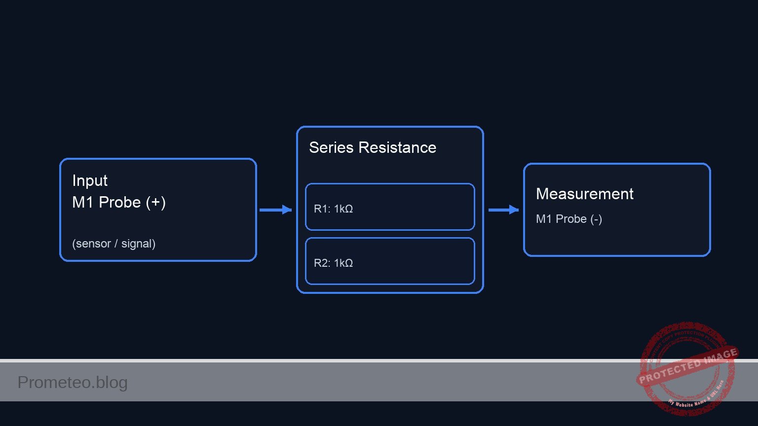
Conceptual block diagram
Schematic
PART A: SERIES CONFIGURATION (Current flows through R1 then R2)

      [ INPUT / SOURCE ]             [ CIRCUIT TOPOLOGY ]             [ RETURN / MEASURE ]

    [ M1 Probe (+) ] --(Node A)--> [ R1: 1kΩ ] --(Node B)--> [ R2: 1kΩ ] --(Node C)--> [ M1 Probe (-) ]


PART B: PARALLEL CONFIGURATION (Current splits between R1 and R2)

      [ INPUT / SOURCE ]             [ CIRCUIT TOPOLOGY ]             [ RETURN / MEASURE ]

                                         +--> [ R1: 1kΩ ] --+
    [ M1 Probe (+) ] --(Node A)--> [ SPLIT ]                [ JOIN ] --(Node B)--> [ M1 Probe (-) ]
                                         +--> [ R2: 1kΩ ] --+
Measurements and tests
Perform these steps with the multimeter set to the Ohms (Ω) setting (start with the 20k range if manual).
- Component verification:
- Measure R1 and R2 individually before connecting them. Confirm they are approximately 1 kΩ each.
- Series measurement:
- Construct the circuit described in Part A of the Wiring Guide.
- Connect the probes to
Node_AandNode_C. - Validation: The display should read approximately 2.0 kΩ ($R1 + R2$).
- Parallel measurement:
- Modify the circuit to match Part B of the Wiring Guide (connect both resistor ends to the same pair of rows).
- Connect the probes across the parallel pair.
- Validation: The display should read approximately 0.5 kΩ (500 Ω).
- Comparison:
- Observe that the series combination increases total resistance, while the parallel combination decreases total resistance.
SPICE netlist and simulation
Reference SPICE Netlist (ngspice) — excerptFull SPICE netlist (ngspice)
* Practical case: Series and parallel resistors
*
* This netlist implements both Part A (Series) and Part B (Parallel)
* configurations as separate sub-circuits to allow simultaneous simulation.
*
* BOM:
* R1, R2: 1 kΩ resistors
* M1: Digital Multimeter (Simulated as 1mA Current Source for Resistance Measurement)
* W1: Jumper wires (Implicit in netlist connectivity)

* ==============================================================================
* GLOBAL SETTINGS
* ==============================================================================
* Global Ground is Node 0.
* Unused System Supply (Required by prompt constraints)
VCC_Supply VCC 0 DC 5

* ==============================================================================
* PART A: SERIES CONFIGURATION
* ==============================================================================
* ... (truncated in public view) ...
Copy this content into a .cir file and run with ngspice.
* Practical case: Series and parallel resistors
*
* This netlist implements both Part A (Series) and Part B (Parallel)
* configurations as separate sub-circuits to allow simultaneous simulation.
*
* BOM:
* R1, R2: 1 kΩ resistors
* M1: Digital Multimeter (Simulated as 1mA Current Source for Resistance Measurement)
* W1: Jumper wires (Implicit in netlist connectivity)

* ==============================================================================
* GLOBAL SETTINGS
* ==============================================================================
* Global Ground is Node 0.
* Unused System Supply (Required by prompt constraints)
VCC_Supply VCC 0 DC 5

* ==============================================================================
* PART A: SERIES CONFIGURATION
* ==============================================================================
* Wiring Guide Mapping:
* Node_A -> Node_A_Ser
* Node_B -> Node_B_Ser
* Node_C -> Node_C_Ser
*
* Connections:
* R1 connects between Node_A and Node_B
* R2 connects between Node_B and Node_C
* M1 (Ohmmeter) connects to Node_A (+) and Node_C (-)
*
* Simulation Logic:
* Ohmmeter is modeled as a 1mA Current Source (I_M1_Ser) injecting into the
* positive probe node, with the negative probe node grounded.
* V(Node_A_Ser) = Resistance * 1mA => 1V = 1kΩ.

I_M1_Ser     0            Node_A_Ser   DC 1m
R1_Ser       Node_A_Ser   Node_B_Ser   1k
R2_Ser       Node_B_Ser   Node_C_Ser   1k
V_M1_Ret_Ser Node_C_Ser   0            DC 0   ; Ground return for M1 (-)

* ==============================================================================
* PART B: PARALLEL CONFIGURATION
* ==============================================================================
* Wiring Guide Mapping:
* Node_A -> Node_A_Par
* Node_B -> Node_B_Par
*
* Connections:
* R1 connects between Node_A and Node_B
* R2 connects between Node_A and Node_B (Physically parallel)
* M1 (Ohmmeter) connects to Node_A (+) and Node_B (-)

I_M1_Par     0            Node_A_Par   DC 1m
R1_Par       Node_A_Par   Node_B_Par   1k
R2_Par       Node_A_Par   Node_B_Par   1k
V_M1_Ret_Par Node_B_Par   0            DC 0   ; Ground return for M1 (-)

* ==============================================================================
* ANALYSIS DIRECTIVES
* ==============================================================================
* Transient analysis to satisfy prompt requirements for logging
.tran 100u 5ms

* Print voltages representing resistance values
* V(Node_A_Ser) should be ~2.0V (2kΩ)
* V(Node_A_Par) should be ~0.5V (500Ω)
.print tran V(Node_A_Ser) V(Node_B_Ser) V(Node_A_Par)

* DC Operating Point for quick verification
.op

.end
Simulation Results (Transient Analysis)

Show raw data table (59 rows)
Index   time            v(node_a_ser)   v(node_b_ser)   v(node_a_par)
0	0.000000e+00	2.000000e+00	1.000000e+00	5.000000e-01
1	5.000000e-07	2.000000e+00	1.000000e+00	5.000000e-01
2	1.000000e-06	2.000000e+00	1.000000e+00	5.000000e-01
3	2.000000e-06	2.000000e+00	1.000000e+00	5.000000e-01
4	4.000000e-06	2.000000e+00	1.000000e+00	5.000000e-01
5	8.000000e-06	2.000000e+00	1.000000e+00	5.000000e-01
6	1.600000e-05	2.000000e+00	1.000000e+00	5.000000e-01
7	3.200000e-05	2.000000e+00	1.000000e+00	5.000000e-01
8	6.400000e-05	2.000000e+00	1.000000e+00	5.000000e-01
9	1.280000e-04	2.000000e+00	1.000000e+00	5.000000e-01
10	2.280000e-04	2.000000e+00	1.000000e+00	5.000000e-01
11	3.280000e-04	2.000000e+00	1.000000e+00	5.000000e-01
12	4.280000e-04	2.000000e+00	1.000000e+00	5.000000e-01
13	5.280000e-04	2.000000e+00	1.000000e+00	5.000000e-01
14	6.280000e-04	2.000000e+00	1.000000e+00	5.000000e-01
15	7.280000e-04	2.000000e+00	1.000000e+00	5.000000e-01
16	8.280000e-04	2.000000e+00	1.000000e+00	5.000000e-01
17	9.280000e-04	2.000000e+00	1.000000e+00	5.000000e-01
18	1.028000e-03	2.000000e+00	1.000000e+00	5.000000e-01
19	1.128000e-03	2.000000e+00	1.000000e+00	5.000000e-01
20	1.228000e-03	2.000000e+00	1.000000e+00	5.000000e-01
21	1.328000e-03	2.000000e+00	1.000000e+00	5.000000e-01
22	1.428000e-03	2.000000e+00	1.000000e+00	5.000000e-01
23	1.528000e-03	2.000000e+00	1.000000e+00	5.000000e-01
... (35 more rows) ...
Common mistakes and how to avoid them
- Measuring resistance with power on: Never measure resistance in a live circuit. This will give false readings and may blow the fuse in your multimeter. Solution: Disconnect all batteries or power supplies before using the ohmmeter.
- Touching the metal probes: If you hold the metal tips of the probes with both hands while measuring, your body’s resistance (parallel to the circuit) will affect the reading, especially with high-value resistors. Solution: Use alligator clips or press the probes against the breadboard without touching the metal tips.
- Assuming perfect values: A 1 kΩ resistor with 5% tolerance can physically measure between 950 Ω and 1050 Ω. Solution: Always measure the individual components first to know their actual values before calculating the expected total.
Troubleshooting
- Symptom: Multimeter reads «1» or «OL» (Over Limit).
- Cause: The resistance is higher than the selected range on the multimeter.
- Fix: Switch the dial to a higher range (e.g., from 200 Ω to 2 kΩ or 20 kΩ).
- Symptom: Reading is 0 Ω.
- Cause: Short circuit; the probes might be touching each other or a wire is bypassing the resistors.
- Fix: Check the breadboard rows to ensure the resistors are not shorted out by a misplaced jumper.
- Symptom: Reading fluctuates or is unstable.
- Cause: Poor contact between the resistor leads and the breadboard clips.
- Fix: Remove the resistor, straighten the legs, and re-insert it firmly into different holes on the same node.
Possible improvements and extensions
- Mixed topology: Add a third resistor (R3 = 1 kΩ) in series with the parallel pair of R1 and R2 to create a Series-Parallel combination. Calculate and verify the new total (1.5 kΩ).
- Variable resistance: Replace R2 with a 10 kΩ potentiometer. Measure how the total resistance changes in both series and parallel configurations as you turn the knob.
More Practical Cases on Prometeo.blog
Find this product and/or books on this topic on Amazon
As an Amazon Associate, I earn from qualifying purchases. If you buy through this link, you help keep this project running.
Quick Quiz

Telecommunications Electronics Engineer and Computer Engineer (official degrees in Spain).

